EP1175983A2 - Procédé et appareil pour la fabrication d'articles en béton en forme de cuve, en particulier d'éléments de trou d'homme - Google Patents
Procédé et appareil pour la fabrication d'articles en béton en forme de cuve, en particulier d'éléments de trou d'homme Download PDFInfo
- Publication number
- EP1175983A2 EP1175983A2 EP01117528A EP01117528A EP1175983A2 EP 1175983 A2 EP1175983 A2 EP 1175983A2 EP 01117528 A EP01117528 A EP 01117528A EP 01117528 A EP01117528 A EP 01117528A EP 1175983 A2 EP1175983 A2 EP 1175983A2
- Authority
- EP
- European Patent Office
- Prior art keywords
- mold
- jacket
- formwork
- core
- formwork element
- Prior art date
- Legal status (The legal status is an assumption and is not a legal conclusion. Google has not performed a legal analysis and makes no representation as to the accuracy of the status listed.)
- Withdrawn
Links
Images






Classifications
-
- B—PERFORMING OPERATIONS; TRANSPORTING
- B28—WORKING CEMENT, CLAY, OR STONE
- B28B—SHAPING CLAY OR OTHER CERAMIC COMPOSITIONS; SHAPING SLAG; SHAPING MIXTURES CONTAINING CEMENTITIOUS MATERIAL, e.g. PLASTER
- B28B7/00—Moulds; Cores; Mandrels
- B28B7/0002—Auxiliary parts or elements of the mould
- B28B7/0014—Fastening means for mould parts, e.g. for attaching mould walls on mould tables; Mould clamps
-
- B—PERFORMING OPERATIONS; TRANSPORTING
- B28—WORKING CEMENT, CLAY, OR STONE
- B28B—SHAPING CLAY OR OTHER CERAMIC COMPOSITIONS; SHAPING SLAG; SHAPING MIXTURES CONTAINING CEMENTITIOUS MATERIAL, e.g. PLASTER
- B28B7/00—Moulds; Cores; Mandrels
- B28B7/02—Moulds with adjustable parts specially for modifying at will the dimensions or form of the moulded article
- B28B7/04—Moulds with adjustable parts specially for modifying at will the dimensions or form of the moulded article one or more of the parts being pivotally mounted
-
- B—PERFORMING OPERATIONS; TRANSPORTING
- B28—WORKING CEMENT, CLAY, OR STONE
- B28B—SHAPING CLAY OR OTHER CERAMIC COMPOSITIONS; SHAPING SLAG; SHAPING MIXTURES CONTAINING CEMENTITIOUS MATERIAL, e.g. PLASTER
- B28B7/00—Moulds; Cores; Mandrels
- B28B7/16—Moulds for making shaped articles with cavities or holes open to the surface, e.g. with blind holes
- B28B7/168—Moulds for making shaped articles with cavities or holes open to the surface, e.g. with blind holes for holders or similar hollow articles, e.g. vaults, sewer pits
Definitions
- the invention relates to a method for producing a cup-shaped Concrete molding, for example a piece of manhole bottom.
- manhole base pieces which are manufactured as prefabricated parts in concrete factories
- formwork elements for example recess cores
- the inlets and outlets or the associated recess cores not only in their circumferential position on the bottom of the manhole, but also in their height position with respect to the vertical axis of the manhole base and finally also in their number of manhole bottom pieces to vary the bottom of the manhole, in practice almost every one Manhole base piece an individual concrete element.
- Manhole base pieces in small and low versions are often used in the Turning process manufactured.
- the molding device is constructed so that the shape changes during the filling and compacting of the concrete Upside down position, i.e. in a position opposite the installation in the shaft about a horizontal axis rotated by 180 °. After compacting of the concrete by vibrating and pressing then the shape together with the just manufactured manhole base piece turned into the installation position, and that Then remove the bottom of the manhole from the mold.
- Such Manufacturing method is described for example in DE 43 42 518 A1.
- Manhole base pieces in larger and higher versions are usually manufactured according to the overhead process. With this The mold is not only filled with concrete in the overhead position. Rather, the freshly made manhole bottom piece is also upside down unlocked and remains until after the Concrete in this overhead position.
- the overhead method has the advantage of one more precise formation of the socket joint for the subsequent manhole ring. With regard to the overhead method, reference is made to EP 0 454 098 A1 directed.
- Both in the turning process and in the overhead process are the recess cores after removing the formwork from a previous one manufactured manhole bottom piece, i.e. one in the previous cycle manufactured piece of manhole bottom, before filling the concrete for the next manhole bottom piece usually by an operator inserted into the mold cavity by hand.
- this operator can the required recess cores already from one for this provided modular system and near the Have placed the molding device.
- the adjustment and attachment of the Cut-out cores in the desired circumferential and height position in the However, mold cavities take considerable time. This increases the time required to manufacture a manhole bottom piece and lowers thus the number that can be produced per day with this molding device Shaft bottom pieces.
- insert elements for example reinforcement rings or crampons, i.e. So elements that, in contrast to the recess cores in the finished Concrete molding remain and always in the same place in the Mold cavity must be introduced by means of an insertion aid in the Insert mold cavity (see DE 35 07 270 C2).
- the object of the present invention is a method for producing a pot-shaped concrete part, for example one Manhole bottom piece, to indicate which allows the manufacturing of a manhole base piece to reduce the time required and thus the time of number of manhole base pieces of the molding device per unit of time to increase.
- a method for Manufacture of a pot-shaped concrete part for example a manhole base piece, in a mold with a mold axis, the mold a Mold core, a mold jacket and, if desired, a lower sleeve which enclose a mold cavity between them, wherein at least one formwork element, for example at least one Cut-out core during the ongoing production of a previous one Concrete molding on a set-up device on one - related to one Form axis essentially parallel setup axis - on one predetermined circumferential and / or axial position is arranged, and the set-up device after removing the formwork from the previous one Concrete molded part with the form jacket and / or the form core in cover is brought, and the at least one formwork element in this Cover position by means of at least one transfer device to the Mold jacket or / and the mold core is passed.
- at least one formwork element for example at least one Cut-out core during the ongoing production of a previous one Concrete molding on a set-up device on one
- the operator can use the at least one formwork element, i.e. for example the at least one recess core, assemble from a modular system and on the for each Formwork element predetermined circumferential and / or axial position on the Attach the set-up device while at the same time the previous molding is concreted, i.e. the concrete is poured into the prepared mold cavity and compacted there by vibrating and pressing and then that the molded concrete part thus removed and removed for hardening becomes.
- the at least one formwork element i.e. for example the at least one recess core
- the at least one circuit element can be attached to the set-up device in attached or held in various ways:
- At least a formwork element or a part connected to it on the Set-up device can be held by means of a plug connection. It can the connector the formwork element or with this connected part on the set-up device with respect to the set-up axis in a radial Secure in the direction and in the circumferential direction.
- the at least one formwork element or the part connected to this on the set-up device a holding device is held.
- This alternative is particularly advantageous if the formwork elements on the Bracket unit "hung", i.e. the bracket unit in the Setup operation is located above the formwork elements arranged on it.
- the mounting device can, for example, at least one clamping pin comprise, which is preferably hydraulically or pneumatically actuated.
- the mounting device can be a locking device is formed, this locking device preferably comprises at least one locking element, which is biased into a locking position, is spring-loaded, for example.
- the locking element can then by the interaction of control surfaces of the locking element on the one hand and the formwork element or the part connected to it on the other hand or / and can be disengaged from this locking position by means of a power device, the power device, for example, a ring provided with wedge surfaces rotated about an axis substantially parallel to the set-up axis, which acts on a plurality of locking elements.
- the mounting unit can preferably be one over the entire Include circumference of the concrete molding extending retaining ring.
- On this retaining ring can the formwork elements in the circumferential direction can be arranged continuously displaceable.
- this mounting ring it is also an alternative possible on this mounting ring in a predetermined circumferential grid Attachment or mounting positions for the formwork elements or the provided with these connected parts.
- the height or axial position of the formwork element on the set-up device can be easily adjusted as desired, that the at least one formwork element on a mounting bar is adjustable in height can be attached, for example screwed down.
- this mounting bar which can be made of sheet steel, for example, the formwork element can then be attached to the mounting unit are or are gripped by the mounting device.
- the set-up device can be a Include a plurality of bracket arms, their circumferential and / or axial position is essentially adjustable.
- the set-up device can comprise a carriage that on an underground of the manufacturing site, for example the floor of a Production hall that is movable.
- This variant is suitable especially for retrofitting existing molds a molding device according to the invention.
- the set-up device comprises a carriage, the longitudinal a rail that can be moved from a base of the production site, for example the floor of a production hall, has a distance, for example more than 2.00 m, preferably more than 2.50 m, is.
- the set-up device can prevent vertical movement comprise a support body for supporting the at least one formwork element.
- This support body can when retracting the set-up device into the molded jacket, be it due to movement of the molded jacket or be it due to a movement of the set-up device, quasi the presence simulate a mandrel.
- the support body when moving the set-up device onto the mandrel, that too Simulate the presence of the shaped jacket.
- the support body can at the same time the function of the mounting device discussed above take over if on it in the circumferential direction and / or in the height direction a mounting grid for formwork elements is provided.
- the set-up device in the mold shell freed from the mold core are retracted, be it due to a movement of the molded jacket or because of a actual retraction of the set-up device.
- the set-up device freed from the molded jacket Open mold core it is also possible to get the set-up device freed from the molded jacket Open mold core.
- the transfer device comprises a mounting device which, for example, in Form of a clamping device arranged on the mold jacket and / or on the mold core can be executed.
- a clamping device arranged on the mold jacket and / or on the mold core can be executed.
- the clamping device can, for example, be one with a pressure fluid include loadable clamp hose.
- the pressure fluid chamber this
- the clamping hose can extend over the entire circumference of the Mold shell or mold core extend so that all to be transferred Formwork elements are captured simultaneously by the clamping device can.
- the clamping device can also comprise at least one clamping pin.
- the clamping hose or the clamping pin can be in a side wall a circumferential groove of the mold jacket or the mold core can be arranged, in which the at least one formwork element or with this connected part, such as the mounting bar, are inserted can.
- This circumferential groove does not necessarily need to be over to extend the entire circumference of the mold shell or mold core. Rather, it is also possible, particularly in the case of the raster solution, to have one A plurality of vertical grooves arranged distributed in the circumferential direction to provide, the circumferential distribution preferably the desired Corresponds to the circumferential grid.
- the holding device can also have at least one on the molded jacket or form core comprising clamping hooks displaceable in the radial direction, which encompasses the associated formwork element or its mounting strip and by means of a movement in the radial direction against the associated one Side wall of the mold core or mold jacket pulls.
- the clamp hook can encompass the formwork element or its mounting bar on the outside.
- the hook element it is also possible for the hook element to have an elongated one Penetration of the shell element or its mounting strip, wherein a longitudinal end of this opening is expanded, so that the hook element can pass through them easily, and that each other longitudinal end is narrowed, so that the hook element after a relative movement of the hook element and through hole engage behind an edge of this narrowed longitudinal end of the through hole and the formwork element or the assembly bar when pulling back in the radial direction against the mold core or the mold jacket can pull.
- the set-up device can be rotatable. This does not always have to be the case the entire set-up device can be rotated. Especially with the Formation of the set-up device with a plurality of mounting arms Rather, it is sufficient if these arms can be pivoted. This Rotatability or pivotability can be used for this purpose, for example that the operator's setup is always in position returns to where the next formwork element is to be arranged. The operator so does not need to walk around the setup, what helps to reduce set-up times.
- a display device can also be provided, which indicates the position at which the next formwork element is to be arranged is.
- a control device can be provided which Manufacturing process including the delivery of at least one Formwork element controls by means of the set-up device, preferably controls fully automatically.
- the Invention also a device for manufacturing a pot-shaped concrete part, especially a piece of manhole bottom.
- the Training of this device according to the invention its training opportunities, as well as the discussion of the advantages that can be achieved with it referred to the above discussion of the method according to the invention.
- Fig. 1 is a plant according to the invention for the production of molded concrete parts generally designated 10. It serves in particular for Production of pot-shaped concrete parts using the overhead process.
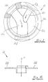
- FIG. 3 is an example of such a pot-shaped concrete molded part Shaft bottom piece 12 shown in plan view.
- the manhole base piece 12 comprises a pot bottom 12a and one up from it, i.e. from the Out of the drawing plane, protruding pot wall 12b.
- a main channel 12c runs in the pot bottom 12a, into which a side channel 12d opens as an inlet.
- the main channel 12c stands via an inflow opening 12e with an inlet line, not shown, and via a drain opening 12f with a likewise not shown Drain pipe in connection.
- the side channel 12d stands in an analogous manner via an inflow opening 12g with another, also not shown Inlet line in connection.
- the flow directions in the main channel 12c or secondary channel 12d are indicated in FIG. 3 by arrows.
- the main channel 12c extends from its Inlet 12e to its outlet 12f, so that this can also be done via the secondary channel 12d to be able to absorb incoming liquid volumes. Therefore, all point three openings 12e, 12f and 12g have a different diameter.
- the main trough 12c takes place in the manhole bottom piece 12 a curved course, depending on the local conditions and requirements of the sewage pipe is predetermined, the part of which Manhole base piece 12 forms. The circumferential position also depends accordingly and the height position of the inlet opening 12g of the secondary channel 12d of the respective local conditions and requirements.
- inlet or outlet openings 12e, 12f and 12g must namely in the from the jacket 14, from the lower sleeve 15th (see detailed view) and the mold cavity 18 formed by the mold core 16 (see Fig. 1) recess cores 20 with one of the desired location of the corresponding opening and circumferential position become. So far, this has been done after demoulding an im preceding work cycle of manhole base 12, i.e. after the mold jacket 14 to form the mold cavity 18 again the mandrel 16 lowered into the position shown in dashed lines in FIG.
- the set-up device 22 is initially shown in horizontal direction in vertical alignment with the shaped jacket 14 or Move mold core 16.
- the embodiment according to FIG. 1 happens this by means of a transport carriage 22a, the wheels or rollers 22b of which have such a distance from each other that they are next to the Mold cavity 18 can move past this.
- the molded jacket is then used 14 lowered by means of the lifting device 10d until the set-up device 22 is completely accommodated in its interior 14a.
- a takeover device 24 is actuated, which the recess cores 20 secures inside the shaped jacket 14.
- the Molded jacket 14 again lifted from the set-up device 22, the Notch cores 20 from a mounting ring 22c of the set-up device 22 be solved.
- the shaped jacket 14 to form the Mold cavity 18 lowered onto the mandrel 16.
- the insertion of the set-up device 22 into the Interior 14a of the shell 14 also by a vertical movement of the Setup 22 are accomplished.
- the carriage 22a for example, be equipped with a lifting device.
- the set-up device 22 can be considered a vertical movement on the mandrel 16, be it before or after lowering the shaped jacket 14 in dashed lines in FIG. 1 position shown.
- the Setup 22 will be discussed below on the occasion of the Turning method are discussed in more detail with reference to FIG. 2.
- the recess cores 20 on the mounting ring 22c are arranged by means of mounting strips 32 on which the actual Notch cores 20 attached in a desired height position are. In the further description, however, is not between the recess cores 20 or the mounting strips bearing these become.
- a main difference of the manufacturing system 110 shown in FIG. 2 of manhole base pieces in the turning process exists compared to the 1 in that the molded jacket 114 and the mandrel 116 are usually continuously connected and therefore the recess cores 120 necessarily into the mold cavity 118 must be lowered.
- the set-up device 122 carries this through a "hanging" training bill, compared to the "standing" design of the set-up device 22 according to FIG. 1. "hanging” in that the recess cores 120 on the retainer ring 122c of the Setup 122 are suspended, i.e. from this down protrude.
- the mounting ring 122c on the carriage 122a is the Set-up device 122 suspended, which runs in horizontal rails 122d.
- the rails 122d are preferably spaced apart from one another from underground U, i.e. a distance of more than 2.00 m, preferably of more than 2.50 m.
- the set-up device 122 After the set-up device 122 in a horizontal movement H in vertical registration with the mold cavity 118, it will lowered into the mold cavity 18 by means of a vertical movement V, and the recess cores 120 from the takeover device 124 in the mold cavity 118 taken over. To enable this vertical movement V is the mounting ring 122c with the carriage 122a over one Telescopic arm 122e connected.
- FIG. 2 also shows a bearing 126 for prepared recess cores 120 and a work table 128, on which the recess cores 120 can be prepared for attachment to the set-up device 122. If an operator has a certain recess core on the Bracket ring 122c in the desired circumferential and height position arranged, it can do so by making an appropriate entry on a Acknowledge control unit 130. The control unit 130 can then Specifications for the one to be placed next on the set-up device 122 Display recess core 120 and the retaining ring 122c twist about a vertical axis so that the operator the correct circumferential position for this next recess core 120 returns.
- the control unit 130 acknowledges before filling and compressing the Concrete in the mold cavity 118 and the demoulding of the previous one Manhole bottom piece is finished; so the work cycle of the manufacturing plant 110 after stripping the manhole base without interruption continue running right away. Otherwise the manufacturing process interrupted and only as a result of the acknowledgment for the last required Cutout core started again.
- a preparation table 123 can be provided for work.
- the worktop 123a of this preparation table 123 can be operated by means of a Power device 123b, for example a pneumatic and / or hydraulic actuatable cylinder-piston unit, between one essentially horizontal preparatory position and a substantially vertical mounting position be pivoted.
- a Power device 123b for example a pneumatic and / or hydraulic actuatable cylinder-piston unit
- the set-up device In the embodiment shown in FIG. 2a, 122 ' is similar to that Embodiment according to FIG. 2 moving device movable along a crane rail with a mounting ring 122c 'for "standing" arrangement of the Recess cores 122 similar to the embodiment shown in FIG. 1.
- the production system 110 also corresponds to the Plant parts 10a, 10b and 10c according to FIG. 1 via a concrete loading device, has a pressing device and a vibrating device, it also goes without saying that the production system 10 according to FIG. 1 with a control unit corresponding to control unit 130 according to FIG. 2 can be equipped and that the mounting ring 22c on the Carriage 22a under the control of this control unit by one vertical Axis can be arranged rotatably.
- FIG. 4a shows a first embodiment variant of a mounting device 40 shown, such as on the mounting ring 22c of the set-up device 22 according to FIG. 1 can be used.
- the bracket device 40 designed as a plug connection.
- This is in the lower end of the mounting bar 32 carrying the recess core 20 a
- Longitudinal groove 32a is introduced into which a plug finger 42a of a plug head 42 can intervene.
- the webs 32b laterally delimiting the groove 32a, the interact with side surfaces of the insertion finger 42a is a shift the mounting bar 32 prevented in the circumferential direction.
- a movement the mounting bar 32 is radially outwards by the mounting finger 42a prevented.
- the plug head 42 has a support element 42b which also makes a movement radially inwards impossible.
- This backup the mounting bar 32 both in the radial direction and in the circumferential direction could alternatively also by forming the groove 32a and Insert finger 42a in the form of a dovetail guide become.
- the plug head 42 can on the peripheral edge of a circular disk-shaped mounting plate 22c '(see Fig. 4a), at the outer end of a mounting spoke 22b "(see FIG. 4c) or also on the peripheral edge of a mounting ring 22c (see Fig. 4d) may be arranged.
- Analog plug heads 142 can also be used in the hanging arrangement of the Recess cores 120 or their mounting strips 132 on the mounting ring 122c of the set-up device 122 can be used, such as this is shown in Fig. 5. However, in this case care must be taken that the mounting bar 132 is not out of engagement with the Plug head 142 can reach.
- the holder device 140 5 a clamping pin 144 is provided, which is in a recess 142c of the plug head 142 is guided and, for example, pneumatically or / and be pressed hydraulically against the mounting bar 132 can.
- the mounting device can also be designed as a locking device 240 be, as shown in Figs. 6a and 6b.
- a locking element 246 slidably performed that to the left by means of a coil spring 246a in Fig. 6a is biased.
- the head 246b of the locking pin has a taper 246c against which the free end of the mounting bar 232 at its Introduce into the plug head 242 and so the locking pin 246 against Preloads the spring 246a in Fig. 6a to the right. Is the Mounting bar 232 fully inserted into the plug head 242, so the Lock pin 246 due to its spring bias in a through hole 232c the mounting bar fall and thus snapped into the mounting bar 232 in the Plug head 242.
- a control ring 246d with a control surface 246e, which cooperates with an end bead 246f of the locking pin 246.
- the locking pin 246 is due to the Interaction of the control surface 246e with the end bead 246f the bias of the spring 246a withdrawn to the right in Fig. 6a, and releases the mounting bar 232.
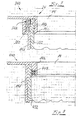
- the one as a takeover device 24 shows mounting device 340 formed on a molded jacket 14, is this mounting device 340 as a clamping device with a Clamping hose 348 executed, the mounting bar 332 against one Presses ring flange 14b of the molded jacket 14.
- the pressure hose 348 can be used hydraulically or pneumatically to exert the clamping action be expanded.
- the pressure hose 348 can do this from a relative dimensionally stable, but still to achieve the clamping effect be made elastically deformable material, for example a relative hard rubber compound.
- Another pressure hose 350 is located below the pressure hose 348 arranged, which can also be expanded hydraulically and / or pneumatically.
- This pressure hose 350 has the function of the circumferential groove 14c of the shaped jacket 14, between the side wall 14d and the ring flange 14b is formed where there is no mounting strip 332 in this annular groove 14c is inserted, against the penetration of concrete into this annular groove 14c Filling the mold cavity 18 to protect with concrete.
- the Pressure hose 350 can be expanded to a relatively large extent. It recommends therefore, him from a relatively elastic material, such as one soft rubber compound.
- the holder device 440 according to FIG. 8 differs from that 7 mainly by the fact that the there only pressure hose 448 provided both the clamping effect of the Pressure hose 348 as well as the sealing effect of the pressure hose 350 of the embodiment according to FIG. 7 takes over. Moreover, the pressure hose 448 arranged in the region of the ring flange 14b of the shaped jacket 14 and not in the area of its side wall 14d.
- the Holding device designed as a locking device 540.
- a sliding ring 552 which can be actuated via a control lug 552a in one Circumferential groove 14e of the shaped jacket 14 added.
- locking tabs 552b are provided, which in associated locking recesses 532d of the mounting strips 532 introduced can be.
- the assembly bar 532 enters the direction indicated by an arrow Area of a release portion 552c of the control ring 552 in which the cross-sections of control ring 552 and mounting bar 532 in 9b do not overlap, so that the mounting bar 532 can be withdrawn from the mounting device 540.
- an arrow Area of a release portion 552c of the control ring 552 in which the cross-sections of control ring 552 and mounting bar 532 in 9b do not overlap so that the mounting bar 532 can be withdrawn from the mounting device 540.
- a bracket device 640 in which such a rasterized design is realized is shown in Figs. 10a and 10b.
- Fig. 10b sees, a plurality of are distributed in the circumferential direction in the mold jacket 14 arranged recesses 14c 'formed in the mounting rails 632 can be introduced.
- Each insertion recess 14c ' is a clamping element 644 assigned that hydraulically and / or pneumatically against the Assembly bar 632 can be pressed.
- a sealing pin 656 is also provided which Plug recess 14c 'under the influence of a spring preload 656a normally closed, but when inserting the assembly bar 632 from this can be pushed back when the mounting bar 632 against a control bevel 656b of the sealing pin 656a starts.
- 11a and 11b is the mounting device 740 designed as a clamp hook connection.
- the Mounting bar 732 an elongated hole 732e with an enlarged end 732f and a narrowed end 732g is provided.
- a clamping hook element which is adjustable in the radial direction R.
- the in the interior 14a of the shell 14 protruding part of the clamping hook element 760 includes one Pin 760a, whose outer diameter is dimensioned slightly smaller than the width of the narrowed portion 732g of the elongated hole 732e and one End plate 760b, whose outer diameter is slightly smaller is as the width of the enlarged portion 732f of the elongated hole 732e, however, significantly larger than the width of the narrowed portion 732g.
- the extended one Section 732f of the elongated hole 732e in radial alignment with the receptacle 14e for the clamping hook element 760 this becomes the clamping hook element 760 by means of a preferably pneumatically or hydraulically operated Power device, through the opening 14e and the elongated hole 732e in Fig. 11b shifted to the right until a stop 760c on the outer peripheral surface of the shaped jacket 14 is present. If the mounting bar 732 in Fig. 11b shifted further upward, the narrowed section 732g arrives of the elongated hole 732b in engagement with the pin 760a of the clamping hook element 760.
- the clamping hook element 760 is again radially outwards, i.e. retracted to the left in FIG. 11b, so that the mounting strip 732 by means of the end plate 760b against the side wall 14d of the molding jacket 14 is pressed.
- Steps performed in reverse order are those described above Steps performed in reverse order.
- FIG. 12 is only intended to show that the set-up device 22 does not necessarily have a circumferential mounting ring corresponding to the retaining ring 22c shown in FIG. 1, but that it is also possible to have a plurality of support arms to be provided independently of one another normally in vertical axis extending setup axis r can be pivoted and if desired also independently in the direction of the setup axis r, i.e. normally in the vertical direction.
- bracket arms 22f On the free ends of these bracket arms 22f can be bracket devices for the arrangement of recess cores 20 or their mounting strips 32 may be provided.
- the main channel 12c and the Secondary channel 12d and, if desired, the rest of the bottom 12a and if necessary, even part of the inner surface of the side wall 12b of the Can be provided with a lining, to protect the concrete from attack by aggressive wastewater.
- These linings can for example be made of bricks, tiles, tiles or be made of plastic. These linings can also be used prepared the set-up device and by means of this set-up device in the Mold cavity 18 are introduced.
Landscapes
- Engineering & Computer Science (AREA)
- Manufacturing & Machinery (AREA)
- Chemical & Material Sciences (AREA)
- Ceramic Engineering (AREA)
- Mechanical Engineering (AREA)
- Manufacturing Of Tubular Articles Or Embedded Moulded Articles (AREA)
- Moulds, Cores, Or Mandrels (AREA)
Applications Claiming Priority (2)
| Application Number | Priority Date | Filing Date | Title |
|---|---|---|---|
| DE2000135864 DE10035864A1 (de) | 2000-07-24 | 2000-07-24 | Verfahren und Vorrichtung zum Fertigen von topfförmigen Betonteilen, insbesondere Schachtbodenstücken |
| DE10035864 | 2000-07-24 |
Publications (2)
| Publication Number | Publication Date |
|---|---|
| EP1175983A2 true EP1175983A2 (fr) | 2002-01-30 |
| EP1175983A3 EP1175983A3 (fr) | 2003-05-07 |
Family
ID=7649943
Family Applications (1)
| Application Number | Title | Priority Date | Filing Date |
|---|---|---|---|
| EP01117528A Withdrawn EP1175983A3 (fr) | 2000-07-24 | 2001-07-20 | Procédé et appareil pour la fabrication d'articles en béton en forme de cuve, en particulier d'éléments de trou d'homme |
Country Status (2)
| Country | Link |
|---|---|
| EP (1) | EP1175983A3 (fr) |
| DE (1) | DE10035864A1 (fr) |
Cited By (2)
| Publication number | Priority date | Publication date | Assignee | Title |
|---|---|---|---|---|
| WO2003086723A1 (fr) * | 2002-04-12 | 2003-10-23 | Wagener & Polascheck Vertriebsgesellschaft Mbh & Co. Kg | Procede de fabrication d'une partie de base de puits presentant des devers lateraux |
| EP4201622A1 (fr) * | 2021-12-21 | 2023-06-28 | Schöck Bauteile GmbH | Procédé et système de construction d'un coffrage côté bord |
Family Cites Families (3)
| Publication number | Priority date | Publication date | Assignee | Title |
|---|---|---|---|---|
| DE3611364A1 (de) * | 1986-04-04 | 1987-10-08 | Niemeyer Gmbh & Co Kg Soehne | Formvorrichtung fuer betonformkoerper |
| DE19540454A1 (de) * | 1995-10-30 | 1997-05-07 | Baumgaertner Maschf Gmbh | Verfahren und Anlage zur Herstellung von Schachtbodenstücken |
| DE19832112C1 (de) * | 1998-07-17 | 1999-10-28 | Merbeler Betonwerk Gmbh | Vorrichtung zur Kontrolle der Bestückung einer Form für Schachtteile mit Bestückungskörpern und Verfahren zur Bestückung einer Form für Schachtteile mit Bestückungskörpern |
-
2000
- 2000-07-24 DE DE2000135864 patent/DE10035864A1/de not_active Withdrawn
-
2001
- 2001-07-20 EP EP01117528A patent/EP1175983A3/fr not_active Withdrawn
Cited By (3)
| Publication number | Priority date | Publication date | Assignee | Title |
|---|---|---|---|---|
| WO2003086723A1 (fr) * | 2002-04-12 | 2003-10-23 | Wagener & Polascheck Vertriebsgesellschaft Mbh & Co. Kg | Procede de fabrication d'une partie de base de puits presentant des devers lateraux |
| EP4201622A1 (fr) * | 2021-12-21 | 2023-06-28 | Schöck Bauteile GmbH | Procédé et système de construction d'un coffrage côté bord |
| EP4201623A1 (fr) * | 2021-12-21 | 2023-06-28 | Schöck Bauteile GmbH | Procédé et système de construction d'un coffrage côté bord |
Also Published As
| Publication number | Publication date |
|---|---|
| DE10035864A1 (de) | 2002-02-07 |
| EP1175983A3 (fr) | 2003-05-07 |
Similar Documents
| Publication | Publication Date | Title |
|---|---|---|
| DE1601106A1 (de) | Kondensatorbuendel | |
| DE3110185A1 (de) | "formeinrichtung zur formgebung von betonteilen, insbesondere schachtringen, schachthaelsen od.dgl." | |
| EP2910687B1 (fr) | Dispositif et procédé de fabrication d'un tunnel présentant plusieurs tronçons de tunnel | |
| WO2017174432A1 (fr) | Dispositif de coffrage | |
| EP2934837A2 (fr) | Dispositif pour produire un élément de paroi préfabriquée de grande taille, en particulier comprenant au moins une couche de béton | |
| DE19912829B4 (de) | Anlage zum Herstellen von napfförmigen Betonformkörpern | |
| EP1175983A2 (fr) | Procédé et appareil pour la fabrication d'articles en béton en forme de cuve, en particulier d'éléments de trou d'homme | |
| DE2122874A1 (de) | Verfahren und Vorrichtung zum Herstellen dreidimensionaler, aus Beton oder dgl. geformter Bauelemente | |
| DE102007019383A1 (de) | Batterieschalung zur vertikalen Fertigung von flächigen Betonfertigteilen | |
| DE102004052395A1 (de) | Einschubverfahren von Maschineneinheiten in eine Produktionslinie | |
| DE4437518A1 (de) | Verfahren und Vorrichtung zum Herstellen von Betonteilen | |
| EP0963823A1 (fr) | Dispositif de manipulation pour moules utilisés dans la fabrication de regards en béton | |
| DE3038871A1 (de) | Formmaschine fuer betonfertigplatten | |
| DE4028884C2 (de) | Vorrichtung und Verfahren zum Herstellen von senkrecht stehenden Wandelementen aus Mauersteinen | |
| DE2315403C2 (de) | Fertiginstallationsvorrichtung | |
| DE3114122C2 (de) | Bausatz, bestehend aus einem Betonrahmen für die Aufnahme eines Kellerfensters, einem mit diesem zu verbindenden Lichtschachtunterteil und Verbindungsmitteln sowie Vorrichtung zur Herstellung eines Betonrahmens für einen solchen Bausatz | |
| EP0624693A2 (fr) | Procédé et dispositif de réalisation des ouvrages d'étanchéité en segment, dans la construction civile | |
| DE3515986C2 (de) | Verfahren zum Herstellen eines als Schachtunterteil oder Schachtboden dienenden Betonteils und Vorrichtung zur Durchführung des Verfahrens | |
| DE2322139C3 (de) | Batterieform und Verfahren zum Herstellen von Betonplatten | |
| AT410295B (de) | Anlage zum herstellen eines ringförmigen werkstückes aus beton, insbesondere eines schachtbodens | |
| DE932177C (de) | Vorrichtung zum Eindruecken von Nuten | |
| DE2252087C3 (de) | Schalung zur horizontalen Fertigung von Stahlbetonraumzellen, insbesondere von Fertiggaragen, welche einen Boden und eine offene Stirnseite aufweisen, und Verfahren zum Einbringen von Beton in die Schalung | |
| DE2913451A1 (de) | Verbesserungen an mechanischen schalungen fuer die schnelle errichtung von gebaeuden, vorzugsweise zur verwendung auf der baustelle | |
| EP0669192B1 (fr) | Procédé et dispositif pour la fabrication d'un tuyau d'avancement en béton armé | |
| DE2345207C2 (de) | Vorrichtung zum Bohren von Durchgangslöchern |
Legal Events
| Date | Code | Title | Description |
|---|---|---|---|
| PUAI | Public reference made under article 153(3) epc to a published international application that has entered the european phase |
Free format text: ORIGINAL CODE: 0009012 |
|
| AK | Designated contracting states |
Kind code of ref document: A2 Designated state(s): AT BE CH CY DE DK ES FI FR GB GR IE IT LI LU MC NL PT SE TR |
|
| AX | Request for extension of the european patent |
Free format text: AL;LT;LV;MK;RO;SI |
|
| PUAL | Search report despatched |
Free format text: ORIGINAL CODE: 0009013 |
|
| AK | Designated contracting states |
Designated state(s): AT BE CH CY DE DK ES FI FR GB GR IE IT LI LU MC NL PT SE TR |
|
| AX | Request for extension of the european patent |
Extension state: AL LT LV MK RO SI |
|
| RIC1 | Information provided on ipc code assigned before grant |
Ipc: 7B 28B 7/04 B Ipc: 7B 28B 7/00 B Ipc: 7B 28B 7/02 B Ipc: 7B 28B 7/16 A |
|
| 17P | Request for examination filed |
Effective date: 20031010 |
|
| AKX | Designation fees paid |
Designated state(s): AT BE CH CY DE DK ES FI FR GB GR IE IT LI LU MC NL PT SE TR |
|
| STAA | Information on the status of an ep patent application or granted ep patent |
Free format text: STATUS: THE APPLICATION IS DEEMED TO BE WITHDRAWN |
|
| 18D | Application deemed to be withdrawn |
Effective date: 20060419 |