EP4201623A1 - Procédé et système de construction d'un coffrage côté bord - Google Patents
Procédé et système de construction d'un coffrage côté bord Download PDFInfo
- Publication number
- EP4201623A1 EP4201623A1 EP22215650.7A EP22215650A EP4201623A1 EP 4201623 A1 EP4201623 A1 EP 4201623A1 EP 22215650 A EP22215650 A EP 22215650A EP 4201623 A1 EP4201623 A1 EP 4201623A1
- Authority
- EP
- European Patent Office
- Prior art keywords
- formwork
- edge
- component
- components
- plan
- Prior art date
- Legal status (The legal status is an assumption and is not a legal conclusion. Google has not performed a legal analysis and makes no representation as to the accuracy of the status listed.)
- Pending
Links
Images
Classifications
-
- B—PERFORMING OPERATIONS; TRANSPORTING
- B28—WORKING CEMENT, CLAY, OR STONE
- B28B—SHAPING CLAY OR OTHER CERAMIC COMPOSITIONS; SHAPING SLAG; SHAPING MIXTURES CONTAINING CEMENTITIOUS MATERIAL, e.g. PLASTER
- B28B7/00—Moulds; Cores; Mandrels
- B28B7/0002—Auxiliary parts or elements of the mould
- B28B7/0005—Mould identification means, e.g. by radio frequency identification device [RFID]
-
- B—PERFORMING OPERATIONS; TRANSPORTING
- B28—WORKING CEMENT, CLAY, OR STONE
- B28B—SHAPING CLAY OR OTHER CERAMIC COMPOSITIONS; SHAPING SLAG; SHAPING MIXTURES CONTAINING CEMENTITIOUS MATERIAL, e.g. PLASTER
- B28B17/00—Details of, or accessories for, apparatus for shaping the material; Auxiliary measures taken in connection with such shaping
- B28B17/0063—Control arrangements
- B28B17/0081—Process control
-
- B—PERFORMING OPERATIONS; TRANSPORTING
- B28—WORKING CEMENT, CLAY, OR STONE
- B28B—SHAPING CLAY OR OTHER CERAMIC COMPOSITIONS; SHAPING SLAG; SHAPING MIXTURES CONTAINING CEMENTITIOUS MATERIAL, e.g. PLASTER
- B28B7/00—Moulds; Cores; Mandrels
- B28B7/0002—Auxiliary parts or elements of the mould
- B28B7/0014—Fastening means for mould parts, e.g. for attaching mould walls on mould tables; Mould clamps
- B28B7/0017—Fastening means for mould parts, e.g. for attaching mould walls on mould tables; Mould clamps for attaching mould walls on mould tables
-
- B—PERFORMING OPERATIONS; TRANSPORTING
- B28—WORKING CEMENT, CLAY, OR STONE
- B28B—SHAPING CLAY OR OTHER CERAMIC COMPOSITIONS; SHAPING SLAG; SHAPING MIXTURES CONTAINING CEMENTITIOUS MATERIAL, e.g. PLASTER
- B28B7/00—Moulds; Cores; Mandrels
- B28B7/0002—Auxiliary parts or elements of the mould
- B28B7/0014—Fastening means for mould parts, e.g. for attaching mould walls on mould tables; Mould clamps
- B28B7/002—Fastening means for mould parts, e.g. for attaching mould walls on mould tables; Mould clamps using magnets
Definitions
- the invention relates to a method for creating an edge formwork on a surface for the production of a precast concrete component and a system for creating an edge formwork on a surface for the production of a precast concrete component.
- a formwork is usually formed from various existing formwork components, which is positioned on the surface by hand.
- the core idea of the present invention is to transform a plan for an edge formwork in such a way that the edge formwork is broken down into individual components and a component formwork plan is created.
- the component formwork plan that breaks down the components can be projected onto the surface and show the user where, how and which component should be positioned on the surface.
- the procedure can be carried out faster, since it does not require free positioning of components and the manufacture of auxiliary components from polystyrene.
- the user can be guided to position the available components in such a way that a targeted and quick arrangement of the components is possible.
- the invention provides a method for creating an edge formwork on a surface for the production of a precast concrete component, in which a device for projecting the edge formwork is used.
- the method comprises the steps of: a) reading in a plan for the edge formwork, b) creating a component formwork plan for replicating the formwork using components, and c) projecting the component formwork plan with a display of the individual components of the formwork onto the surface.
- precast concrete component includes a prefabricated component having concrete for use on a construction site, which is in particular flat, in particular cuboid, in design.
- the precast concrete component can have reinforcement, which can serve to reinforce the precast concrete component.
- the "precast concrete component” is cast from concrete. A flat form is formed with a formwork on the edge, into which concrete is filled.
- reinforcement includes a structure, also called reinforcement, which can usually be made of structural steel, reinforcing steel, reinforcing steel, glass fibers, carbon fibers, aramid and/or a combination of the materials mentioned.
- the reinforcement can have individual elements or components that are connected to one another.
- edge formwork includes an edge of a mold for the precast concrete component, in particular in one plane.
- the formwork at the edge thus forms, together with the surface on which the formwork at the edge is placed, a mold into which the concrete for producing the precast concrete component is introduced.
- the edge-side formwork usually exists made up of individual components that are positioned in relation to one another in such a way that the mold is created together with the surface.
- the components can be arranged in line or at an angle to one another, in particular 90°, on the surface to form the mould. For example, several molds can be arranged side by side on the surface.
- a component of an edge formwork forms the edge of a mold for a first precast concrete component with one of its sides and the edge of a mold for a second precast concrete component with another side.
- the components can be made of wood, plastic or metal or a combination of these materials. The use of metal may be preferred.
- the surface may be magnetic or magnetizable and the component may be magnetizable or magnetic to be fixed to the surface, respectively.
- the component(s) it is also additionally or alternatively possible for the component(s) to be mechanically fixed on the surface. Combinations of fixation options can be provided; it may also be possible to fix components on the surface in different ways.
- a "component" of the formwork can have a rod-like shape, in particular with a rectangular cross-section, a cuboid shape, in particular with a rectangular cross-section. There can be similar and different components of the formwork.
- a "Perimeter Formwork Plan” may result from the requirement to produce one or more precast concrete members of a given area. If several precast concrete components are to be produced on the surface, the formwork on the edge can complement one another in such a way that at least in sections one component of the formwork on the edge forms a border for at least two or more precast concrete components.
- the plan for the edge formwork is a plan in which the surfaces of the prefabricated concrete components to be produced specify the edge formwork in its entirety - without specifying components.
- the term “reading in a plan for the edge-side formwork” includes an electronic conversion of the plan for the edge-side formwork into data and/or signals that can be processed with an arithmetic unit.
- the data and/or signals reflect an embodiment of a plan for an edge casing.
- a plan for edge-side formwork can be read in such that the spatial points of the edges of the precast concrete components to be produced that are to be produced on the surface are stored.
- the term “device for projecting the edge casing” encompasses a device that can optically project a edge casing in such a way that the individual components of the edge casing can be visually resolved by a user.
- the device can have a projector-like unit that displays the image of the edge casing with the components (component casing plan). It can be provided that the device for projecting the edge casing is physically in a housing, in particular a freely programmable, arithmetic unit (machine or electronic circuit), for example in the form of a (micro)processor, (micro)controller or the like , having.
- the process of reading in a plan of the edge-side formwork and the calculation into the edge-side formwork with individual components can be carried out.
- the device for projecting the edge-formwork receives signals or data from an arithmetic unit which is present outside a housing of the device for projecting the edge-formwork and does not belong to the device for projecting the edge-formula per se.
- Said arithmetic unit can be connected functionally, in particular bidirectionally, to the device for projecting the edge-side cladding wirelessly or by cable.
- the arithmetic unit can control the device for projecting the edge formwork, so that the device for projecting the edge formwork does not have to have its own control unit physically in a housing.
- An arithmetic unit external to the device for projecting the edge formwork, which is functionally connected to the device for projecting the edge formwork, can carry out the reading of the plan for the edge formwork.
- the device for projecting the edge formwork can have a "device for detecting the surface surroundings" which can have at least one sensor with which the surface and the edge region of the surface can be detected.
- the device for projecting the edge cladding can be connected wirelessly or by cable to the device for detecting the surface environment in order to exchange data and/or signals, in particular bidirectionally.
- the senor of the device for detecting the surface environment can be any technical component with which the surface environment can be detected.
- the sensor can be a technical component with which the position and/or location of the edge-side formwork or the individual components of the edge-side formwork can be determined on the surface. With knowledge of the position and/or location of the components, for example, a release for the supply of concrete into the mold or the casing on the surface at the edge can take place.
- the sensor of the device for detecting the surface environment can be an optical sensor, an acoustic sensor (sound sensor), a mechanical/tactile sensor and/or an inductive sensor. More than one sensor or more than one type of sensor can also be provided. If more than one sensor is provided, the sensors can be of different or the same type.
- a sensor can preferably be a combination of the aforementioned configurations of the sensors, in which case a configuration with two or more types of sensors can be preferred. Different configurations of casing and/or casing element(s) can be detected by means of different sensors and/or a combination of sensor types in one sensor.
- the sensor can in particular be an optical sensor. It is possible, for example, for the device for detecting the surface environment to optically detect the casing or one or more components.
- the sensor may scan the surface environment optically. The scanning can take place according to a pattern, for example in rows and/or columns, according to the principle of a transit time measurement.
- an optical scanning of the surface environment takes place or supports this by projecting a pattern onto the surface environment.
- a predetermined pattern can be projected into the surface environment, where the projection of the pattern can be detected. From the deviations between the predetermined pattern and the projection, the location (position) and/or the location of the edge casing or the components of the edge casing on the surface can be determined.
- a “component formwork plan” is understood to mean information corresponding to a peripheral formwork constructed according to a plan formwork and containing the components of the formwork leading to the plan formwork, in order to form the plan formwork "recreate”.
- the term “creating” a component formwork plan is understood to mean the transformation of the plan of the edge formwork into a “component formwork plan”.
- the "creating” can be done by means of an arithmetic unit which knows the components to be used, for example from a database accessible to the arithmetic unit.
- the surface can be the surface of a table of a circulation system. In this way, a simple way of creating an edge casing can be created for a circulating system, with which the user is supported in a simple manner.
- the individual components are highlighted separately in the display. This allows the user to be further supported. For example, adjacent components may have a different color, border, fill, or the like. It is also possible for the display and/or the component to represent or have a code, by means of which the component or similar components can be identified by the user.
- the coding can be a number, a bar code, a sequence of numbers, a character string, a sequence of letters or the like.
- the display is supported by means of a display device that can be worn by a user.
- the display device can be embodied as a spectacle-like display device or as a display or monitor-like display device that can be held in one or more hands.
- the display or monitor-like display device can be provided in addition to a projection of the component wiring diagram and further resolve the components of the component wiring diagram or display additional information about the components.
- a component per se and/or information about the component can be specified on the display device.
- a spectacle-like display device can, if the display is projected into the spectacle lens or the like, enable the environment to be perceived in addition to the information displayed, so that the (desired) position of the component (component wiring plan) can be determined while the user is positioning the component the user can be recorded.
- a glasses-type display device can enable the user to be unaffected by holding the display device.
- the creation of the component formwork plan is optimized in relation to components present in a warehouse. This enables good utilization and optimal use of the stored components.
- the components present in the warehouse can be stored, for example, in a database of an arithmetic unit.
- the display indicates a storage location.
- the information can be stored in a database of the arithmetic unit and be used.
- the display can take place alternatively or additionally on the display device, so that the user can, for example, carry the information with him when going to the warehouse.
- the display occurs at least partially in a user's glasses.
- an information display that has little negative impact on the user can be created.
- the display takes place at least partially on a mobile display of a portable (display) device.
- a flexible additional display option can be created in which, for example, a simple input option can also be present.
- the display can be designed as a touch screen. It is also possible to provide a mechanical input option on the mobile display, in particular in the form of a trackball, keys or the like.
- the individual components are displayed in a warehouse for the components.
- the display is made by means of a display device that is stationary in the warehouse, for example, and that does not need to be carried by the user.
- each component has an identification means, by means of which the component can be identified. This can create the possibility of identifying the components by the user and/or the device for detecting the surface environment.
- the sensors described can be present for the respective corresponding identification means.
- a database is maintained in which entries are updated regarding the presence, location and/or status of a component.
- additional information can be present in the database, which can provide additional added value for the user. For example, it can be taken into account whether the component should be used elsewhere, taken to another location that is not being used and/or the component should be replaced.
- the invention also provides a system for creating an edge formwork on a surface for the production of a precast concrete component.
- the system has a device for projecting the edge formwork, the device for projecting the edge formwork and/or an arithmetic unit functionally connected to the device for projecting the edge formwork being configured to read in a plan of the edge formwork, a create a component formwork plan for replicating the formwork using components of the formwork, and display the component formwork plan with a display of each component of the formwork on the interface.
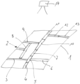
- Fig. 1 shows a surface 1 on which an edge formwork 2 is arranged in order to produce precast concrete components.
- the formwork 2 at the edge forms, together with the surface 1, molds into which concrete can be poured to produce the precast concrete components.
- precast concrete components can be produced on the surface 1, for which purpose several molds are present.
- the edge casing 2 for the molds is constructed using individual components 3 , 4 , 5 , 6 , 7 , 8 , 9 , 10 , 11 , 12 , 13 .
- a device 14 for projecting the edge-side formwork 2 which generates a component formwork plan with a display of the individual components 3, 4, 5, 6, 7, 8, 9 , 10, 11, 12, 13 of the casing 2 are projected onto the surface 1.
Landscapes
- Engineering & Computer Science (AREA)
- Chemical & Material Sciences (AREA)
- Ceramic Engineering (AREA)
- Mechanical Engineering (AREA)
- Manufacturing & Machinery (AREA)
- Automation & Control Theory (AREA)
- Moulds, Cores, Or Mandrels (AREA)
Applications Claiming Priority (1)
| Application Number | Priority Date | Filing Date | Title |
|---|---|---|---|
| EP21216682.1A EP4201622A1 (fr) | 2021-12-21 | 2021-12-21 | Procédé et système de construction d'un coffrage côté bord |
Publications (1)
| Publication Number | Publication Date |
|---|---|
| EP4201623A1 true EP4201623A1 (fr) | 2023-06-28 |
Family
ID=79019200
Family Applications (2)
| Application Number | Title | Priority Date | Filing Date |
|---|---|---|---|
| EP21216682.1A Pending EP4201622A1 (fr) | 2021-12-21 | 2021-12-21 | Procédé et système de construction d'un coffrage côté bord |
| EP22215650.7A Pending EP4201623A1 (fr) | 2021-12-21 | 2022-12-21 | Procédé et système de construction d'un coffrage côté bord |
Family Applications Before (1)
| Application Number | Title | Priority Date | Filing Date |
|---|---|---|---|
| EP21216682.1A Pending EP4201622A1 (fr) | 2021-12-21 | 2021-12-21 | Procédé et système de construction d'un coffrage côté bord |
Country Status (1)
| Country | Link |
|---|---|
| EP (2) | EP4201622A1 (fr) |
Citations (9)
| Publication number | Priority date | Publication date | Assignee | Title |
|---|---|---|---|---|
| JPH05323875A (ja) * | 1992-05-22 | 1993-12-07 | Fujita Corp | コンクリート用型枠の管理用ラベル |
| JPH06272376A (ja) * | 1993-01-13 | 1994-09-27 | Toda Constr Co Ltd | 打ち込み金物のスミ出し方法 |
| EP1175983A2 (fr) * | 2000-07-24 | 2002-01-30 | BAUMGÄRTNER GmbH MASCHINENFABRIK | Procédé et appareil pour la fabrication d'articles en béton en forme de cuve, en particulier d'éléments de trou d'homme |
| US20060016957A1 (en) * | 2004-03-05 | 2006-01-26 | Karsten Hofmann | Systems and methods for displaying images and processing work pieces |
| DE102006051835B4 (de) * | 2006-11-03 | 2008-07-17 | Weckenmann Anlagentechnik Gmbh & Co. Kg | Schalungsroboteranordnung zur Herstellung von Betonfertigteilen |
| JP2014077241A (ja) * | 2012-10-09 | 2014-05-01 | Just Will Co Ltd | 打設コンクリート強度管理システム |
| DE102016105480A1 (de) * | 2016-03-23 | 2017-09-28 | Jürgen Gehrmann | Verfahren und System zum Installieren, Verwalten und/oder Warten von Komponenten in einem Gebäudekomplex |
| WO2021110228A1 (fr) * | 2019-12-06 | 2021-06-10 | Connovate Aps | Système de moule modulaire |
| CN113084993A (zh) * | 2021-03-23 | 2021-07-09 | 山东城开远大装配式建筑有限公司 | 一种预制楼板模具及预埋件用定位装置 |
Family Cites Families (1)
| Publication number | Priority date | Publication date | Assignee | Title |
|---|---|---|---|---|
| DE102020201563A1 (de) * | 2020-02-07 | 2021-08-12 | Peri Gmbh | Einlageelement für einen Kunststoffschalungspaneelrahmen |
-
2021
- 2021-12-21 EP EP21216682.1A patent/EP4201622A1/fr active Pending
-
2022
- 2022-12-21 EP EP22215650.7A patent/EP4201623A1/fr active Pending
Patent Citations (9)
| Publication number | Priority date | Publication date | Assignee | Title |
|---|---|---|---|---|
| JPH05323875A (ja) * | 1992-05-22 | 1993-12-07 | Fujita Corp | コンクリート用型枠の管理用ラベル |
| JPH06272376A (ja) * | 1993-01-13 | 1994-09-27 | Toda Constr Co Ltd | 打ち込み金物のスミ出し方法 |
| EP1175983A2 (fr) * | 2000-07-24 | 2002-01-30 | BAUMGÄRTNER GmbH MASCHINENFABRIK | Procédé et appareil pour la fabrication d'articles en béton en forme de cuve, en particulier d'éléments de trou d'homme |
| US20060016957A1 (en) * | 2004-03-05 | 2006-01-26 | Karsten Hofmann | Systems and methods for displaying images and processing work pieces |
| DE102006051835B4 (de) * | 2006-11-03 | 2008-07-17 | Weckenmann Anlagentechnik Gmbh & Co. Kg | Schalungsroboteranordnung zur Herstellung von Betonfertigteilen |
| JP2014077241A (ja) * | 2012-10-09 | 2014-05-01 | Just Will Co Ltd | 打設コンクリート強度管理システム |
| DE102016105480A1 (de) * | 2016-03-23 | 2017-09-28 | Jürgen Gehrmann | Verfahren und System zum Installieren, Verwalten und/oder Warten von Komponenten in einem Gebäudekomplex |
| WO2021110228A1 (fr) * | 2019-12-06 | 2021-06-10 | Connovate Aps | Système de moule modulaire |
| CN113084993A (zh) * | 2021-03-23 | 2021-07-09 | 山东城开远大装配式建筑有限公司 | 一种预制楼板模具及预埋件用定位装置 |
Non-Patent Citations (1)
| Title |
|---|
| "LASER PROJIZIERT KONTUR VON BETONFERTIGTEILEN / LASER PROJECTED CONTOUR OF PRECAST CONCRETE PARTS", BFT INTERNATIONAL, BAUVERLAG, GUTERSLOH, DE, vol. 62, no. 8, 1 August 1996 (1996-08-01), pages 154/155, XP000622089, ISSN: 0373-4331 * |
Also Published As
| Publication number | Publication date |
|---|---|
| EP4201622A1 (fr) | 2023-06-28 |
Similar Documents
| Publication | Publication Date | Title |
|---|---|---|
| DE112011102645B4 (de) | Steuerungsvorrichtung für eine Formmaschine und Herstellungsverfahren für geformte Artikel | |
| DE112012007233B4 (de) | Numerische-Steuerung-Vorrichtung | |
| CN107341290B (zh) | 基于bim的梁板预制与现浇结构工程量提取系统及方法 | |
| DE2724075A1 (de) | System zur optischen wiedergabe von symbolen, zeichen und darstellungen, insbesondere fuer den layout von anzeigen in zeitungen u.dgl. | |
| DE102009007477A1 (de) | Modellaufbau einer Fertigungsstätte mit maßstabsgerechten Modellen von Fertigungseinrichtungen sowie Verfahren zur Eingabe eines räumlichen Aufbaus von Fertigungseinrichtungen in ein rechnergestütztes Planungsprogramm | |
| CN112487526A (zh) | 一种装配式预制叠合板深化图自动绘图方法 | |
| DE102019108689A1 (de) | Verfahren und Vorrichtung zum Steuern einer Materialumschlags- und/oder Baumaschine | |
| DE102018000017B4 (de) | Maschinenvorrichtung, die Stöße erlernt, die eine Lehrvorrichtung erhält, Stoßverhin-derungssystem einer Lehrvorrichtung und Maschinenlernverfahren | |
| DE102019117877A1 (de) | Roboterprogrammgenerierungsvorrichtung | |
| EP4201623A1 (fr) | Procédé et système de construction d'un coffrage côté bord | |
| DE102017105597B4 (de) | Bearbeitungsprogrammerzeugungsvorrichtung | |
| JPH068342A (ja) | 三次元形状造形物の製造方法 | |
| DE102016003898A1 (de) | Numerische Steuerung mit Programmanzeigefunktion unter Verwendung einer Vielzahl von Bildern | |
| DE202015009829U1 (de) | Mensch-Maschine-Schnittstelle, die dazu geeignet ist, mit einer Einrichtung für die Bearbeitung von Werkstücken mit einem Gerät zur Werkstückermittlung zur automatischen Programmierung des Bearbeitungszyklus verbunden zu werden | |
| JP3082607B2 (ja) | 曲面プレキャストコンクリート版の成形用型枠装置 | |
| DE112014003146T5 (de) | Systemkonstruktionsunterstützungsvorrichtung, Verfahren und Speichermedium | |
| EP4201621A1 (fr) | Construction d'un coffrage | |
| DE3347332C2 (fr) | ||
| DE102023103635A1 (de) | Computersystem für die Anzeige von Probenbildern, Mikroskopsystem und Verfahren hierfür | |
| DE112017001054T5 (de) | Videowiedergabevorrichtung, videowiedergabeverfahren, und programm | |
| EP0060413A1 (fr) | Appareil à dessiner | |
| DE3420806A1 (de) | Verfahren zum bewehren von betonplatten sowie vorrichtung zur durchfuehrung des verfahrens | |
| DE112022002344T5 (de) | Datenverarbeitungseinrichtung, programm und datenverarbeitungsverfahren | |
| DE102020209210A1 (de) | Steuervorrichtung und steuerverfahren | |
| EP4202145A1 (fr) | Procédé et système de fabrication d'une armature d'un élément préfabriqué en béton |
Legal Events
| Date | Code | Title | Description |
|---|---|---|---|
| PUAI | Public reference made under article 153(3) epc to a published international application that has entered the european phase |
Free format text: ORIGINAL CODE: 0009012 |
|
| STAA | Information on the status of an ep patent application or granted ep patent |
Free format text: STATUS: THE APPLICATION HAS BEEN PUBLISHED |
|
| AK | Designated contracting states |
Kind code of ref document: A1 Designated state(s): AL AT BE BG CH CY CZ DE DK EE ES FI FR GB GR HR HU IE IS IT LI LT LU LV MC ME MK MT NL NO PL PT RO RS SE SI SK SM TR |
|
| STAA | Information on the status of an ep patent application or granted ep patent |
Free format text: STATUS: REQUEST FOR EXAMINATION WAS MADE |
|
| 17P | Request for examination filed |
Effective date: 20231227 |
|
| RBV | Designated contracting states (corrected) |
Designated state(s): AL AT BE BG CH CY CZ DE DK EE ES FI FR GB GR HR HU IE IS IT LI LT LU LV MC ME MK MT NL NO PL PT RO RS SE SI SK SM TR |
|
| STAA | Information on the status of an ep patent application or granted ep patent |
Free format text: STATUS: EXAMINATION IS IN PROGRESS |
|
| 17Q | First examination report despatched |
Effective date: 20250123 |