EP1176793A2 - Système de balayage et procédé pour la balayage d'images vers un emplacement éloigné - Google Patents
Système de balayage et procédé pour la balayage d'images vers un emplacement éloigné Download PDFInfo
- Publication number
- EP1176793A2 EP1176793A2 EP01305485A EP01305485A EP1176793A2 EP 1176793 A2 EP1176793 A2 EP 1176793A2 EP 01305485 A EP01305485 A EP 01305485A EP 01305485 A EP01305485 A EP 01305485A EP 1176793 A2 EP1176793 A2 EP 1176793A2
- Authority
- EP
- European Patent Office
- Prior art keywords
- scanner
- destination location
- document
- icon
- location
- Prior art date
- Legal status (The legal status is an assumption and is not a legal conclusion. Google has not performed a legal analysis and makes no representation as to the accuracy of the status listed.)
- Ceased
Links
Images


Classifications
-
- H—ELECTRICITY
- H04—ELECTRIC COMMUNICATION TECHNIQUE
- H04N—PICTORIAL COMMUNICATION, e.g. TELEVISION
- H04N1/00—Scanning, transmission or reproduction of documents or the like, e.g. facsimile transmission; Details thereof
- H04N1/00127—Connection or combination of a still picture apparatus with another apparatus, e.g. for storage, processing or transmission of still picture signals or of information associated with a still picture
- H04N1/00204—Connection or combination of a still picture apparatus with another apparatus, e.g. for storage, processing or transmission of still picture signals or of information associated with a still picture with a digital computer or a digital computer system, e.g. an internet server
- H04N1/00236—Connection or combination of a still picture apparatus with another apparatus, e.g. for storage, processing or transmission of still picture signals or of information associated with a still picture with a digital computer or a digital computer system, e.g. an internet server using an image reading or reproducing device, e.g. a facsimile reader or printer, as a local input to or local output from a computer
- H04N1/00241—Connection or combination of a still picture apparatus with another apparatus, e.g. for storage, processing or transmission of still picture signals or of information associated with a still picture with a digital computer or a digital computer system, e.g. an internet server using an image reading or reproducing device, e.g. a facsimile reader or printer, as a local input to or local output from a computer using an image reading device as a local input to a computer
-
- H—ELECTRICITY
- H04—ELECTRIC COMMUNICATION TECHNIQUE
- H04N—PICTORIAL COMMUNICATION, e.g. TELEVISION
- H04N1/00—Scanning, transmission or reproduction of documents or the like, e.g. facsimile transmission; Details thereof
- H04N1/00127—Connection or combination of a still picture apparatus with another apparatus, e.g. for storage, processing or transmission of still picture signals or of information associated with a still picture
- H04N1/00204—Connection or combination of a still picture apparatus with another apparatus, e.g. for storage, processing or transmission of still picture signals or of information associated with a still picture with a digital computer or a digital computer system, e.g. an internet server
- H04N1/00236—Connection or combination of a still picture apparatus with another apparatus, e.g. for storage, processing or transmission of still picture signals or of information associated with a still picture with a digital computer or a digital computer system, e.g. an internet server using an image reading or reproducing device, e.g. a facsimile reader or printer, as a local input to or local output from a computer
-
- H—ELECTRICITY
- H04—ELECTRIC COMMUNICATION TECHNIQUE
- H04N—PICTORIAL COMMUNICATION, e.g. TELEVISION
- H04N2201/00—Indexing scheme relating to scanning, transmission or reproduction of documents or the like, and to details thereof
- H04N2201/0008—Connection or combination of a still picture apparatus with another apparatus
- H04N2201/0074—Arrangements for the control of a still picture apparatus by the connected apparatus
Definitions
- the present invention generally relates to computers and software, and more particularly, to a scan system and method for providing users the ability to quickly and efficiently transfer documents and images from a scanner to a remote location.
- a key difficulty with saving image documents to a server on the Internet or Intranet is that of simplicity for novice users.
- the prior solution for providing web page construction of scanned documents requires the user to (1) scan the document (2) connect to a remote server; (3) log-on to the remote server; (4) manually specify the destination folder; and (5) manually transfer the document to the remote server.
- each of the previous steps is a complicated and time-consuming task for even the most experienced scanner owner.
- image-acquiring devices include, for example, but are not limited to, digital cameras, digital videocassette recorder equipment, and the like.
- the problems for digital cameras, digital video cassette recorder equipment, and the like include requiring proper adapters and cables for connecting to a target folder on a computer system, maintaining the correct version of device software for image execution, and the like, in addition to the problems mentioned above.
- the present invention is generally directed to a scan system and method for providing users the ability to quickly and efficiently transfer documents and images from a scanner to a remote location.
- the scan system can be implemented as follows.
- the scan system includes a scanner and a transferring mechanism.
- the scanner is provided to generate a scanned document or image.
- a transferring mechanism initiates the scanning of the document or image, connects to a destination location and transfers the scanned document or image to the destination location for storage.
- the present invention can also be viewed as providing a method for scanning documents directly to a destination location.
- the method can be broadly summarized by the following steps: (1) selecting a scanner icon; (2) accociatng the icon with the destination location; (3) scanning a document or image using a scanner; and (4) automatically transferring the scanned document to the destination location for storage.
- the present invention provides the functionality of a single drag and drop solution that enables a user to initiate scanning a document on a scanner, connecting to a remote location and saving the scanned document in a folder with just one move of the mouse.
- FIG. 1 is a block diagram of possible system configurations that illustrate the flexibility and platform independence of the present invention. While the scan system of the invention can take many forms, the diagram of FIG. 1 illustrates a plurality of scan devices 16 and 21, that are directly connected to a network 32, for example, but not limited to, a dial-in, LAN, WAN, PSTN, Intranet and Internet communication links (18 and 24). Each of the scan systems in FIG. 1 is uniquely illustrated to emphasize that scan systems maybe comprised of diverse hardware platforms.
- the scan systems maybe comprised of a scanner 22 that is connected to a computer 21. This allows the computer 21 to execute a scan system that interacts with scanner 22.
- Network 18 may be, for example, an Ethernet type network (e.g ., 10 BASE 2, 10 BASE 5, 10 BSAF, 10 BASE-T, base band network, a coaxial cable, a dial-in, LAN, WAN, PSTN, Intranet or Internet.
- Ethernet type network e.g ., 10 BASE 2, 10 BASE 5, 10 BSAF, 10 BASE-T, base band network, a coaxial cable, a dial-in, LAN, WAN, PSTN, Intranet or Internet.
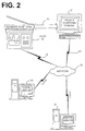
- FIG. 2 Illustrated in FIG. 2 is a more detailed figure showing that a scanner 16 may be connected directly to a user computer 21 or with an optional keyboard and display directly connected via a link 18 to a network 32.
- the stand-alone scanner 16 includes the scan system 100 that is specifically designed to operate on stand-alone scanner systems.
- Some stand-alone scanners 16 can provide for scanned documents or images directly to a LAN, WAN, Intranet or Internet, local server site 26 or remote server site 31.
- the stand-alone scanner 16 may include a keypad and a limited display.
- the user presets the destination network site. The identification of this preset destination network site can be downloaded via the communication links 18 or 23, or programmed utilizing standard methods.
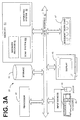
- a computer system that employs the scan system 100 may also include a browser program 53 (e.g. , Netscape, Internet Explorer, or other browser type program) for use in accessing locations on a network 32.
- the browser program 53 provides for a variety of hardware platforms. Browsers are most commonly recognized for their utility for accessing information over the Internet 32.
- a browser is a device or platform that allows a user to view a variety of service collections.
- the browser program 53 retrieves information from a remote server 31 or local server 26, using HTTP.
- the browser program 53 interprets HTML code, formats the code, and displays the interpreted result on a workstation display, such as display 46.
- the browser program 53 resides in computer memory 51 and accesses communication facilities modem 47 to bring resources from the network 32 to the user's browser using the modem.
- the user In order to find a resource, the user should know the network location (i.e ., site) of the resource denoted by a network location identifier or URL. These identifiers are often cryptic, following very complex schemes and formats in their naming conventions.
- Computer systems identify, access, and process these resources desired by a user by using the processor 41, storage device 42, and memory 51 with an operating system 52 and browser program 53.
- the processor accepts data from memory 51 and storage 42 over the local interface 43, for example, one or more buses.
- Direction from the user can be signaled by using one or more input devices, for example, mouse 44 and keyboard 45, as well as by actuating a pushbutton on the front of the scanner itself.
- the actions input and result output are displayed on the display terminal 46.
- FIG. 3A is the scan system 100 of the present invention situated in a user's computer system 12. This scan system 100 will be further explained hereafter with regard to Figs. 4-6.
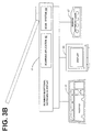
- FIG. 3B Illustrated in FIG. 3B is a block diagram of a stand-alone scanner 16 including the scanning application 62.
- Scanner 16 usually includes a processor (not shown) and a memory (not shown) that utilizes a scanning application 62 to control the scanner and an optical input device (not shown).
- the processor accepts data from the optical input device and memory over a bus (not shown).
- Direction from the user can be signaled by using the input devices such as a keypad 65, as well as by actuating a pushbutton (not shown) on the front of the scanner itself.
- the actions input and result output may be displayed on the optional display terminal 66.
- the stand-alone scanner 16 also includes a modem or network card 67 to establish communication with the remote server 31 on network 32. Scanner 16 can also be implemented utilizing non-processor circuitry.
- FIG. 3B Also illustrated in FIG. 3B is the scan system 100 of the present invention situated in the stand-alone scanner 16.
- This scan system 100 resides in hardware, software or firmware of the stand-alone scanner 16.
- the scan system 100 will be further explained hereafter with regard to FIGs. 4-6.
- FIG. 4 illustrated is an example of a scan system 100 executing on a computer system 12 or stand-alone scanner 16.
- the first step of scan system 100 is to initialize itself at step 101. If the scan system 100 is implemented using a browser program 53 (FIG. 3A), scan system 100 is initialized in that environment. The scan system 100 then directs the scanner 16 or 22 to initialize the scanning application 62 (FIG. 3B) at step 101.
- the scanning application 62 is the general purpose scanning software that enables a scanning system 16 or 22 to acquire a digitized image. The scanning application 62 is utilized to control the scanner and the optical input device to create the digitized image.
- the scan system 100 determines whether an automatic document feeder (ADF) is connected and ready. If it is determined at step 103 that the ADF is not connected or is not ready, the scan system 100 then proceeds to step 107 to proceed with the common scanning user interface of the scanning application 62. If it is determined at step 103 that the ADF is connected and ready, the scan system 100 executes the display ADF user interface process at step 104.
- the display ADF user interface process is herein defined in further detail with regard to FIG. 5.
- the scan system 100 After execution of the display ADF user interface process 104, the scan system 100 then executes the document drag and drop process at step 105.
- the document drag and drop process is herein defined in further detail with regard to FIG. 6.
- the scan application is terminated on the scanner system at step 106.
- the scan system 100 exits from the stand alone scanner or on the computer.
- the display user interface process 120 is first initialized at step 121.
- the display user interface process 120 displays a list of available servers, and an icon or picture representing the automatic document feeder or the document image to be scanned.
- the list of available servers can be either a text list in a graphical user interface system or can comprise icons representative of the available destination servers.
- the display user interface process 120 determines whether the user has chosen a server from the available list of servers. If it is determined at step 123 that the user has not chosen a server from the list of available servers, the display user interface process 120 then utilizes the default server as the destination location at step 124. After setting up the default server or if the user did select a server from the list of available servers, the display user interface process 120 then establishes a connection at step 125, with either the selected server, or if no server was selected at step 123, the default server.
- the display user interface process 120 determines whether the connection to the destination server attempted at step 125 was completed successfully. If the attempt to connect to the server at step 125 was not successful, the display user interface process displays an error message and switches to scanning off-line at step 127. After displaying the error message, the display user interface process 120 exits at step 139.
- the display user interface process 120 If it is determined at step 126 that the connection attempted at step 125 was successful, the display user interface process 120 then queries the destination server for any personal and available folders for storage at step 131. At step 132, the display user interface process 120 displays the icons representing available folders. At step 133, the display user interface process 120 indicates that the automatic document feeder is ready for use. The display user interface process 120 then exits at step 139.
- Illustrated in FIG. 6 is an example of a flow diagram of the document drag and drop process 140.
- the user initializes the document drag and drop process 140 by dragging an icon representing the automatic document feeder or document into one of the personal folder icons.
- the icons representing the automatic document feeder or documents were previously displayed at step 132 (FIG. 5).
- the document drag and drop process 140 then commands the scanner to scan the document.
- step 143 it is determined whether it is necessary to convert the scanned document or image into a different document format. If it is not necessary to convert the scanned document into a different document format type, the document drag and drop process 140 proceeds to step 145. If it is necessary to convert the scanned document into a different document format, the document drag and drop process 140 converts the scanned document to the different document format at step 144.
- the document drag and drop process 140 transfers the scanned document to a remote server at step 145.
- This transfer preferably utilizes the FTP protocol to transfer the document, however, other methods of transferring the document are feasible.
- the documents are then stored in the selected folder.
- the document drag and drop process 140 determines whether the transfer was successful. If the transfer at step 145 was successful, the drag and drop process 140 displays a transfer success message at step 152. If the transfer attempted at step 145 was determined not to be successful, the document drag and drop process 140 then displays a transfer error message at step 151.
- the document drag and drop process 140 After displaying either a transfer error or success message at step 151 and 152, respectively, the document drag and drop process 140 then displays a message indicating that the ADF automatic document feeder is now ready for continued use at step 153.
- the display message preferably utilizes the scrolling text to display the message, however, other methods of displaying the message are feasible.
- the document drop and drag process 140 then exits at step 159.
- the scan system 100 comprises an ordered listing of executable instructions for implementing logical functions and can be embodied in any computer-readable medium for use by or in connection with an instruction execution system, apparatus, or device, such as a computer-based system, processor-containing system, or other system that can fetch the instructions from the instruction execution system, apparatus, or device and execute the instructions.
- a "computer-readable medium" can be any means that can contain, store, communicate, propagate, or transport the program for use by or in connection with the instruction execution system, apparatus, or device.
- the computer readable medium can be, for example, but not limited to, an electronic, magnetic, optical, electromagnetic, infrared, or semiconductor system, apparatus, device, or propagation medium. More specific examples (a nonexhaustive list) of the computer-readable medium would include the following: an electrical connection (electronic) having one or more wires, a portable computer diskette (magnetic), a random access memory (RAM) (magnetic), a read-only memory (ROM) (magnetic), an erasable programmable read-only memory (EPROM or Flash memory) (magnetic), an optical fiber (optical), and a portable compact disc read-only memory (CDROM) (optical).
- an electrical connection electronic having one or more wires
- a portable computer diskette magnetic
- RAM random access memory
- ROM read-only memory
- EPROM or Flash memory erasable programmable read-only memory
- CDROM portable compact disc read-only memory
- the computer-readable medium could even be paper or another suitable medium upon which the program is printed, as the program can be electronically captured, via for instance optical scanning of the paper or other medium, then compiled, interpreted or otherwise processed in a suitable manner if necessary, and then stored in a computer memory.
- each block represents a module, segment, or portion of code, which comprises one or more executable instructions for implementing the specified logical function(s).
- the functions noted in the blocks may occur out of the order. For example, blocks shown in succession may in fact be executed substantially concurrently or the blocks may sometimes be executed in the reverse order, depending upon the functionality involved, as described herein above.
Landscapes
- Engineering & Computer Science (AREA)
- General Engineering & Computer Science (AREA)
- Computing Systems (AREA)
- Multimedia (AREA)
- Signal Processing (AREA)
- Facsimiles In General (AREA)
Applications Claiming Priority (2)
| Application Number | Priority Date | Filing Date | Title |
|---|---|---|---|
| US626063 | 2000-07-26 | ||
| US09/626,063 US7106464B1 (en) | 2000-07-26 | 2000-07-26 | Scan system and method for scanning images to a remote location |
Publications (2)
| Publication Number | Publication Date |
|---|---|
| EP1176793A2 true EP1176793A2 (fr) | 2002-01-30 |
| EP1176793A3 EP1176793A3 (fr) | 2003-04-02 |
Family
ID=24508795
Family Applications (1)
| Application Number | Title | Priority Date | Filing Date |
|---|---|---|---|
| EP01305485A Ceased EP1176793A3 (fr) | 2000-07-26 | 2001-06-25 | Système de balayage et procédé pour le balayage d'images vers un emplacement éloigné |
Country Status (3)
| Country | Link |
|---|---|
| US (1) | US7106464B1 (fr) |
| EP (1) | EP1176793A3 (fr) |
| TW (1) | TW595200B (fr) |
Families Citing this family (18)
| Publication number | Priority date | Publication date | Assignee | Title |
|---|---|---|---|---|
| JP4428844B2 (ja) * | 1999-10-01 | 2010-03-10 | キヤノン株式会社 | 情報処理装置、データ処理方法及び記録媒体 |
| CN102289832B (zh) * | 2000-06-09 | 2014-08-20 | 精工爱普生株式会社 | 图像指定文件的制作和使用了该文件的图像的播放 |
| US7019858B1 (en) * | 2001-06-06 | 2006-03-28 | Canon Kabushiki Kaisha | Electronic document delivery |
| US7433068B2 (en) * | 2002-08-15 | 2008-10-07 | Hewlett-Packard Development Company, L.P. | Digital transmitter device |
| US7734093B2 (en) * | 2004-05-20 | 2010-06-08 | Ricoh Co., Ltd. | Paper-based upload and tracking system |
| US20060044949A1 (en) * | 2004-08-16 | 2006-03-02 | Sharp Laboratories Of America, Inc. | Network scan-to-removable storage media |
| KR100777462B1 (ko) * | 2005-01-19 | 2007-11-21 | 삼성전자주식회사 | 스캐닝장치, 그것을 구비하는 스캐닝시스템 및 스캐닝방법 |
| JP2006339904A (ja) * | 2005-05-31 | 2006-12-14 | Brother Ind Ltd | 画像読取システム、画像読取装置の制御プログラム、端末装置の制御プログラム、および画像読取装置 |
| JP4777126B2 (ja) * | 2006-04-20 | 2011-09-21 | キヤノン株式会社 | 画像取得装置及びその制御方法 |
| US20080225851A1 (en) * | 2007-03-15 | 2008-09-18 | Microsoft Corporation | Enabling routing of data on a network based on segmented data accessed from a non-network enabled device |
| US20080225828A1 (en) * | 2007-03-15 | 2008-09-18 | Microsoft Corporation | Enabling routing of data on a network |
| US8107469B2 (en) | 2007-03-15 | 2012-01-31 | Microsoft Corporation | Enabling routing of data on a network based on a portion of data accessed from a non-network enabled device |
| EP1970824A1 (fr) * | 2007-03-15 | 2008-09-17 | Magix Ag | Système et procédé de création de procédures dépendants d'un contenu automatique dans un environnement en ligne |
| US8788947B2 (en) * | 2011-06-14 | 2014-07-22 | LogMeln, Inc. | Object transfer method using gesture-based computing device |
| KR101948645B1 (ko) * | 2011-07-11 | 2019-02-18 | 삼성전자 주식회사 | 그래픽 오브젝트를 이용한 컨텐츠 제어 방법 및 장치 |
| US20130188212A1 (en) * | 2012-01-23 | 2013-07-25 | Salil Pardhan | Data Server, Network System, and Upload Method |
| JP6083266B2 (ja) | 2013-03-11 | 2017-02-22 | ブラザー工業株式会社 | 情報処理装置及びネットワークシステム |
| JP6089808B2 (ja) | 2013-03-11 | 2017-03-08 | ブラザー工業株式会社 | 情報処理装置及びネットワークシステム |
Family Cites Families (17)
| Publication number | Priority date | Publication date | Assignee | Title |
|---|---|---|---|---|
| EP0971531B1 (fr) | 1994-04-19 | 2006-09-27 | Canon Kabushiki Kaisha | Système de réseau auquel plusieurs appareils de traitement d'image sont connectés |
| US5956160A (en) | 1995-04-25 | 1999-09-21 | Ricoh Company, Ltd. | Image forming system including a printer and scanner having separate housings |
| JPH0937013A (ja) | 1995-07-25 | 1997-02-07 | Fujitsu Ltd | イメージスキャナ並びにイメージスキャナのネットワーク接続方式 |
| US5911044A (en) | 1996-11-08 | 1999-06-08 | Ricoh Company, Ltd. | Network image scanning system which transmits image information from a scanner over a network to a client computer |
| DE69729169T2 (de) * | 1996-12-27 | 2005-06-09 | Canon K.K. | Drucksystem |
| US6608707B1 (en) * | 1997-09-12 | 2003-08-19 | Microtek International, Inc. | Scanner with removable data storage media |
| US6081629A (en) * | 1997-09-17 | 2000-06-27 | Browning; Denton R. | Handheld scanner and accompanying remote access agent |
| CN1123842C (zh) * | 1997-09-30 | 2003-10-08 | 富士写真胶片株式会社 | 扫描器及其控制方法 |
| US6556875B1 (en) | 1998-06-30 | 2003-04-29 | Seiko Epson Corporation | Device control system |
| DE69939199D1 (de) * | 1998-07-22 | 2008-09-11 | Canon Kk | Informationsverarbeitungsystem und -Verfahren |
| US6373507B1 (en) * | 1998-09-14 | 2002-04-16 | Microsoft Corporation | Computer-implemented image acquistion system |
| US6480304B1 (en) * | 1998-12-09 | 2002-11-12 | Scansoft, Inc. | Scanning system and method |
| JP4497580B2 (ja) * | 1999-04-30 | 2010-07-07 | キヤノン株式会社 | データ処理装置およびデータ処理方法およびコンピュータが読み出し可能なプログラムを格納した記憶媒体 |
| US6504626B1 (en) * | 1999-07-26 | 2003-01-07 | Ememory Technology Inc. | Scanner with an external keyboard for controlling operations of the scanner |
| US6633913B1 (en) * | 1999-08-24 | 2003-10-14 | Hewlett-Packard Development Company, Lp. | Scan system and method for scanning images to an online web page |
| US6567190B1 (en) * | 1999-11-05 | 2003-05-20 | Eastman Kodak Company | Multi-functional scanner and method of assembling same |
| US6833936B1 (en) * | 2000-11-21 | 2004-12-21 | International Business Machines Corporation | Method and apparatus for capturing information from a document |
-
2000
- 2000-07-26 US US09/626,063 patent/US7106464B1/en not_active Expired - Lifetime
-
2001
- 2001-02-15 TW TW090103442A patent/TW595200B/zh not_active IP Right Cessation
- 2001-06-25 EP EP01305485A patent/EP1176793A3/fr not_active Ceased
Also Published As
| Publication number | Publication date |
|---|---|
| EP1176793A3 (fr) | 2003-04-02 |
| TW595200B (en) | 2004-06-21 |
| US7106464B1 (en) | 2006-09-12 |
Similar Documents
| Publication | Publication Date | Title |
|---|---|---|
| US7106464B1 (en) | Scan system and method for scanning images to a remote location | |
| US9653081B2 (en) | Digital media frame | |
| US7355633B2 (en) | Video-image control apparatus and method with image generating mechanism, and storage medium containing the video-image control program | |
| US7185053B1 (en) | Data communication apparatus and method for transmitting data based upon a received instruction | |
| US8356084B2 (en) | Information processing apparatus and image processing apparatus | |
| JP3784809B2 (ja) | 画像伝送方法、コンピュータ装置、記録媒体および画像処理方法 | |
| US6725300B1 (en) | Control device for controlling the transmission and receipt of data and a method of determining the transmitter and the receiver of the data | |
| US7173728B2 (en) | Print system, printing method, and server | |
| US9176574B2 (en) | System and method for accessing and utilizing ancillary data with an electronic camera device | |
| US6633913B1 (en) | Scan system and method for scanning images to an online web page | |
| US6167462A (en) | Remote scanning through a computer system network | |
| US20020032815A1 (en) | Image data converting system and a storage medium thereof | |
| US20050015446A1 (en) | Method and apparatus to remotely control electronic apparatuses over a network | |
| JP2001043055A (ja) | プリンタ、プリンタの制御方法およびプリントシステム並びに記録媒体 | |
| US7945664B2 (en) | System and method for accessing network services | |
| JPH10308840A (ja) | ネットワーク画像入力装置および画像入力方法 | |
| WO2000029960A1 (fr) | Cadre de support numerique | |
| KR100301111B1 (ko) | 인터넷상의원격디지털카메라제어시스템및그제어방법 | |
| EP1339214B1 (fr) | Personnalisation du transfert d'images numériques | |
| JPH07105069A (ja) | データ読取装置 | |
| JP2000293464A (ja) | データ処理装置および表示処理方法およびコンピュータが読み出し可能なプログラムを格納した記憶媒体 | |
| JPH1027161A (ja) | 情報処理システム、並びに情報処理装置と情報処理方法 | |
| JP2001144936A (ja) | 情報通信方法及び装置 | |
| JP2001092756A (ja) | 共同作業用情報処理システムおよび記憶媒体 | |
| JP2004046469A (ja) | 周辺装置 |
Legal Events
| Date | Code | Title | Description |
|---|---|---|---|
| PUAI | Public reference made under article 153(3) epc to a published international application that has entered the european phase |
Free format text: ORIGINAL CODE: 0009012 |
|
| AK | Designated contracting states |
Kind code of ref document: A2 Designated state(s): AT BE CH CY DE DK ES FI FR GB GR IE IT LI LU MC NL PT SE TR |
|
| AX | Request for extension of the european patent |
Free format text: AL;LT;LV;MK;RO;SI |
|
| PUAL | Search report despatched |
Free format text: ORIGINAL CODE: 0009013 |
|
| AK | Designated contracting states |
Kind code of ref document: A3 Designated state(s): AT BE CH CY DE DK ES FI FR GB GR IE IT LI LU MC NL PT SE TR Designated state(s): AT BE CH CY DE DK ES FI FR GB GR IE IT LI LU MC NL PT SE TR |
|
| AX | Request for extension of the european patent |
Extension state: AL LT LV MK RO SI |
|
| 17P | Request for examination filed |
Effective date: 20030603 |
|
| AKX | Designation fees paid |
Designated state(s): DE FR GB |
|
| 17Q | First examination report despatched |
Effective date: 20040322 |
|
| STAA | Information on the status of an ep patent application or granted ep patent |
Free format text: STATUS: THE APPLICATION HAS BEEN REFUSED |
|
| 18R | Application refused |
Effective date: 20060405 |