EP1177934A2 - Dispositif de commmande de rapport pour transmission à variation continue - Google Patents
Dispositif de commmande de rapport pour transmission à variation continue Download PDFInfo
- Publication number
- EP1177934A2 EP1177934A2 EP01118630A EP01118630A EP1177934A2 EP 1177934 A2 EP1177934 A2 EP 1177934A2 EP 01118630 A EP01118630 A EP 01118630A EP 01118630 A EP01118630 A EP 01118630A EP 1177934 A2 EP1177934 A2 EP 1177934A2
- Authority
- EP
- European Patent Office
- Prior art keywords
- vehicle distance
- gear ratio
- shift speed
- shift
- speed
- Prior art date
- Legal status (The legal status is an assumption and is not a legal conclusion. Google has not performed a legal analysis and makes no representation as to the accuracy of the status listed.)
- Granted
Links
Images


Classifications
-
- B—PERFORMING OPERATIONS; TRANSPORTING
- B60—VEHICLES IN GENERAL
- B60K—ARRANGEMENT OR MOUNTING OF PROPULSION UNITS OR OF TRANSMISSIONS IN VEHICLES; ARRANGEMENT OR MOUNTING OF PLURAL DIVERSE PRIME-MOVERS IN VEHICLES; AUXILIARY DRIVES FOR VEHICLES; INSTRUMENTATION OR DASHBOARDS FOR VEHICLES; ARRANGEMENTS IN CONNECTION WITH COOLING, AIR INTAKE, GAS EXHAUST OR FUEL SUPPLY OF PROPULSION UNITS IN VEHICLES
- B60K31/00—Vehicle fittings, acting on a single sub-unit only, for automatically controlling vehicle speed, i.e. preventing speed from exceeding an arbitrarily established velocity or maintaining speed at a particular velocity, as selected by the vehicle operator
- B60K31/0008—Vehicle fittings, acting on a single sub-unit only, for automatically controlling vehicle speed, i.e. preventing speed from exceeding an arbitrarily established velocity or maintaining speed at a particular velocity, as selected by the vehicle operator including means for detecting potential obstacles in vehicle path
-
- B—PERFORMING OPERATIONS; TRANSPORTING
- B60—VEHICLES IN GENERAL
- B60W—CONJOINT CONTROL OF VEHICLE SUB-UNITS OF DIFFERENT TYPE OR DIFFERENT FUNCTION; CONTROL SYSTEMS SPECIALLY ADAPTED FOR HYBRID VEHICLES; ROAD VEHICLE DRIVE CONTROL SYSTEMS FOR PURPOSES NOT RELATED TO THE CONTROL OF A PARTICULAR SUB-UNIT
- B60W10/00—Conjoint control of vehicle sub-units of different type or different function
- B60W10/04—Conjoint control of vehicle sub-units of different type or different function including control of propulsion units
- B60W10/06—Conjoint control of vehicle sub-units of different type or different function including control of propulsion units including control of combustion engines
-
- B—PERFORMING OPERATIONS; TRANSPORTING
- B60—VEHICLES IN GENERAL
- B60W—CONJOINT CONTROL OF VEHICLE SUB-UNITS OF DIFFERENT TYPE OR DIFFERENT FUNCTION; CONTROL SYSTEMS SPECIALLY ADAPTED FOR HYBRID VEHICLES; ROAD VEHICLE DRIVE CONTROL SYSTEMS FOR PURPOSES NOT RELATED TO THE CONTROL OF A PARTICULAR SUB-UNIT
- B60W10/00—Conjoint control of vehicle sub-units of different type or different function
- B60W10/10—Conjoint control of vehicle sub-units of different type or different function including control of change-speed gearings
- B60W10/101—Infinitely variable gearings
-
- B—PERFORMING OPERATIONS; TRANSPORTING
- B60—VEHICLES IN GENERAL
- B60W—CONJOINT CONTROL OF VEHICLE SUB-UNITS OF DIFFERENT TYPE OR DIFFERENT FUNCTION; CONTROL SYSTEMS SPECIALLY ADAPTED FOR HYBRID VEHICLES; ROAD VEHICLE DRIVE CONTROL SYSTEMS FOR PURPOSES NOT RELATED TO THE CONTROL OF A PARTICULAR SUB-UNIT
- B60W30/00—Purposes of road vehicle drive control systems not related to the control of a particular sub-unit, e.g. of systems using conjoint control of vehicle sub-units
- B60W30/14—Adaptive cruise control
- B60W30/16—Control of distance between vehicles, e.g. keeping a distance to preceding vehicle
-
- F—MECHANICAL ENGINEERING; LIGHTING; HEATING; WEAPONS; BLASTING
- F16—ENGINEERING ELEMENTS AND UNITS; GENERAL MEASURES FOR PRODUCING AND MAINTAINING EFFECTIVE FUNCTIONING OF MACHINES OR INSTALLATIONS; THERMAL INSULATION IN GENERAL
- F16H—GEARING
- F16H61/00—Control functions within control units of change-speed- or reversing-gearings for conveying rotary motion ; Control of exclusively fluid gearing, friction gearing, gearings with endless flexible members or other particular types of gearing
- F16H61/66—Control functions within control units of change-speed- or reversing-gearings for conveying rotary motion ; Control of exclusively fluid gearing, friction gearing, gearings with endless flexible members or other particular types of gearing specially adapted for continuously variable gearings
- F16H61/662—Control functions within control units of change-speed- or reversing-gearings for conveying rotary motion ; Control of exclusively fluid gearing, friction gearing, gearings with endless flexible members or other particular types of gearing specially adapted for continuously variable gearings with endless flexible members
- F16H61/66254—Control functions within control units of change-speed- or reversing-gearings for conveying rotary motion ; Control of exclusively fluid gearing, friction gearing, gearings with endless flexible members or other particular types of gearing specially adapted for continuously variable gearings with endless flexible members controlling of shifting being influenced by a signal derived from the engine and the main coupling
- F16H61/66259—Control functions within control units of change-speed- or reversing-gearings for conveying rotary motion ; Control of exclusively fluid gearing, friction gearing, gearings with endless flexible members or other particular types of gearing specially adapted for continuously variable gearings with endless flexible members controlling of shifting being influenced by a signal derived from the engine and the main coupling using electrical or electronical sensing or control means
-
- B—PERFORMING OPERATIONS; TRANSPORTING
- B60—VEHICLES IN GENERAL
- B60W—CONJOINT CONTROL OF VEHICLE SUB-UNITS OF DIFFERENT TYPE OR DIFFERENT FUNCTION; CONTROL SYSTEMS SPECIALLY ADAPTED FOR HYBRID VEHICLES; ROAD VEHICLE DRIVE CONTROL SYSTEMS FOR PURPOSES NOT RELATED TO THE CONTROL OF A PARTICULAR SUB-UNIT
- B60W2510/00—Input parameters relating to a particular sub-units
- B60W2510/06—Combustion engines, Gas turbines
- B60W2510/0604—Throttle position
-
- B—PERFORMING OPERATIONS; TRANSPORTING
- B60—VEHICLES IN GENERAL
- B60W—CONJOINT CONTROL OF VEHICLE SUB-UNITS OF DIFFERENT TYPE OR DIFFERENT FUNCTION; CONTROL SYSTEMS SPECIALLY ADAPTED FOR HYBRID VEHICLES; ROAD VEHICLE DRIVE CONTROL SYSTEMS FOR PURPOSES NOT RELATED TO THE CONTROL OF A PARTICULAR SUB-UNIT
- B60W2520/00—Input parameters relating to overall vehicle dynamics
- B60W2520/10—Longitudinal speed
-
- B—PERFORMING OPERATIONS; TRANSPORTING
- B60—VEHICLES IN GENERAL
- B60W—CONJOINT CONTROL OF VEHICLE SUB-UNITS OF DIFFERENT TYPE OR DIFFERENT FUNCTION; CONTROL SYSTEMS SPECIALLY ADAPTED FOR HYBRID VEHICLES; ROAD VEHICLE DRIVE CONTROL SYSTEMS FOR PURPOSES NOT RELATED TO THE CONTROL OF A PARTICULAR SUB-UNIT
- B60W2554/00—Input parameters relating to objects
- B60W2554/80—Spatial relation or speed relative to objects
- B60W2554/802—Longitudinal distance
-
- F—MECHANICAL ENGINEERING; LIGHTING; HEATING; WEAPONS; BLASTING
- F16—ENGINEERING ELEMENTS AND UNITS; GENERAL MEASURES FOR PRODUCING AND MAINTAINING EFFECTIVE FUNCTIONING OF MACHINES OR INSTALLATIONS; THERMAL INSULATION IN GENERAL
- F16H—GEARING
- F16H61/00—Control functions within control units of change-speed- or reversing-gearings for conveying rotary motion ; Control of exclusively fluid gearing, friction gearing, gearings with endless flexible members or other particular types of gearing
- F16H61/66—Control functions within control units of change-speed- or reversing-gearings for conveying rotary motion ; Control of exclusively fluid gearing, friction gearing, gearings with endless flexible members or other particular types of gearing specially adapted for continuously variable gearings
- F16H61/664—Friction gearings
- F16H2061/6641—Control for modifying the ratio control characteristic
- F16H2061/6644—Control for modifying the ratio control characteristic dependent on control input parameters other than ambient conditions or driver's choice
-
- F—MECHANICAL ENGINEERING; LIGHTING; HEATING; WEAPONS; BLASTING
- F16—ENGINEERING ELEMENTS AND UNITS; GENERAL MEASURES FOR PRODUCING AND MAINTAINING EFFECTIVE FUNCTIONING OF MACHINES OR INSTALLATIONS; THERMAL INSULATION IN GENERAL
- F16H—GEARING
- F16H61/00—Control functions within control units of change-speed- or reversing-gearings for conveying rotary motion ; Control of exclusively fluid gearing, friction gearing, gearings with endless flexible members or other particular types of gearing
- F16H61/66—Control functions within control units of change-speed- or reversing-gearings for conveying rotary motion ; Control of exclusively fluid gearing, friction gearing, gearings with endless flexible members or other particular types of gearing specially adapted for continuously variable gearings
- F16H61/662—Control functions within control units of change-speed- or reversing-gearings for conveying rotary motion ; Control of exclusively fluid gearing, friction gearing, gearings with endless flexible members or other particular types of gearing specially adapted for continuously variable gearings with endless flexible members
- F16H61/66272—Control functions within control units of change-speed- or reversing-gearings for conveying rotary motion ; Control of exclusively fluid gearing, friction gearing, gearings with endless flexible members or other particular types of gearing specially adapted for continuously variable gearings with endless flexible members characterised by means for controlling the torque transmitting capability of the gearing
Definitions
- the present invention relates to a shift control system for a continuously variable transmission having a so-called cruise control system which controls a gear ratio of the continuously variable transmission and thereby maintains a vehicle speed or an inter-vehicle distance in a constant level by means of a vehicle distance control device or a vehicle speed control device.
- Japanese Patent Application Laid-open No. 9-202155 discloses a control system of an automatic transmission for a vehicle equipped with a constant speed running control device maintaining the vehicle speed in a constant level.
- the vehicle distance detecting means detects an inter-vehicle distance(hereinafter referred to as vehicle distance) and then determines a vehicle distance a little longer than a distance where an ordinary driver may start deceleration. When this longer distance is equal to the detected vehicle distance, throttle opening and gear ratio are controlled harmoniously with each other, and thereby a drive point is changed and a sufficient deceleration can be achieved.
- the vehicle distance may not be kept proper.
- the vehicle distance shortens rapidly, and therefore an especially quick follow-up performance in shifting is demanded.
- the present invention has been made in view of the aforementioned problem, and its object is to provide a shift control system of a continuously variable transmission which has a vehicle distance control device for controlling a vehicle distance from a preceding vehicle and capable of sufficiently attaining a follow-up performance for maintaining a vehicle distance properly.
- a shift control system for a continuously variable transmission which has a gear ratio control means for controlling gear ratio of said continuously variable transmission by determining a target gear ratio from a drive point determined on the basis of at least a throttle opening and a vehicle speed, and a vehicle distance control means for maintaining a proper vehicle distance by controlling a throttle opening of an engine, wherein said gear ratio control means includes a shift speed control device for making a shift speed higher than a shift speed established at the time when a vehicle distance is not controlled, when a vehicle distance is controlled by said vehicle control means.
- the shift speed control device controls a shift speed at a higher level when a vehicle distance is controlled.
- gear ratio can be changed with good response to a shift command issued from the shift control means, and the vehicle distance can be kept proper.
- the shift speed control device is provided with first shift speed map for setting a shift speed according to a deviation between a target gear ratio and an actual gear ratio when a vehicle distance is not controlled and second shift speed map for setting a shit speed which is constant and higher than a shift speed at the time when a vehicle distance is not controlled, regardless of a deviation between a target gear ratio and an actual gear ratio, when a vehicle distance is controlled.
- the shift speed control device is equipped with a line pressure-correcting device for adding a correction line pressure to a line pressure for an ordinary control when performing a gear ratio control for increasing a shift speed.
- a pulley ratio In a belt-type continuously variable transmission, for example, when the shift speed control device increases shift speed, a pulley ratio must be quickly changed by supplying a high line pressure to a pulley. Therefore, by adding the correction line pressure to the line pressure for a ordinary control, a sufficient line pressure can be ensured, and the pulley ratio can be changed with good response even if the shift speed is increased.
- the shift speed control device is equipped with a shift speed limiter for setting an upper limit of a shift speed at the time of obtaining a deceleration torque by changing a gear ratio to a lower level (side) when the vehicle distance is controlled.
- the shift speed control device selects a high shift speed regardless of a deviation between a target gear ratio and an actual gear ratio. In this case, if a gear ratio is shifted to a lower level rapidly and an engine speed becomes less than a revolution speed of a driving wheel, the driving wheel may be locked by an excessive engine brake. Therefore, by providing the shift speed limiter to prevent such an excessive engine brake, a smooth acceleration can be performed.
- the gear ratio control means is provided with a target shit map for a vehicle distance control for determining a target gear ratio so that a gear ratio is set to a higher level when the vehicle distance control means controls a vehicle distance, compared to the time when the vehicle distance control means does not control a vehicle distance.
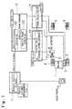
- Fig. 1 is a block diagram of a CVT cruise system to which a shift control system according to the embodiment of the invention is applied.
- a throttle valve 7 of an engine 1 has a vacuum actuator 8 for controlling a valve opening on the basis of an external command, and a throttle opening sensor 9 for detecting a valve opening of the throttle valve 7.
- a left front wheel 3 a right front wheel 4, a left rear wheel 5 and a right rear wheel 6.
- a laser radar 10 is mounted in the front position of a vehicle and outputs radar data for measuring a vehicle distance to a preceding vehicle.
- a vehicle distance measurement control unit 11 measures a vehicle distance to the preceding vehicle on the basis of the radar data from the laser radar 10.
- a CVT cruise control unit 12 serves to run the vehicle at a set vehicle speed while maintaining a vehicle distance to the preceding vehicle in a constant range.
- This CVT cruise control unit 12 includes a vehicle distance controller 121 for calculating a vehicle speed command value on the basis of data on a vehicle distance and a vehicle speed controller 122 for calculating a target driving force on the basis of a vehicle speed command value from the vehicle distance controller 121.
- a throttle control unit 13 controls the vacuum actuator 8 so that a throttle opening corresponding to an engine torque command value can be obtained. And the throttle control unit 13 receives a target driving force from the vehicle speed controller 122 and determines an engine torque command value on the basis of the target driving force, and outputs the engine torque command value to the vacuum actuator 8. In addition, this throttle control unit 13 constitutes a servo system performing a feedback control so that an actual throttle opening of the throttle valve 7 coincides with the engine torque command value.
- a CVT control unit 14 controls a gear ratio of a belt-type continuously variable transmission (CVT) 2 to achieve a target gear ratio.
- the CVT control unit 14 determines a target gear ratio on the basis of a CVT cruise set command from the CVT cruise control unit 12 and outputs a command of achieving the target gear ratio to a hydraulic pressure control valve unit 15 (see Fig. 2) acting as a speed change actuator.
- This CVT control unit 14 constitutes a servo system performing a feedback control so that an actual gear ratio coincides with a target gear ratio.
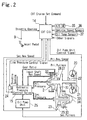
- Fig. 2 is a diagram showing a belt-type continuously variable transmission and a shift control system according to the embodiment.
- a torque converter 20 which includes a lock-up clutch 21 connecting the engine 1 and the belt-type CVT 2 directly.
- the output shaft side of the torque converter 20 is coupled to a transmission input shaft 26.
- One end of this input shaft 26 is provided with primary pulleys 27, 28 of the belt-type CVT 2.
- the belt-type CVT 2 is comprised of the aforementioned primary pulleys 27, 28, secondary pulleys 29, 30 and a belt 31 transmitting torque of the primary pulleys 27, 28 to the secondary pulleys 29, 30.
- a movable primary pulley 28 can be moved in the axial direction of the input shaft 26 by primary hydraulic pressure(pri. pressure) acting on a primary pulley cylinder chamber 32.
- a movable secondary pulley 30 can be moved in the axial direction of an output shaft 34 by secondary hydraulic pressure(sec. pressure) acting on a secondary pulley cylinder chamber 33.
- To the output shaft 34 there is firmly fitted a not-shown drive gear which drives a drive shaft extending to wheels via a pinion mounted on an idler shaft, a final gear and a differential gear unit.
- the control for changing the width of V-shaped pulley grooves of these primary pulleys 27, 28 and secondary pulleys 29, 30 is performed by supplying primary hydraulic pressure and secondary hydraulic pressure, which are produced by the hydraulic pressure control valve unit 15 in accordance with command from the CVT control unit 14, to the primary pulley cylinder chamber 32 and the second pulley cylinder chamber 33 respectively.
- the CVT control unit 14 receives a CVT cruise set command from the CVT cruise control unit 12.
- This CVT control unit 14 receives a throttle opening signal from a throttle opening sensor 9, a switch signal from a kick-down switch 35, a vehicle speed signal from a vehicle speed sensor 36, a transmission oil temperature signal from an oil temperature sensor 37, a primary revolution speed signal from a primary speed sensor 22, a secondary revolution speed signal from a secondary speed sensor 23 and other signals.
- the CVT control unit 14 performs arithmetic processing on the basis of these input signals and outputs a line pressure control signal to a line pressure solenoid 24 and outputs a gear ratio control signal to the hydraulic pressure control valve 15 and outputs an oil pump unit control signal to an oil pump unit 25.
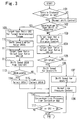
- Fig. 3 is a flow chart showing a shift control in the CVT control unit 14 according to the embodiment.
- step 101 it is determined whether a vehicle distance control is set by the CVT cruise control unit 12. If the result at the step 101 is affirmative, the routine is advanced to step 102. If the result at step 101 is negative, the routine is advanced to a normal shift control in which a target gear ratio is calculated using a target shit map as shown in Fig. 4.
- step 102 it is determined whether deceleration by downshifting is required based on an acceleration/deceleration signal from the vehicle distance controller 121. If the result at the step 102 is affirmative, the routine is advanced to step 109. If the result at the step 102 is negative, the routine is advanced to step 103.
- a target gear ratio GR1 is calculated using a target shit map for a vehicle distance control as shown in Fig. 5.
- the target gear ratio is calculated based on the primary revolution speed (revolution speed of the primary pulleys) obtained from the target shift map.
- step 104 there is calculated a deviation GR1-GR between a target gear ratio GR1 and an actual gear ratio GR.
- step 105 it is determined whether the deviation GR1-GR is equal to or more than 0. If the deviation GR1-GR is equal to or more than 0, it is determined that downshift is required, and the routine is advanced to step 106. If the deviation GR1-GR is less than 0, it is determined that upshift is required, and the routine is advanced to step 107.
- a shift speed is calculated from a shift speed map for downshift.
- a shift speed is calculated from a shift speed map for upshift.
- a normal line pressure control is performed.
- a target gear ratio GR2 corresponding to a target deceleration torque is calculated.
- a shift speed limiter value GR2dL is calculated.
- a deviation GR2-GR between a target gear ratio GR2 and an actual gear ratio GR is calculated.
- a shift speed GR2d is calculated from the shift speed map for downshift.
- step 113 it is determined whether the shift speed limiter value GR2dL is equal to or more than a shift speed GR2d. If the result is GR2dL ⁇ GR2d, the routine is advanced to step 114. If the result is GR2dL ⁇ GR2d, the routine is advanced to step 115.
- GR2d is selected as a shift speed.
- GR2dL is selected as a shift speed.
- a correction line pressure is calculated from a line pressure correction map and added to an ordinary line pressure.
- step 117 it is determined whether a target gear ratio GR1 or GR2 coincides with an actual gear ratio GR. If the result is affirmative, this control is terminated. If the result is negative, the routine returns to the step 116, and the correction line pressure is added.
- a vehicle distance control for maintaining a vehicle distance is started. Then, an acceleration/deceleration is performed depending on a vehicle distance to a preceding vehicle. For example, when the driver runs his own vehicle, maintaining a proper vehicle distance to a preceding vehicle, if another vehicle cuts in between the driver's own vehicle and the preceding vehicle or the preceding vehicle decelerates rapidly, deceleration by downshifting accompanied by engine braking is required.
- deceleration by downshifting is required. If the result is negative, a target gear ratio GR1 is calculated using the shift map for a vehicle distance control as shown in Fig. 5, and a shift speed is calculated based on a deviation from the actual gear ratio GR.
- a deviation GR1-GR between a target gear ratio and an actual gear ratio is less than 0, it is determined that upshift is required because a target gear ratio is low, and a shift speed is calculated using the shift speed map for upshift shown in Fig. 7. In this case, since a gear ratio is changed by decreasing pulley pressure during upshift differently from the time of downshift, the addition of a correction line pressure is not required, and thus an ordinary line pressure control is performed.
- a target gear ratio GR2 corresponding to a target deceleration torque is calculated from a map shown in Fig. 8.
- a shift speed limiter value GR2dL is calculated from a map shown in Fig. 9. The calculation of this speed limiter value GR2dL is made to prevent the occurrence of a problem that a driving wheel may be locked by excessive engine brake when downshift is performed rapidly.
- a shift speed GR2d is calculated from the shift speed map for downshift shown in Fig. 6.
- a shift speed GR2d is smaller than a shift speed limiter value GR2dL when a shift speed limiter value GR2dL is greater than a shift speed GR2d
- the shift speed GR2d is selected.
- the shift speed limiter value GR2dL is selected.
- a correction line pressure is calculated from the line pressure correction map and is added to an ordinary line pressure.
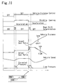
- Fig. 11 is a time chart of the case where a vehicle cuts in between the preceding vehicle and the own vehicle when the vehicle distance control of the embodiment is performed.
- the CVT control unit 14 can change speed with good response, and thereby a vehicle distance can be kept proper.
- a shift speed limiter for setting an upper limit of shift speed when deceleration torque is obtained by shifting a gear ratio to a lower level at the time when a vehicle distance is controlled.
Landscapes
- Engineering & Computer Science (AREA)
- Chemical & Material Sciences (AREA)
- Combustion & Propulsion (AREA)
- Mechanical Engineering (AREA)
- Transportation (AREA)
- General Engineering & Computer Science (AREA)
- Automation & Control Theory (AREA)
- Control Of Transmission Device (AREA)
- Control Of Driving Devices And Active Controlling Of Vehicle (AREA)
- Controls For Constant Speed Travelling (AREA)
- Control Of Vehicle Engines Or Engines For Specific Uses (AREA)
Applications Claiming Priority (2)
| Application Number | Priority Date | Filing Date | Title |
|---|---|---|---|
| JP2000234248A JP3817412B2 (ja) | 2000-08-02 | 2000-08-02 | 無段変速機の変速制御装置 |
| JP2000234248 | 2000-08-02 |
Publications (3)
| Publication Number | Publication Date |
|---|---|
| EP1177934A2 true EP1177934A2 (fr) | 2002-02-06 |
| EP1177934A3 EP1177934A3 (fr) | 2006-10-04 |
| EP1177934B1 EP1177934B1 (fr) | 2011-04-13 |
Family
ID=18726640
Family Applications (1)
| Application Number | Title | Priority Date | Filing Date |
|---|---|---|---|
| EP01118630A Expired - Lifetime EP1177934B1 (fr) | 2000-08-02 | 2001-08-02 | Dispositif de commmande de rapport pour transmission à variation continue |
Country Status (4)
| Country | Link |
|---|---|
| US (1) | US6513610B2 (fr) |
| EP (1) | EP1177934B1 (fr) |
| JP (1) | JP3817412B2 (fr) |
| DE (1) | DE60144414D1 (fr) |
Cited By (3)
| Publication number | Priority date | Publication date | Assignee | Title |
|---|---|---|---|---|
| FR2868362A1 (fr) * | 2004-04-06 | 2005-10-07 | Peugeot Citroen Automobiles Sa | Systeme, procede et support d'enregistrement pour reguler la vitesse d'un vehicule automobile |
| CN103241124A (zh) * | 2013-04-25 | 2013-08-14 | 湖北汽车工业学院 | 一种汽车限档低速控制方法 |
| WO2017137196A1 (fr) * | 2016-02-08 | 2017-08-17 | Agco International Gmbh | Système de transmission à courroie |
Families Citing this family (19)
| Publication number | Priority date | Publication date | Assignee | Title |
|---|---|---|---|---|
| JP2004263737A (ja) * | 2003-02-28 | 2004-09-24 | Jatco Ltd | 無段変速機の変速制御装置 |
| JP4175291B2 (ja) * | 2004-05-12 | 2008-11-05 | トヨタ自動車株式会社 | 車両の減速制御装置 |
| JP4639997B2 (ja) * | 2005-02-18 | 2011-02-23 | トヨタ自動車株式会社 | 車両の減速制御装置 |
| JP4867192B2 (ja) * | 2005-04-14 | 2012-02-01 | 三菱自動車工業株式会社 | 無段変速機の制御装置 |
| JP4434101B2 (ja) * | 2005-08-03 | 2010-03-17 | トヨタ自動車株式会社 | 車両用駆動力制御装置 |
| JP4593486B2 (ja) * | 2006-02-08 | 2010-12-08 | ジヤトコ株式会社 | ベルト式無段変速機の変速制御装置 |
| JP2007237775A (ja) * | 2006-03-06 | 2007-09-20 | Mitsubishi Fuso Truck & Bus Corp | ハイブリッド電気自動車の制御装置 |
| JP4939915B2 (ja) * | 2006-12-21 | 2012-05-30 | 富士重工業株式会社 | 無段変速機の制御装置 |
| JP5045288B2 (ja) * | 2007-07-25 | 2012-10-10 | 井関農機株式会社 | 作業車両 |
| US8554428B2 (en) * | 2007-09-28 | 2013-10-08 | Caterpillar Inc. | CVT control system having variable power source speed |
| CA2774251A1 (fr) * | 2009-09-15 | 2011-03-24 | Consortium De Recherche Brp-Universite De Sherbrooke S.E.N.C. | Procede de commande d'une transmission hydraulique a variation continue |
| JP5199984B2 (ja) * | 2009-11-27 | 2013-05-15 | 本田技研工業株式会社 | 自動変速機のロックアップ制御装置 |
| JP5387911B2 (ja) | 2010-03-12 | 2014-01-15 | スズキ株式会社 | 自動変速機の変速制御装置 |
| CN104334929B (zh) * | 2012-06-08 | 2016-05-04 | 加特可株式会社 | 无级变速器及其油压控制方法 |
| WO2014027065A1 (fr) * | 2012-08-16 | 2014-02-20 | Jaguar Land Rover Limited | Système et procédé de sélection d'un rapport de vitesse de transmission |
| DE102013214308B4 (de) * | 2013-07-22 | 2024-07-11 | Robert Bosch Gmbh | Abstandsregler für Kraftfahrzeuge |
| JP6262052B2 (ja) * | 2014-03-27 | 2018-01-17 | ジヤトコ株式会社 | 無段変速機の制御装置 |
| JP6476867B2 (ja) * | 2015-01-05 | 2019-03-06 | 井関農機株式会社 | 作業車両の変速制御装置 |
| JP7526289B2 (ja) * | 2021-01-14 | 2024-07-31 | ジヤトコ株式会社 | 変速機、変速機の制御方法及びプログラム |
Citations (1)
| Publication number | Priority date | Publication date | Assignee | Title |
|---|---|---|---|---|
| DE19922242A1 (de) | 1998-05-15 | 1999-12-09 | Aisin Aw Co | Fahrzeugsteuerungseinheit |
Family Cites Families (7)
| Publication number | Priority date | Publication date | Assignee | Title |
|---|---|---|---|---|
| JP2848101B2 (ja) * | 1991-04-19 | 1999-01-20 | 三菱自動車工業株式会社 | 内燃機関と連続可変変速機との制御装置 |
| JPH10184877A (ja) * | 1996-12-24 | 1998-07-14 | Toyota Motor Corp | 有段変速機の制御装置 |
| JP3800741B2 (ja) * | 1997-07-04 | 2006-07-26 | 日産自動車株式会社 | 無段変速機の足放しアップシフト変速制御装置 |
| JP3661495B2 (ja) * | 1998-08-26 | 2005-06-15 | 日産自動車株式会社 | 先行車追従制御装置 |
| JP2000318486A (ja) * | 1999-05-14 | 2000-11-21 | Honda Motor Co Ltd | 車両の速度制御装置 |
| US6547692B1 (en) * | 1999-06-12 | 2003-04-15 | Robert Bosch Gmbh | System for adjusting the tension of the continuous belt component of a CVT |
| JP3620359B2 (ja) * | 1999-08-10 | 2005-02-16 | 日産自動車株式会社 | 車両用走行制御装置 |
-
2000
- 2000-08-02 JP JP2000234248A patent/JP3817412B2/ja not_active Expired - Fee Related
-
2001
- 2001-08-02 DE DE60144414T patent/DE60144414D1/de not_active Expired - Lifetime
- 2001-08-02 US US09/921,273 patent/US6513610B2/en not_active Expired - Fee Related
- 2001-08-02 EP EP01118630A patent/EP1177934B1/fr not_active Expired - Lifetime
Patent Citations (1)
| Publication number | Priority date | Publication date | Assignee | Title |
|---|---|---|---|---|
| DE19922242A1 (de) | 1998-05-15 | 1999-12-09 | Aisin Aw Co | Fahrzeugsteuerungseinheit |
Cited By (5)
| Publication number | Priority date | Publication date | Assignee | Title |
|---|---|---|---|---|
| FR2868362A1 (fr) * | 2004-04-06 | 2005-10-07 | Peugeot Citroen Automobiles Sa | Systeme, procede et support d'enregistrement pour reguler la vitesse d'un vehicule automobile |
| CN103241124A (zh) * | 2013-04-25 | 2013-08-14 | 湖北汽车工业学院 | 一种汽车限档低速控制方法 |
| CN103241124B (zh) * | 2013-04-25 | 2015-12-02 | 湖北汽车工业学院 | 一种汽车限档低速控制方法 |
| WO2017137196A1 (fr) * | 2016-02-08 | 2017-08-17 | Agco International Gmbh | Système de transmission à courroie |
| US11221064B2 (en) | 2016-02-08 | 2022-01-11 | Agco International Gmbh | Belt drive transmission system |
Also Published As
| Publication number | Publication date |
|---|---|
| US6513610B2 (en) | 2003-02-04 |
| JP2002048223A (ja) | 2002-02-15 |
| US20020017413A1 (en) | 2002-02-14 |
| EP1177934B1 (fr) | 2011-04-13 |
| DE60144414D1 (de) | 2011-05-26 |
| EP1177934A3 (fr) | 2006-10-04 |
| JP3817412B2 (ja) | 2006-09-06 |
Similar Documents
| Publication | Publication Date | Title |
|---|---|---|
| EP1177934B1 (fr) | Dispositif de commmande de rapport pour transmission à variation continue | |
| EP2372195B1 (fr) | Dispositif de contrôle de commutation de transmission variable continue | |
| US6482122B2 (en) | Driving force control device | |
| US7637843B2 (en) | Control device for a continuously variable transmission and control method thereof | |
| EP0231059B1 (fr) | Système de commande pour un variateur continu de vitesse | |
| US7029410B2 (en) | System for preventing belt slip of belt-type continuously variable transmission | |
| JP2003214533A (ja) | Vベルト式無段変速機のスリップ防止装置 | |
| CN101776141A (zh) | 车辆控制器及控制方法 | |
| JP2003074682A (ja) | 無段変速機の制御装置 | |
| US5178044A (en) | Traction control upon start-up of automobile with continuously variable transmission | |
| US4880094A (en) | Control system for a clutch for a vehicle | |
| US7192372B2 (en) | Hydraulic pressure sensor failure control system for belt-type continuously variable transmission | |
| EP1291559A2 (fr) | Système de commande de changement de vitesse pour transmission automatique | |
| US20070203631A1 (en) | Torque control device for continuously variable transmission | |
| US6485391B2 (en) | Control system for continuously variable automatic transmission | |
| US20210025492A1 (en) | Continuously variable transmission control device and control method | |
| EP0870951B1 (fr) | Dispositif de commande du rapport pour une transmission à variation de vitesse continue | |
| KR100331240B1 (ko) | 무단변속기의변속제어장치 | |
| US20070197323A1 (en) | Hydraulic pressure control device for vehicle continuously variable transmission | |
| JPH1178598A (ja) | 車両用走行制御装置 | |
| JP3505839B2 (ja) | 無段変速機の制御装置 | |
| JPH04181057A (ja) | 車両用変速機の変速制御装置 | |
| JP2002174333A (ja) | ホイール走行式作業車両 | |
| JPH08178000A (ja) | 無段自動変速機の制御装置 | |
| JP2002013623A (ja) | 自動変速機の変速制御装置 |
Legal Events
| Date | Code | Title | Description |
|---|---|---|---|
| PUAI | Public reference made under article 153(3) epc to a published international application that has entered the european phase |
Free format text: ORIGINAL CODE: 0009012 |
|
| 17P | Request for examination filed |
Effective date: 20010802 |
|
| AK | Designated contracting states |
Kind code of ref document: A2 Designated state(s): AT BE CH CY DE DK ES FI FR GB GR IE IT LI LU MC NL PT SE TR |
|
| AX | Request for extension of the european patent |
Free format text: AL;LT;LV;MK;RO;SI |
|
| RAP1 | Party data changed (applicant data changed or rights of an application transferred) |
Owner name: JATCO LTD |
|
| PUAL | Search report despatched |
Free format text: ORIGINAL CODE: 0009013 |
|
| AK | Designated contracting states |
Kind code of ref document: A3 Designated state(s): AT BE CH CY DE DK ES FI FR GB GR IE IT LI LU MC NL PT SE TR |
|
| AX | Request for extension of the european patent |
Extension state: AL LT LV MK RO SI |
|
| AKX | Designation fees paid |
Designated state(s): DE FR GB |
|
| 17Q | First examination report despatched |
Effective date: 20080624 |
|
| RIC1 | Information provided on ipc code assigned before grant |
Ipc: F16H 59/60 20060101AFI20100505BHEP |
|
| GRAP | Despatch of communication of intention to grant a patent |
Free format text: ORIGINAL CODE: EPIDOSNIGR1 |
|
| RIN1 | Information on inventor provided before grant (corrected) |
Inventor name: HINO, AKIRA Inventor name: OCHIAI, TATSUO |
|
| GRAS | Grant fee paid |
Free format text: ORIGINAL CODE: EPIDOSNIGR3 |
|
| GRAA | (expected) grant |
Free format text: ORIGINAL CODE: 0009210 |
|
| AK | Designated contracting states |
Kind code of ref document: B1 Designated state(s): DE FR GB |
|
| REG | Reference to a national code |
Ref country code: GB Ref legal event code: FG4D |
|
| REF | Corresponds to: |
Ref document number: 60144414 Country of ref document: DE Date of ref document: 20110526 Kind code of ref document: P |
|
| REG | Reference to a national code |
Ref country code: DE Ref legal event code: R096 Ref document number: 60144414 Country of ref document: DE Effective date: 20110526 |
|
| PLBE | No opposition filed within time limit |
Free format text: ORIGINAL CODE: 0009261 |
|
| STAA | Information on the status of an ep patent application or granted ep patent |
Free format text: STATUS: NO OPPOSITION FILED WITHIN TIME LIMIT |
|
| 26N | No opposition filed |
Effective date: 20120116 |
|
| GBPC | Gb: european patent ceased through non-payment of renewal fee |
Effective date: 20110802 |
|
| REG | Reference to a national code |
Ref country code: DE Ref legal event code: R097 Ref document number: 60144414 Country of ref document: DE Effective date: 20120116 |
|
| PG25 | Lapsed in a contracting state [announced via postgrant information from national office to epo] |
Ref country code: GB Free format text: LAPSE BECAUSE OF NON-PAYMENT OF DUE FEES Effective date: 20110802 |
|
| PGFP | Annual fee paid to national office [announced via postgrant information from national office to epo] |
Ref country code: DE Payment date: 20130731 Year of fee payment: 13 |
|
| PGFP | Annual fee paid to national office [announced via postgrant information from national office to epo] |
Ref country code: FR Payment date: 20130808 Year of fee payment: 13 |
|
| REG | Reference to a national code |
Ref country code: DE Ref legal event code: R119 Ref document number: 60144414 Country of ref document: DE |
|
| REG | Reference to a national code |
Ref country code: DE Ref legal event code: R119 Ref document number: 60144414 Country of ref document: DE Effective date: 20150303 |
|
| REG | Reference to a national code |
Ref country code: FR Ref legal event code: ST Effective date: 20150430 |
|
| PG25 | Lapsed in a contracting state [announced via postgrant information from national office to epo] |
Ref country code: DE Free format text: LAPSE BECAUSE OF NON-PAYMENT OF DUE FEES Effective date: 20150303 |
|
| PG25 | Lapsed in a contracting state [announced via postgrant information from national office to epo] |
Ref country code: FR Free format text: LAPSE BECAUSE OF NON-PAYMENT OF DUE FEES Effective date: 20140901 |