EP1179460B1 - Dispositif de pédale pour véhicule et automobile équipée de ladite pédale - Google Patents
Dispositif de pédale pour véhicule et automobile équipée de ladite pédale Download PDFInfo
- Publication number
- EP1179460B1 EP1179460B1 EP01118751A EP01118751A EP1179460B1 EP 1179460 B1 EP1179460 B1 EP 1179460B1 EP 01118751 A EP01118751 A EP 01118751A EP 01118751 A EP01118751 A EP 01118751A EP 1179460 B1 EP1179460 B1 EP 1179460B1
- Authority
- EP
- European Patent Office
- Prior art keywords
- pedal
- driver
- force
- footrest
- brake
- Prior art date
- Legal status (The legal status is an assumption and is not a legal conclusion. Google has not performed a legal analysis and makes no representation as to the accuracy of the status listed.)
- Expired - Lifetime
Links
- 238000001514 detection method Methods 0.000 claims description 24
- 230000000994 depressogenic effect Effects 0.000 claims description 11
- 210000002683 foot Anatomy 0.000 description 38
- 210000003423 ankle Anatomy 0.000 description 14
- 238000005452 bending Methods 0.000 description 9
- 230000001133 acceleration Effects 0.000 description 8
- 210000003127 knee Anatomy 0.000 description 5
- 238000012545 processing Methods 0.000 description 5
- 230000005540 biological transmission Effects 0.000 description 4
- 239000000446 fuel Substances 0.000 description 4
- 238000000034 method Methods 0.000 description 3
- 230000003044 adaptive effect Effects 0.000 description 2
- 230000007423 decrease Effects 0.000 description 2
- 238000010586 diagram Methods 0.000 description 2
- 230000003867 tiredness Effects 0.000 description 2
- 208000016255 tiredness Diseases 0.000 description 2
- 238000013459 approach Methods 0.000 description 1
- 238000012937 correction Methods 0.000 description 1
- 230000000881 depressing effect Effects 0.000 description 1
- 238000011161 development Methods 0.000 description 1
- 230000018109 developmental process Effects 0.000 description 1
- 238000002347 injection Methods 0.000 description 1
- 239000007924 injection Substances 0.000 description 1
- 238000009434 installation Methods 0.000 description 1
- 239000007921 spray Substances 0.000 description 1
Images





Classifications
-
- B—PERFORMING OPERATIONS; TRANSPORTING
- B60—VEHICLES IN GENERAL
- B60T—VEHICLE BRAKE CONTROL SYSTEMS OR PARTS THEREOF; BRAKE CONTROL SYSTEMS OR PARTS THEREOF, IN GENERAL; ARRANGEMENT OF BRAKING ELEMENTS ON VEHICLES IN GENERAL; PORTABLE DEVICES FOR PREVENTING UNWANTED MOVEMENT OF VEHICLES; VEHICLE MODIFICATIONS TO FACILITATE COOLING OF BRAKES
- B60T7/00—Brake-action initiating means
- B60T7/02—Brake-action initiating means for personal initiation
- B60T7/04—Brake-action initiating means for personal initiation foot actuated
- B60T7/06—Disposition of pedal
-
- G—PHYSICS
- G05—CONTROLLING; REGULATING
- G05G—CONTROL DEVICES OR SYSTEMS INSOFAR AS CHARACTERISED BY MECHANICAL FEATURES ONLY
- G05G1/00—Controlling members, e.g. knobs or handles; Assemblies or arrangements thereof; Indicating position of controlling members
- G05G1/30—Controlling members actuated by foot
-
- G—PHYSICS
- G05—CONTROLLING; REGULATING
- G05G—CONTROL DEVICES OR SYSTEMS INSOFAR AS CHARACTERISED BY MECHANICAL FEATURES ONLY
- G05G1/00—Controlling members, e.g. knobs or handles; Assemblies or arrangements thereof; Indicating position of controlling members
- G05G1/30—Controlling members actuated by foot
- G05G1/42—Controlling members actuated by foot non-pivoting, e.g. sliding
-
- G—PHYSICS
- G05—CONTROLLING; REGULATING
- G05G—CONTROL DEVICES OR SYSTEMS INSOFAR AS CHARACTERISED BY MECHANICAL FEATURES ONLY
- G05G1/00—Controlling members, e.g. knobs or handles; Assemblies or arrangements thereof; Indicating position of controlling members
- G05G1/30—Controlling members actuated by foot
- G05G1/48—Non-slip pedal treads; Pedal extensions or attachments characterised by mechanical features only
- G05G1/487—Pedal extensions
-
- G—PHYSICS
- G05—CONTROLLING; REGULATING
- G05G—CONTROL DEVICES OR SYSTEMS INSOFAR AS CHARACTERISED BY MECHANICAL FEATURES ONLY
- G05G1/00—Controlling members, e.g. knobs or handles; Assemblies or arrangements thereof; Indicating position of controlling members
- G05G1/58—Rests or guides for relevant parts of the operator's body
- G05G1/60—Foot rests or foot guides
-
- G—PHYSICS
- G05—CONTROLLING; REGULATING
- G05G—CONTROL DEVICES OR SYSTEMS INSOFAR AS CHARACTERISED BY MECHANICAL FEATURES ONLY
- G05G5/00—Means for preventing, limiting or returning the movements of parts of a control mechanism, e.g. locking controlling member
- G05G5/03—Means for enhancing the operator's awareness of arrival of the controlling member at a command or datum position; Providing feel, e.g. means for creating a counterforce
-
- Y—GENERAL TAGGING OF NEW TECHNOLOGICAL DEVELOPMENTS; GENERAL TAGGING OF CROSS-SECTIONAL TECHNOLOGIES SPANNING OVER SEVERAL SECTIONS OF THE IPC; TECHNICAL SUBJECTS COVERED BY FORMER USPC CROSS-REFERENCE ART COLLECTIONS [XRACs] AND DIGESTS
- Y10—TECHNICAL SUBJECTS COVERED BY FORMER USPC
- Y10T—TECHNICAL SUBJECTS COVERED BY FORMER US CLASSIFICATION
- Y10T74/00—Machine element or mechanism
- Y10T74/20—Control lever and linkage systems
- Y10T74/20528—Foot operated
-
- Y—GENERAL TAGGING OF NEW TECHNOLOGICAL DEVELOPMENTS; GENERAL TAGGING OF CROSS-SECTIONAL TECHNOLOGIES SPANNING OVER SEVERAL SECTIONS OF THE IPC; TECHNICAL SUBJECTS COVERED BY FORMER USPC CROSS-REFERENCE ART COLLECTIONS [XRACs] AND DIGESTS
- Y10—TECHNICAL SUBJECTS COVERED BY FORMER USPC
- Y10T—TECHNICAL SUBJECTS COVERED BY FORMER US CLASSIFICATION
- Y10T74/00—Machine element or mechanism
- Y10T74/20—Control lever and linkage systems
- Y10T74/20528—Foot operated
- Y10T74/2054—Signal
-
- Y—GENERAL TAGGING OF NEW TECHNOLOGICAL DEVELOPMENTS; GENERAL TAGGING OF CROSS-SECTIONAL TECHNOLOGIES SPANNING OVER SEVERAL SECTIONS OF THE IPC; TECHNICAL SUBJECTS COVERED BY FORMER USPC CROSS-REFERENCE ART COLLECTIONS [XRACs] AND DIGESTS
- Y10—TECHNICAL SUBJECTS COVERED BY FORMER USPC
- Y10T—TECHNICAL SUBJECTS COVERED BY FORMER US CLASSIFICATION
- Y10T74/00—Machine element or mechanism
- Y10T74/20—Control lever and linkage systems
- Y10T74/20576—Elements
- Y10T74/20888—Pedals
-
- Y—GENERAL TAGGING OF NEW TECHNOLOGICAL DEVELOPMENTS; GENERAL TAGGING OF CROSS-SECTIONAL TECHNOLOGIES SPANNING OVER SEVERAL SECTIONS OF THE IPC; TECHNICAL SUBJECTS COVERED BY FORMER USPC CROSS-REFERENCE ART COLLECTIONS [XRACs] AND DIGESTS
- Y10—TECHNICAL SUBJECTS COVERED BY FORMER USPC
- Y10T—TECHNICAL SUBJECTS COVERED BY FORMER US CLASSIFICATION
- Y10T74/00—Machine element or mechanism
- Y10T74/20—Control lever and linkage systems
- Y10T74/20576—Elements
- Y10T74/20918—Foot rests
Definitions
- the present invention relates to a pedal device for a vehicle and an automobile using the same, particularly to a pedal device of a vehicle suitable for the use in the vehicle having an automatic cruise control where the driver does not need the accelerator operation and an automobile using the same.
- a self-control system in which the speed of automobile can be controlled to become a preset speed of automobile, for example, like following distance control automatic cruise (ACC: Adaptive Cruise Control), and an engine, a motor, a transmission, and a brake is self-controlled so as to keep the safe following distance by detecting the distance between this car and the preceding car with radar.
- ACC Adaptive Cruise Control
- an engine, a motor, a transmission, and a brake is self-controlled so as to keep the safe following distance by detecting the distance between this car and the preceding car with radar.
- ACC Adaptive Cruise Control
- an engine, a motor, a transmission, and a brake is self-controlled so as to keep the safe following distance by detecting the distance between this car and the preceding car with radar.
- ACC Adaptive Cruise Control
- the stop and deceleration are controlled based on driver's will to improve safety more.
- the deceleration and the stop are controlled by operating only brake pedal of a present braking system, and the
- the start and stop of a vehicle is carried out by one pedal running, in which only brake operation is performed when set in a slow acceleration running mode under the traffic jam.
- a brake pedal device has the footrest function to put the foot on in usual and to work the brake by stepping on the brake pedal harder than usually.
- brake pedal used in the method previously proposed is one being used in general, brake operation is performed around the heel put on the floor face. Therefore, a first problem is that it is impossible to depress strongly the brake pedal when the rapid braking is required.
- the US-452,606 relates to improvements in the means of actuation of control levers of automobiles relating to the actuation of foot-controlled brakes and throttle levers, wherein a footplate and a foot rest are shown on which the driver's foot can be placed.
- the EP 0 909 687 A1 relates to a vehicle brake system including a brake pedal having a proximity sensor sending a signal to a control unit as soon as the driver's foot approaches the brake pedal.
- the brake pedal can be strongly depressed when the rapid braking also is required compared with brake operation in which the brake operation is performed around the heel put on the floor face, because brake pedal can be depressed by the bending and stretching movement.
- the impact on the driver at a moment shifted from the state of footrest to the state of brake operation can be reduced, and the rapid braking which the driver does not intend can be prevented.
- the flexibility can be given to the bending angle of driver's ankle, and the tiredness of the driver can be reduced.
- the pedal device can further include:
- footrest force calculation means calculates the footrest force from the driver's force-on-pedal of the driver detected by the force-on-pedal detection means and foot load detected by the foot load detection means, and adjusts suitable footrest force for an individual driver automatically.
- the work load to the driver is reduced under the condition that the driver must put the foot on brake pedal for a long time such as the running on the downward slope when jamming, the running by the creep when jamming, and the state of footrest to put the foot on brake pedal while operating the automatic running device.
- Brake pedal unit 10 includes pedal member 11, arm member 12, footrest means 13, brake rod 14, detection means 15, footrest force calculation means 16, and buffer means 17.
- Pedal member 11 is composed of footplate member 11a on which driver D applies the force-on-pedal and protruding portion 11b which is a heel putting part for driver D to put the heel.
- Arm member 12 is composed of arm part 12a, and stopper 12b to restrict the movement of the pedal member 11.
- the pedal member 11 is supported rotatably with arm member 12 by axis AX1.
- the angle of pedal member 11 changes according to the bending angle of driver D's ankle.
- Arm member 12 is supported rotatably with brake bracket Bb by axis AX2.
- Pedal member 11 does not move even if the driver naturally puts the foot on pedal member 11 because movable element 13c is connected or integrated with arm member 12 , and thus the brake is never depressed. That is, pedal member 11 has the function of the footrest.
- movable element 13c becomes movable.
- pedal member 11 is depressed under such a condition, the movement is transmitted to brake booster BB through arm member 12 and brake rod 14.
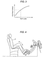
- Footrest force calculation means 16 calculates the amount of the energizing of coil 13a, in order to obtain the necessary footrest force for driver D's footrest from the relation between the output of force-on-pedal detection means 15a and the footrest force as shown in Fig.2 and the relation between the output of foot load detection means 15b and the footrest force as shown in Fig.3. Further, driver's braking-will is perceived when the force-on-pedal becomes more than the predetermined value, and the energizing to coil 13a is intercepted.
- the angle of pedal member 11 can change according to the bending angle of driver D's ankle. Therefore, because it is possible to depress the pedal with pushing the heel out at brake operation while reducing the load at footrest to driver D, compared with the one that its angle is fixed, it is possible to depress the pedal strongly without forcing an excessive load on the ankle.
- a conventional stroke can be secured because brake pedal is maintained in the initial position when using the brake pedal as a footrest, and a slight adjustment of braking force is easy.
- buffer means 17 is composed of the motor with rotation axis on the same axis as axis AX2 on which brake pedal bracket Bb installed in body B of the vehicle and arm member 12 are mounted.
- the motor which is buffer means 17 is energized, and the motor is rotated, the torque to resist the movement of arm 12 in a turning direction (the direction of arrow A in figure).
- buffer means 17 is explained with reference to Fig.5.
- Fig.5 is an explanatory view of the operation of the buffer means in the pedal device of the vehicle according to the first embodiment of the present invention.
- the ordinate of Fig.5 (A) shows driver's force-on-pedal. Further, the ordinate of Fig.5 (B) shows the amount of energizing to buffer means 17.
- Fig.5 (C) shows the amount of energizing to footrest means 13 of the solenoid type.
- the abscissa of each figure shows time.
- footrest force calculation means 16 calculates the necessary footrest force based on the foot load and the force-on-pedal shown in Figs.2 and 3, and energizes footrest means 13 for generating this footrest, as shown in Fig.5 (C). Further, buffer means 17 is not energized at this time, as shown in Fig.5 (B).
- the force-on-pedal increases as shown in Fig.5 (A) when the brake is depressed so that the driver may brake at time T0.
- footrest force calculation means 16 gradually decreases the amount of energizing to footrest means 13 as shown in Fig.5 (C), and gradually increases the amount of energizing to buffer means 17 as shown in Fig.5 (B).
- the torque of the motor which is buffer means 17 is generated so as to resist the movement of arm member 12 in a turning direction of arrow A.
- footrest force calculation means 16 gradually decreases the amount of energizing to buffer means 17 as shown in Fig.5 (B) when the amount of energizing to footrest means 13 becomes 0 at time T1 as shown in Fig.5 (C).
- the force-on-pedal increases gradually according to the depressing of pedal member 11 by driver's braking operation as shown in Fig.5 (A) by solid line X.
- the sense of discomfort of brake operation caused by the driver can be canceled by using the buffer means, and the operability of the brake can be improved. Further, the rapid braking when the energizing to the footrest means is intercepted can be prevented, and the safety can be improved.
- Fig.6 is a configuration view showing another configuration of the buffer means used in the pedal device of the vehicle according to the first embodiment of the present invention.
- Fig.6 shows only the main part of Fig.1. Further, the same sign as Fig.1 designates the same part.
- brake member is provided with protruding portion for driver D to put the heel, driver D can put the foot on pedal member in the state of footrest. Therefore, because driver D can brake by operation in which the driver's knee is extended, when braking, it is possible to do stronger breaking. Especially, braking distance can be shortened in the emergency, and the safety improves.
- footrest means 13 maintains arm member 12 in the initial position.
- arm member 12 is released from the restriction of footrest means 13.
- footplate member 11a moves according to the manipulated variable when driver D applies the force-on-pedal on the pedal member 11A, and working with footplate member 11a, slide member 11c moves on the floor face.
- footrest means 13 When the force-on-pedal is less than fixed value, footrest means 13 according to this embodiment maintains arm member 12 in the initial position. When more than the force-on-pedal corresponding to a fixed position is applied, arm member 12 is released from the restriction of footrest means 13, and arm member 12 becomes possible to move according to driver D's force-on-pedal. As a result, usual brake operation becomes possible. Therefore, brake pedal can be used as footrest when driver D puts the foot on brake pedal with the force-on-pedal below a fixed value by footrest means 13, and it is possible to do continuously brake operation without changing the pedal to be stepped. As a result, the characteristic of the footrest is improved.
- the sense of discomfort of brake operation caused by the driver can be canceled by using the buffer means, and the operability of the brake can be improved.
- the rapid braking when the energizing to the footrest means is intercepted can be prevented, and the safety can be improved.
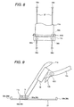
- Fig.8 is a plan view showing the configuration of the pedal member used for the pedal device of the vehicle according to the second embodiment of the present invention. Further, Fig.9 is side elevation of Fig.8. In Fig.8, the same sign as Fig.7 shows the same part.
- Slide member 11c is provided with rotatable support wheels 36a and 36b. Further, wheel 35a and 35b are provided in axis AX3. On the other hand, rail member 37, and wheel stoppers 38a, 38b, 38c and 38d are mounted on the floor face.
- Fig.10 is a side elevation showing another configuration of the pedal member used for the pedal device of the vehicle according to the second embodiment of the present invention.
- the same sign as Fig.8 designates the same part.
- This example has supplementary wheel 42 in addition to the configuration shown in Fig.8.
- Rail 37 is sandwiched between wheel 35 and support wheel 36, and supplementary wheel 42, and thus the wheels can be prevented to run off. Further, the height of rail 37 is equalized to the height of the floor face by providing the concave part on floor face F and arranging rail 38 in this concave part. As a result, there is no obstacle in the drive of the driver.
- brake pedal can be used as footrest, and it is possible to do continuously brake operation without changing the pedal to be stepped. As a result, the characteristic of the footrest is improved.
- brake member is provided with protruding portion for driver D to put the heel, driver D can put the foot on pedal member in the state of footrest.
- driver D can brake by operation in which the driver's knee is extended, when braking, it is possible to do stronger breaking. Especially, braking distance can be shortened in the emergency, and the safety improves.
- the angle of pedal member can change according to the bending angle of driver D's ankle.
- the sense of discomfort of brake operation caused by the driver can be canceled by using the buffer means, and the operability of the brake can be improved.
- the rapid braking when the energizing to the footrest means is intercepted can be prevented, and the safety can be improved.
- Fig.11 is a side elevation showing the configuration of the pedal member used for the pedal device of the vehicle according to the third embodiment of the present invention.
- Fig.12 is a plan view of the configuration shown in Fig.11. In Figs.11 and 12, the same sign as Figs.7 and 8 designates the same part.
- Roller support members 40a, 40b, 40c and 40d to support rollers 39a, 39b, and belt member 41 are provided on the floor face.
- Slide member 11c is fixed to a part of belt member 41. Slide member 11c smoothly moves on the floor face because belt member 41 operates with the movement of slide member 11c.
- Fig.13 is a side elevation showing another configuration of the pedal member used for the pedal device of the vehicle according to the third embodiment of the present invention.
- the same sign as Fig.11 designates the same part.
- the height of belt member 41 is equalized to the height of the floor face by providing the concave part on floor face F and arranging belt member 41 in this concave part. As a result, there is no obstacle in the drive of the driver.
- the angle of pedal member can change according to the bending angle of driver D's ankle. Therefore, because it is possible to depress the pedal with pushing the heel out at brake operation while reducing the load at footrest to driver D, it is possible to depress the pedal strongly without forcing an excessive load on the ankle.
- Fig.14 is a side elevation showing the configuration of the pedal member used for the pedal device of the vehicle according to the fourth embodiment of the present invention.
- Fig.14 the same sign as Fig.9 designates the same part.
- Pedal member 11 is composed of footplate member 11a on which driver D applies the force-on-pedal and protruding member 11d on which driver D puts the heel and which is slidable on the floor face.
- Protruding member 11d is provided with rotatable support wheels 44a and 44b, and can slide on the floor face in a direction of arrow C.
- Protruding portion member 11d is fixed to footplate 11a.
- pedal member 11B can slide along guide member 18 mounted on arm member 12 in a direction of arrow B.
- Guide member 18 is supported rotatably to arm member 12 by axis AX1.
- the angle of pedal member can change according to the bending angle of driver D's ankle. Therefore, because it is possible to depress the pedal with pushing the heel out at brake operation while reducing the load at footrest to driver D, it is possible to depress the pedal strongly without forcing an excessive load on the ankle.
- the sense of discomfort of brake operation caused by the driver can be canceled by using the buffer means, and the operability of the brake can be improved. Further, the rapid braking when the energizing to the footrest means is intercepted can be prevented, and the safety can be improved.
- Fig.15 is a block diagram showing the configuration of the vehicle equipped with the pedal device of the vehicle according to another embodiment of the present invention.
- Fig.16 is a flow chart showing the operation mode of the automobile according to this embodiment. The same sign as Fig.1 designates the same part in these figures.
- Pedal device 10 including solenoid type footrest means 13 and buffer means 17, engine 3, and transmission 5 including motor 4, for braking drive system 8 having brake device 6a, ⁇ , 6d and tire 7a, ⁇ , 7d, and control system 9 for controlling braking drive system 8 according to input information are installed in automobile 100.
- Motor 4 is driven by the electric power supplied from battery 25.
- Control system 9 communicates through the network among engine , transmission 5, control unit (not shown) for controlling the brake device 6, control unit (not shown) for managing the whole braking drive system 8, and footrest force calculation means 16 for controlling footrest means 13 and buffer means 17.
- control system 9 inputs information on detection means 15, information on running mode set switch 25 and driving force (acceleration) set switch 26, information ⁇ from the sensor of the manipulated variable of the accelerator pedal, information Nfr from right front wheel rotation sensors, information Nfl from left front wheel rotation sensors, information Nrr from right rear wheel rotation sensors, information Nrl from left front wheel rotation sensors, engine revolution speed information Ne, motor revolution speed information Nm,
- the distance S between the automobile and the previous automobile and relative velocity Vr of the automobile to the previous automobile obtained from the radar system (not shown), etc., and signals from speed set switches 28 by which the driver can voluntarily set the speed of the target and footrest force correction switches 29, etc.
- Control system 9 controls Engine 3, transmission 5, and brake device 6 on the basis of these input signals, and thus the acceleration, the deceleration, the start, the stop and the fixed velocity running of the vehicle are executed.
- the footrest force is presumed by control system 9 including footrest force calculation means 16 based on the information from detection means 15 at this time, and reflected to the amount of the energizing of solenoid type footrest means 13 and buffer means 17.
- the operation of footrest means 13 can be turned on or turned off by the footrest button of running mode set switch 25.
- the engine includes electronically controlled throttle 22 for controlling the amount of intake air, fuel injection valve 23 for supplying the amount of the fuel which corresponds to the intake air to obtain the target air/fuel ratio, and ignition plugs for ignite the fuel spray.
- control system 9 judges whether it is in one pedal ACC mode.
- the ACC Adaptive Cruise Control or following distance automatic cruise control
- the processing advances to step s20, otherwise, the control in this embodiment is ended.
- Control system 9 judges the presence of driver's braking-will in step s20.
- the presence of the braking-will is judged by footrest force calculation means 16, based on the driver's force-on-pedal and/or foot load which are the output of detection means 15. If the driver has the braking-will, the processing advances to step s30, otherwise, the processing advances to step s40.
- the control system 9 judges the presence of the preceding automobile in step s40, based on relative velocity Vr of the automobile to the preceding automobile and the distance S between two automobiles obtained from the radar system etc. If there is a preceding automobile, the processing advances to step s50, and otherwise, the processing advances to step s60.
- Control system 9 carries out the follow acceleration in step s50 according to the distance between two automobiles when there is a preceding automobile.
- control system 9 accelerates in step s60 according to driver's set speed of automobile when there is no preceding automobile.
- the driver can control the deceleration and acceleration of the vehicle only by the brake operation without replacing the foot to step the accelerator pedal in the one pedal ACC mode.
- the tiredness under the drive is reduced.
Landscapes
- Engineering & Computer Science (AREA)
- Physics & Mathematics (AREA)
- General Physics & Mathematics (AREA)
- Automation & Control Theory (AREA)
- Transportation (AREA)
- Mechanical Engineering (AREA)
- Braking Elements And Transmission Devices (AREA)
- Arrangement And Mounting Of Devices That Control Transmission Of Motive Force (AREA)
- Mechanical Control Devices (AREA)
Claims (7)
- Un dispositif de pédale pour véhicule possédant une pédale (11) enfoncée par le conducteur D et un bras (12) engagé avec la pédale (11) permettant le pivotement lorsque la pédale (11) est enfoncée et permettant de transmettre la force appliquée sur la pédale par le conducteur au maítre-cylindre de frein, comprenant également :dans lequel ladite pédale (11) inclut une plaque d'appui pour le pied (11a) devant être enfoncée par le conducteur D et une partie en saillie (11b) engagée avec la plaque d'appui (11a), sur laquelle le talon du conducteur peut être posé, caractérisé parun moyen de réduction (13) permettant de réduire le pivotement du bras (12) lorsque la force appliquée sur la pédale par le conducteur qui agit sur la pédale (11) est inférieure à la valeur fixée, et
un moyen de butée (17) permettant de générer un couple pour résister au pivotement dudit bras (12) lorsque ladite pédale (11) est enfoncée,
dans lequel un moyen de calcul de la force de repose-pied (16) est fourni pour contrôler ledit moyen de butée (17) lors de la suspension de la réduction du pivotement dudit bras (12) imposée par ledit moyen de réduction (13), de manière à ajuster la force appliquée sur ladite pédale (11). - Le dispositif de pédale pour un véhicule selon la revendication 1, dans lequel ladite partie adaptée pour poser le talon est une partie en saillie (11b) fixée en bas de ladite plaque d'appui pour le pied (11a).
- Le dispositif de pédale pour un véhicule selon la revendication 1, dans lequel ladite partie adaptée pour poser le talon est une partie coulissante soutenue de manière à pouvoir pivoter en bas de ladite plaque d'appui (11a), qui peut coulisser sur le plancher du véhicule.
- Le dispositif de pédale pour un véhicule selon la revendication 1, dans lequel ladite pédale (11) est soutenue de manière à pouvoir pivoter par rapport audit bras (12) et ledit bras (12) possède la pièce d'arrêt (12b) qui limite le mouvement de ladite pédale (11).
- Le dispositif de pédale pour un véhicule selon la revendication 1, comprenant également :un moyen de détection de la force appliquée sur la pédale (15a) disposé dans ladite plaque d'appui pour le pied (11a), permettant de détecter la force appliquée sur la pédale par le conducteur,un moyen de détection de la charge au pied (15b) disposé sur ladite partie adaptée pour poser le talon, permettant de détecter ladite charge au pied du conducteur, etun moyen de calcul de la force de repose-pied (16) permettant de contrôler ledit dispositif de réduction en se basant sur au moins un résultat dudit moyen de détection de la charge au pied (15b) et dudit dispositif de détection de la force appliquée sur la pédale (15a).
- Le dispositif de pédale pour véhicule selon la revendication 5, dans lequel ledit dispositif de calcul de la force de repose-pied (16) calcule la force de repose-pied à partir de la force appliquée sur la pédale par le conducteur D détectée par ledit dispositif de détection de la force appliquée sur la pédale (15a) et à partir de la charge au pied détectée par ledit dispositif de détection de la charge au pied (15b) et ajuste automatiquement la force de repose-pied appropriée pour un conducteur individuel D.
- Une automobile utilisant le dispositif de pédale selon au moins l'une des revendications 1 à 6.
Applications Claiming Priority (2)
| Application Number | Priority Date | Filing Date | Title |
|---|---|---|---|
| JP2000241625A JP2002053018A (ja) | 2000-08-09 | 2000-08-09 | 車両のペダル装置及びそれを用いた自動車 |
| JP2000241625 | 2000-08-09 |
Publications (3)
| Publication Number | Publication Date |
|---|---|
| EP1179460A2 EP1179460A2 (fr) | 2002-02-13 |
| EP1179460A3 EP1179460A3 (fr) | 2003-11-26 |
| EP1179460B1 true EP1179460B1 (fr) | 2005-10-26 |
Family
ID=18732788
Family Applications (1)
| Application Number | Title | Priority Date | Filing Date |
|---|---|---|---|
| EP01118751A Expired - Lifetime EP1179460B1 (fr) | 2000-08-09 | 2001-08-07 | Dispositif de pédale pour véhicule et automobile équipée de ladite pédale |
Country Status (4)
| Country | Link |
|---|---|
| US (2) | US6883398B2 (fr) |
| EP (1) | EP1179460B1 (fr) |
| JP (1) | JP2002053018A (fr) |
| DE (1) | DE60114320T2 (fr) |
Families Citing this family (19)
| Publication number | Priority date | Publication date | Assignee | Title |
|---|---|---|---|---|
| JP4173324B2 (ja) * | 2002-06-20 | 2008-10-29 | 日産自動車株式会社 | アクセルペダル装置 |
| JP4039184B2 (ja) * | 2002-08-29 | 2008-01-30 | 株式会社アドヴィックス | クリープ走行制御装置 |
| DE102006007664A1 (de) * | 2006-02-18 | 2007-08-23 | Bayerische Motoren Werke Ag | Fahrpedalsystem |
| DE102006053408A1 (de) * | 2006-11-13 | 2008-05-29 | Siemens Ag | Pedal für ein Fahrzeug |
| FR2920053B1 (fr) * | 2007-08-17 | 2015-10-09 | Alain Boulas | Dispositif d'aide a l'actionnement du pedalier d'un vehicule automobile |
| WO2010020713A1 (fr) * | 2008-08-19 | 2010-02-25 | Alain Boulas | Dispositif d'aide a l'actionnement du pedalier d'un vehicule automobile |
| US20120042744A1 (en) * | 2010-08-18 | 2012-02-23 | Sang Hoon Han | Organ type acceleration pedal assembly employing linear bearing |
| KR101316439B1 (ko) * | 2010-11-30 | 2013-10-08 | 주식회사 동희산업 | 펜턴트형 조정식 오르간 엑셀 페달장치 |
| KR101398502B1 (ko) * | 2012-08-17 | 2014-06-27 | 박옥남 | 차량용 가속페달 |
| JP5708675B2 (ja) * | 2013-01-24 | 2015-04-30 | トヨタ自動車株式会社 | 車両制御装置 |
| US9261894B2 (en) * | 2013-03-08 | 2016-02-16 | Woodward, Inc. | Multiple degrees of translational adjustment pedals |
| KR101545661B1 (ko) | 2013-08-09 | 2015-08-20 | 박옥남 | 차량용 가속 페달 |
| US20160004271A1 (en) * | 2014-07-01 | 2016-01-07 | Raytheon BBN Technologies, Corp. | Accelerator Pedal Assembly |
| DE102014214786B4 (de) * | 2014-07-28 | 2019-03-14 | Volkswagen Aktiengesellschaft | Verfahren zum Verstellen wenigstens eines Pedals einer Kraftfahrzeug-Pedalerie sowie Vorrichtung dafür |
| US9552011B2 (en) * | 2014-10-30 | 2017-01-24 | Mikal Wersland | System for modifying throttle control for UTV's and related vehicles |
| GB2551575A (en) * | 2016-06-24 | 2017-12-27 | Bentley Motors Ltd | Virtual footrest apparatus |
| GB2584395A (en) * | 2019-05-02 | 2020-12-09 | Bentley Motors Ltd | Adjustable throttle pedal assembly |
| US11396362B2 (en) | 2019-11-01 | 2022-07-26 | Woodward, Inc. | Rudder and brake pedal assembly |
| DE102020213465A1 (de) | 2020-10-26 | 2022-04-28 | Volkswagen Aktiengesellschaft | Bremsbetätigungseinrichtung |
Family Cites Families (12)
| Publication number | Priority date | Publication date | Assignee | Title |
|---|---|---|---|---|
| US1120460A (en) * | 1913-08-13 | 1914-12-08 | Rosa Kaufman | Foot-rest attachment for automobile controlling-levers. |
| US1403443A (en) * | 1920-05-03 | 1922-01-10 | John L Paul | Accelerator safety pedal control |
| US1516862A (en) * | 1923-10-18 | 1924-11-25 | William J Loury | Foot-pedal rest |
| US1613237A (en) * | 1925-04-18 | 1927-01-04 | Harry A Elflain | Foot rest for motor vehicles |
| GB452606A (en) * | 1934-06-21 | 1936-08-26 | William Arkley | Improvements relating to control levers of automobiles |
| US2464327A (en) * | 1943-09-09 | 1949-03-15 | Harley C Mack | Vehicle brake system |
| US3426615A (en) * | 1967-05-29 | 1969-02-11 | Raymond C Strauss | Vehicle driving controls |
| US4802381A (en) * | 1987-03-18 | 1989-02-07 | Lo Nsin Hsin | Compound acceleration-brake pedal assembly |
| JPH0438600A (ja) | 1990-06-04 | 1992-02-07 | Mitsubishi Electric Corp | 車両の走行制御装置 |
| JP3980673B2 (ja) * | 1995-10-30 | 2007-09-26 | 本田技研工業株式会社 | 車両におけるブレーキ装置 |
| GB9721723D0 (en) * | 1997-10-15 | 1997-12-10 | Rover Group | Vehicle brake systems |
| EP1792799A3 (fr) * | 1999-07-01 | 2008-10-22 | Hitachi, Ltd. | Appareil pour régler le freinage et l'effort tractif dans un véhicule |
-
2000
- 2000-08-09 JP JP2000241625A patent/JP2002053018A/ja active Pending
-
2001
- 2001-08-07 EP EP01118751A patent/EP1179460B1/fr not_active Expired - Lifetime
- 2001-08-07 US US09/922,917 patent/US6883398B2/en not_active Expired - Fee Related
- 2001-08-07 DE DE60114320T patent/DE60114320T2/de not_active Expired - Fee Related
-
2004
- 2004-08-11 US US10/915,572 patent/US20050005728A1/en not_active Abandoned
Also Published As
| Publication number | Publication date |
|---|---|
| DE60114320T2 (de) | 2006-07-13 |
| US20050005728A1 (en) | 2005-01-13 |
| DE60114320D1 (de) | 2005-12-01 |
| US6883398B2 (en) | 2005-04-26 |
| EP1179460A2 (fr) | 2002-02-13 |
| JP2002053018A (ja) | 2002-02-19 |
| US20020020247A1 (en) | 2002-02-21 |
| EP1179460A3 (fr) | 2003-11-26 |
Similar Documents
| Publication | Publication Date | Title |
|---|---|---|
| EP1179460B1 (fr) | Dispositif de pédale pour véhicule et automobile équipée de ladite pédale | |
| JP3666342B2 (ja) | 走行制御装置 | |
| JP3943046B2 (ja) | 車両の走行制御装置 | |
| EP2318229B1 (fr) | Réaction d'accélérateur pour appareil de commande | |
| US6724300B2 (en) | Alarm device and running control apparatus including the alarm device | |
| US6554744B2 (en) | Apparatus and method of controlling the road speed of a motor vehicle | |
| US6502908B1 (en) | Control system for a vehicle | |
| US20040099085A1 (en) | Accelerator pedal with braking action | |
| EP1344672B1 (fr) | Système de régulation des espacements | |
| AU7045500A (en) | Method and device for assisting a driver of a vehicle | |
| US20050167175A1 (en) | Cruise control system | |
| EP1707425B1 (fr) | Système de pédale | |
| US20060284481A1 (en) | Brake pedal control apparatus | |
| CN112537199B (zh) | 车辆用踏板装置 | |
| JP4660393B2 (ja) | 車両のクルーズコントロール装置 | |
| JP3572448B2 (ja) | 車両用制動制御装置 | |
| JPH0946808A (ja) | 自動変速機搭載車用リターダ装置 | |
| EP4082857B1 (fr) | Procédé de commande de force d'entraînement et dispositif de commande de force d'entraînement | |
| JP2019202647A (ja) | 自動運転制御装置 | |
| JP2000006682A (ja) | 定速走行装置 | |
| EP1336526A2 (fr) | Procedé, système et régulateur pour la régulation de la vitesse d'un véhicule et de la distance entre deux véhicules | |
| JP2008217331A (ja) | ペダル装置及び制動力制御装置 | |
| JPH11314541A (ja) | 自動ブレーキ装置 | |
| JP2002308076A (ja) | 自動制動制御装置におけるブレーキペダルの操作検知装置 | |
| JPH07164914A (ja) | 車両駆動出力制御装置 |
Legal Events
| Date | Code | Title | Description |
|---|---|---|---|
| PUAI | Public reference made under article 153(3) epc to a published international application that has entered the european phase |
Free format text: ORIGINAL CODE: 0009012 |
|
| AK | Designated contracting states |
Kind code of ref document: A2 Designated state(s): AT BE CH CY DE DK ES FI FR GB GR IE IT LI LU MC NL PT SE TR |
|
| AX | Request for extension of the european patent |
Free format text: AL;LT;LV;MK;RO;SI |
|
| PUAL | Search report despatched |
Free format text: ORIGINAL CODE: 0009013 |
|
| AK | Designated contracting states |
Kind code of ref document: A3 Designated state(s): AT BE CH CY DE DK ES FI FR GB GR IE IT LI LU MC NL PT SE TR |
|
| AX | Request for extension of the european patent |
Extension state: AL LT LV MK RO SI |
|
| 17P | Request for examination filed |
Effective date: 20040316 |
|
| 17Q | First examination report despatched |
Effective date: 20040422 |
|
| AKX | Designation fees paid |
Designated state(s): DE FR GB IT |
|
| GRAP | Despatch of communication of intention to grant a patent |
Free format text: ORIGINAL CODE: EPIDOSNIGR1 |
|
| GRAS | Grant fee paid |
Free format text: ORIGINAL CODE: EPIDOSNIGR3 |
|
| RAP1 | Party data changed (applicant data changed or rights of an application transferred) |
Owner name: HITACHI, LTD. |
|
| GRAA | (expected) grant |
Free format text: ORIGINAL CODE: 0009210 |
|
| AK | Designated contracting states |
Kind code of ref document: B1 Designated state(s): DE FR GB IT |
|
| REG | Reference to a national code |
Ref country code: GB Ref legal event code: FG4D |
|
| REF | Corresponds to: |
Ref document number: 60114320 Country of ref document: DE Date of ref document: 20051201 Kind code of ref document: P |
|
| ET | Fr: translation filed | ||
| PLBE | No opposition filed within time limit |
Free format text: ORIGINAL CODE: 0009261 |
|
| STAA | Information on the status of an ep patent application or granted ep patent |
Free format text: STATUS: NO OPPOSITION FILED WITHIN TIME LIMIT |
|
| 26N | No opposition filed |
Effective date: 20060727 |
|
| PGFP | Annual fee paid to national office [announced via postgrant information from national office to epo] |
Ref country code: DE Payment date: 20080908 Year of fee payment: 8 |
|
| PGFP | Annual fee paid to national office [announced via postgrant information from national office to epo] |
Ref country code: FR Payment date: 20080723 Year of fee payment: 8 Ref country code: IT Payment date: 20080716 Year of fee payment: 8 |
|
| PGFP | Annual fee paid to national office [announced via postgrant information from national office to epo] |
Ref country code: GB Payment date: 20080724 Year of fee payment: 8 |
|
| GBPC | Gb: european patent ceased through non-payment of renewal fee |
Effective date: 20090807 |
|
| REG | Reference to a national code |
Ref country code: FR Ref legal event code: ST Effective date: 20100430 |
|
| PG25 | Lapsed in a contracting state [announced via postgrant information from national office to epo] |
Ref country code: DE Free format text: LAPSE BECAUSE OF NON-PAYMENT OF DUE FEES Effective date: 20100302 Ref country code: FR Free format text: LAPSE BECAUSE OF NON-PAYMENT OF DUE FEES Effective date: 20090831 |
|
| PG25 | Lapsed in a contracting state [announced via postgrant information from national office to epo] |
Ref country code: GB Free format text: LAPSE BECAUSE OF NON-PAYMENT OF DUE FEES Effective date: 20090807 |
|
| PG25 | Lapsed in a contracting state [announced via postgrant information from national office to epo] |
Ref country code: IT Free format text: LAPSE BECAUSE OF NON-PAYMENT OF DUE FEES Effective date: 20090807 |