EP1179611A2 - Enceinte pour le transport des substrats - Google Patents
Enceinte pour le transport des substrats Download PDFInfo
- Publication number
- EP1179611A2 EP1179611A2 EP01119538A EP01119538A EP1179611A2 EP 1179611 A2 EP1179611 A2 EP 1179611A2 EP 01119538 A EP01119538 A EP 01119538A EP 01119538 A EP01119538 A EP 01119538A EP 1179611 A2 EP1179611 A2 EP 1179611A2
- Authority
- EP
- European Patent Office
- Prior art keywords
- chamber
- workpiece
- transport
- arrangement
- opening
- Prior art date
- Legal status (The legal status is an assumption and is not a legal conclusion. Google has not performed a legal analysis and makes no representation as to the accuracy of the status listed.)
- Granted
Links
Images






Classifications
-
- H—ELECTRICITY
- H10—SEMICONDUCTOR DEVICES; ELECTRIC SOLID-STATE DEVICES NOT OTHERWISE PROVIDED FOR
- H10P—GENERIC PROCESSES OR APPARATUS FOR THE MANUFACTURE OR TREATMENT OF DEVICES COVERED BY CLASS H10
- H10P72/00—Handling or holding of wafers, substrates or devices during manufacture or treatment thereof
- H10P72/04—Apparatus for manufacture or treatment
- H10P72/0451—Apparatus for manufacturing or treating in a plurality of work-stations
- H10P72/0452—Apparatus for manufacturing or treating in a plurality of work-stations characterised by the layout of the process chambers
-
- C—CHEMISTRY; METALLURGY
- C23—COATING METALLIC MATERIAL; COATING MATERIAL WITH METALLIC MATERIAL; CHEMICAL SURFACE TREATMENT; DIFFUSION TREATMENT OF METALLIC MATERIAL; COATING BY VACUUM EVAPORATION, BY SPUTTERING, BY ION IMPLANTATION OR BY CHEMICAL VAPOUR DEPOSITION, IN GENERAL; INHIBITING CORROSION OF METALLIC MATERIAL OR INCRUSTATION IN GENERAL
- C23C—COATING METALLIC MATERIAL; COATING MATERIAL WITH METALLIC MATERIAL; SURFACE TREATMENT OF METALLIC MATERIAL BY DIFFUSION INTO THE SURFACE, BY CHEMICAL CONVERSION OR SUBSTITUTION; COATING BY VACUUM EVAPORATION, BY SPUTTERING, BY ION IMPLANTATION OR BY CHEMICAL VAPOUR DEPOSITION, IN GENERAL
- C23C14/00—Coating by vacuum evaporation, by sputtering or by ion implantation of the coating forming material
- C23C14/04—Coating on selected surface areas, e.g. using masks
- C23C14/042—Coating on selected surface areas, e.g. using masks using masks
-
- C—CHEMISTRY; METALLURGY
- C23—COATING METALLIC MATERIAL; COATING MATERIAL WITH METALLIC MATERIAL; CHEMICAL SURFACE TREATMENT; DIFFUSION TREATMENT OF METALLIC MATERIAL; COATING BY VACUUM EVAPORATION, BY SPUTTERING, BY ION IMPLANTATION OR BY CHEMICAL VAPOUR DEPOSITION, IN GENERAL; INHIBITING CORROSION OF METALLIC MATERIAL OR INCRUSTATION IN GENERAL
- C23C—COATING METALLIC MATERIAL; COATING MATERIAL WITH METALLIC MATERIAL; SURFACE TREATMENT OF METALLIC MATERIAL BY DIFFUSION INTO THE SURFACE, BY CHEMICAL CONVERSION OR SUBSTITUTION; COATING BY VACUUM EVAPORATION, BY SPUTTERING, BY ION IMPLANTATION OR BY CHEMICAL VAPOUR DEPOSITION, IN GENERAL
- C23C14/00—Coating by vacuum evaporation, by sputtering or by ion implantation of the coating forming material
- C23C14/22—Coating by vacuum evaporation, by sputtering or by ion implantation of the coating forming material characterised by the process of coating
- C23C14/56—Apparatus specially adapted for continuous coating; Arrangements for maintaining the vacuum, e.g. vacuum locks
- C23C14/564—Means for minimising impurities in the coating chamber such as dust, moisture, residual gases
- C23C14/566—Means for minimising impurities in the coating chamber such as dust, moisture, residual gases using a load-lock chamber
-
- C—CHEMISTRY; METALLURGY
- C23—COATING METALLIC MATERIAL; COATING MATERIAL WITH METALLIC MATERIAL; CHEMICAL SURFACE TREATMENT; DIFFUSION TREATMENT OF METALLIC MATERIAL; COATING BY VACUUM EVAPORATION, BY SPUTTERING, BY ION IMPLANTATION OR BY CHEMICAL VAPOUR DEPOSITION, IN GENERAL; INHIBITING CORROSION OF METALLIC MATERIAL OR INCRUSTATION IN GENERAL
- C23C—COATING METALLIC MATERIAL; COATING MATERIAL WITH METALLIC MATERIAL; SURFACE TREATMENT OF METALLIC MATERIAL BY DIFFUSION INTO THE SURFACE, BY CHEMICAL CONVERSION OR SUBSTITUTION; COATING BY VACUUM EVAPORATION, BY SPUTTERING, BY ION IMPLANTATION OR BY CHEMICAL VAPOUR DEPOSITION, IN GENERAL
- C23C14/00—Coating by vacuum evaporation, by sputtering or by ion implantation of the coating forming material
- C23C14/22—Coating by vacuum evaporation, by sputtering or by ion implantation of the coating forming material characterised by the process of coating
- C23C14/56—Apparatus specially adapted for continuous coating; Arrangements for maintaining the vacuum, e.g. vacuum locks
- C23C14/568—Transferring the substrates through a series of coating stations
-
- H—ELECTRICITY
- H10—SEMICONDUCTOR DEVICES; ELECTRIC SOLID-STATE DEVICES NOT OTHERWISE PROVIDED FOR
- H10P—GENERIC PROCESSES OR APPARATUS FOR THE MANUFACTURE OR TREATMENT OF DEVICES COVERED BY CLASS H10
- H10P72/00—Handling or holding of wafers, substrates or devices during manufacture or treatment thereof
- H10P72/04—Apparatus for manufacture or treatment
- H10P72/0441—Apparatus for sealing, encapsulating, glassing, decapsulating or the like
-
- H—ELECTRICITY
- H10—SEMICONDUCTOR DEVICES; ELECTRIC SOLID-STATE DEVICES NOT OTHERWISE PROVIDED FOR
- H10P—GENERIC PROCESSES OR APPARATUS FOR THE MANUFACTURE OR TREATMENT OF DEVICES COVERED BY CLASS H10
- H10P72/00—Handling or holding of wafers, substrates or devices during manufacture or treatment thereof
- H10P72/04—Apparatus for manufacture or treatment
- H10P72/0451—Apparatus for manufacturing or treating in a plurality of work-stations
- H10P72/0464—Apparatus for manufacturing or treating in a plurality of work-stations characterised by the construction of the transfer chamber
-
- H—ELECTRICITY
- H10—SEMICONDUCTOR DEVICES; ELECTRIC SOLID-STATE DEVICES NOT OTHERWISE PROVIDED FOR
- H10P—GENERIC PROCESSES OR APPARATUS FOR THE MANUFACTURE OR TREATMENT OF DEVICES COVERED BY CLASS H10
- H10P72/00—Handling or holding of wafers, substrates or devices during manufacture or treatment thereof
- H10P72/04—Apparatus for manufacture or treatment
- H10P72/0478—Apparatus for manufacture or treatment the substrates being processed being not semiconductor wafers, e.g. leadframes or chips
-
- H—ELECTRICITY
- H10—SEMICONDUCTOR DEVICES; ELECTRIC SOLID-STATE DEVICES NOT OTHERWISE PROVIDED FOR
- H10P—GENERIC PROCESSES OR APPARATUS FOR THE MANUFACTURE OR TREATMENT OF DEVICES COVERED BY CLASS H10
- H10P72/00—Handling or holding of wafers, substrates or devices during manufacture or treatment thereof
- H10P72/30—Handling or holding of wafers, substrates or devices during manufacture or treatment thereof for conveying, e.g. between different workstations
- H10P72/32—Handling or holding of wafers, substrates or devices during manufacture or treatment thereof for conveying, e.g. between different workstations between different workstations
- H10P72/3204—Handling or holding of wafers, substrates or devices during manufacture or treatment thereof for conveying, e.g. between different workstations between different workstations using magnetic elements
-
- H—ELECTRICITY
- H10—SEMICONDUCTOR DEVICES; ELECTRIC SOLID-STATE DEVICES NOT OTHERWISE PROVIDED FOR
- H10P—GENERIC PROCESSES OR APPARATUS FOR THE MANUFACTURE OR TREATMENT OF DEVICES COVERED BY CLASS H10
- H10P72/00—Handling or holding of wafers, substrates or devices during manufacture or treatment thereof
- H10P72/30—Handling or holding of wafers, substrates or devices during manufacture or treatment thereof for conveying, e.g. between different workstations
- H10P72/33—Handling or holding of wafers, substrates or devices during manufacture or treatment thereof for conveying, e.g. between different workstations into and out of processing chamber
- H10P72/3304—Handling or holding of wafers, substrates or devices during manufacture or treatment thereof for conveying, e.g. between different workstations into and out of processing chamber characterised by movements or sequence of movements of transfer devices
-
- H—ELECTRICITY
- H10—SEMICONDUCTOR DEVICES; ELECTRIC SOLID-STATE DEVICES NOT OTHERWISE PROVIDED FOR
- H10P—GENERIC PROCESSES OR APPARATUS FOR THE MANUFACTURE OR TREATMENT OF DEVICES COVERED BY CLASS H10
- H10P72/00—Handling or holding of wafers, substrates or devices during manufacture or treatment thereof
- H10P72/70—Handling or holding of wafers, substrates or devices during manufacture or treatment thereof for supporting or gripping
- H10P72/76—Handling or holding of wafers, substrates or devices during manufacture or treatment thereof for supporting or gripping using mechanical means, e.g. clamps or pinches
- H10P72/7604—Handling or holding of wafers, substrates or devices during manufacture or treatment thereof for supporting or gripping using mechanical means, e.g. clamps or pinches the wafers being placed on a susceptor, stage or support
- H10P72/7618—Handling or holding of wafers, substrates or devices during manufacture or treatment thereof for supporting or gripping using mechanical means, e.g. clamps or pinches the wafers being placed on a susceptor, stage or support characterised by a movable susceptor, stage or support, others than those only rotating on their own vertical axis, e.g. susceptors on a rotating carrousel
-
- H—ELECTRICITY
- H10—SEMICONDUCTOR DEVICES; ELECTRIC SOLID-STATE DEVICES NOT OTHERWISE PROVIDED FOR
- H10P—GENERIC PROCESSES OR APPARATUS FOR THE MANUFACTURE OR TREATMENT OF DEVICES COVERED BY CLASS H10
- H10P72/00—Handling or holding of wafers, substrates or devices during manufacture or treatment thereof
- H10P72/70—Handling or holding of wafers, substrates or devices during manufacture or treatment thereof for supporting or gripping
- H10P72/76—Handling or holding of wafers, substrates or devices during manufacture or treatment thereof for supporting or gripping using mechanical means, e.g. clamps or pinches
- H10P72/7604—Handling or holding of wafers, substrates or devices during manufacture or treatment thereof for supporting or gripping using mechanical means, e.g. clamps or pinches the wafers being placed on a susceptor, stage or support
- H10P72/7621—Handling or holding of wafers, substrates or devices during manufacture or treatment thereof for supporting or gripping using mechanical means, e.g. clamps or pinches the wafers being placed on a susceptor, stage or support characterised by supporting two or more semiconductor substrates
-
- Y—GENERAL TAGGING OF NEW TECHNOLOGICAL DEVELOPMENTS; GENERAL TAGGING OF CROSS-SECTIONAL TECHNOLOGIES SPANNING OVER SEVERAL SECTIONS OF THE IPC; TECHNICAL SUBJECTS COVERED BY FORMER USPC CROSS-REFERENCE ART COLLECTIONS [XRACs] AND DIGESTS
- Y10—TECHNICAL SUBJECTS COVERED BY FORMER USPC
- Y10S—TECHNICAL SUBJECTS COVERED BY FORMER USPC CROSS-REFERENCE ART COLLECTIONS [XRACs] AND DIGESTS
- Y10S414/00—Material or article handling
- Y10S414/135—Associated with semiconductor wafer handling
- Y10S414/139—Associated with semiconductor wafer handling including wafer charging or discharging means for vacuum chamber
-
- Y—GENERAL TAGGING OF NEW TECHNOLOGICAL DEVELOPMENTS; GENERAL TAGGING OF CROSS-SECTIONAL TECHNOLOGIES SPANNING OVER SEVERAL SECTIONS OF THE IPC; TECHNICAL SUBJECTS COVERED BY FORMER USPC CROSS-REFERENCE ART COLLECTIONS [XRACs] AND DIGESTS
- Y10—TECHNICAL SUBJECTS COVERED BY FORMER USPC
- Y10S—TECHNICAL SUBJECTS COVERED BY FORMER USPC CROSS-REFERENCE ART COLLECTIONS [XRACs] AND DIGESTS
- Y10S414/00—Material or article handling
- Y10S414/135—Associated with semiconductor wafer handling
- Y10S414/141—Associated with semiconductor wafer handling includes means for gripping wafer
-
- Y—GENERAL TAGGING OF NEW TECHNOLOGICAL DEVELOPMENTS; GENERAL TAGGING OF CROSS-SECTIONAL TECHNOLOGIES SPANNING OVER SEVERAL SECTIONS OF THE IPC; TECHNICAL SUBJECTS COVERED BY FORMER USPC CROSS-REFERENCE ART COLLECTIONS [XRACs] AND DIGESTS
- Y10—TECHNICAL SUBJECTS COVERED BY FORMER USPC
- Y10T—TECHNICAL SUBJECTS COVERED BY FORMER US CLASSIFICATION
- Y10T279/00—Chucks or sockets
- Y10T279/23—Chucks or sockets with magnetic or electrostatic means
Definitions
- the present invention relates to a chamber according to the preamble of claim 1, a chamber combination according to that of claim 2, a vacuum treatment plant according to that of claim 12, and a transport method according to that of claim 13.
- DE-PS 24 54 544 proposes a configuration in which the displacement path in the third dimension is significantly reduced; to achieve a more compact system design.
- the Workpieces in the machining position only slightly shifted parallel to the axis, in the frame of the suspension, with which workpiece holder frame is slidably mounted on the rotating carousel in the axial direction.
- a plunger which is aligned with the respective outer opening with the processing station, on the workpiece holder frame, opposite the processing chamber. So that the wall the treatment station mounted on the outer opening of the chamber by means of a carousel completed rotating part
- the first aspect of the present invention aims at starting from a chamber with carousel conveyor of the type mentioned in the preamble of claim 1 to solve this problem.
- At least one movement component can be extended radially to the axis mentioned in a controlled manner or retrievable transport member provided which is independent in the chamber with respect to the carousel is stored.
- the linear stroke of the transport element is placed in one plane of the chamber, which, depending on the number, This means that there is space for a long transport stroke without enlarging the chamber.
- the one of the provided external openings not equipped with a processing station, but closed with a lid, so it is anyway Opening assigned to provide the additional transport organ to be in a different system configuration to be able to use the same chamber.
- the task is to create a chamber in which the mutual spatial arrangement of the outer openings with respect to an axis of rotation, um which, here, rotates at least one workpiece holder within wide limits, and / or which gives you the option of being able to set up entire systems in a highly compact manner with high cost-effectiveness.
- a chamber according to is used as a further chamber Claim 1 provided, i.e. a chamber with a workpiece holder carousel and independent of it stored, radially operable transport member.
- the transport element which is mounted independently, rotatably in the chamber is stored. But it is quite possible to use this transport element with respect to the axis of the carousel, but to be arranged independently of the latter, rotatably, with, for example, such a transport member several outer openings can be operated, whereas in the preferred embodiment according to claim 4 a rotationally mounted transport member is to be assigned to each outer opening to be operated with it.
- the chamber with the carousel is particularly suitable for this, because here on Carousel, a significantly higher number of workpiece holders can be provided than on the chamber, in which the transport member is mounted both rotatably and linearly, and with much less Effort, considering that the enlargement of the carousel is only a question of the chamber size is a large increase while multiplying the rotating and linearly movable transport members which results in chamber complexity.
- the at least one transport member can be extended or retracted at right angles to the associated axis of rotation shape. This consistently maintains two-dimensionality of the transport route, be it in addition to the two-dimensional transport route with the carousel or in addition to the rotary movement and thus two-dimensional movement of the transport organ.
- the chamber with carousel or a chamber combination with this carousel chamber is wider preferably formed according to the wording of claim 8.
- the chamber with carousel mentioned, also in the chamber combination mentioned, is wider preferably formed according to the wording of claim 9.
- the recordings are radially resilient, they can, if on one to be operated External opening aligned, are placed on the opening border by the transport organ, up to a vacuum-tight closure, which looks at the workpiece holder from inside the chamber is at said opening outside the chamber, with a tight opening closure and therefore said workpiece holder can be operated from the chamber exterior by inserting or removing one Workpiece without adversely affecting the atmosphere in the chamber under consideration.
- one chamber with a carousel and one with a linear and rotating movement Combined transport organ so a considered, common outer opening of the chambers, preferably both by the transport organ of one chamber and by that of the other tightly closed, preferably vacuum tight.
- a seal can be used a gap seal in the sense of a pressure stage is sufficient, or the two chambers are separated in a vacuum-tight manner.
- a vacuum treatment plant according to the invention with a chamber with a carousel or with the mentioned Chamber combination is distinguished by the wording of claim 12.
- the transport method according to the invention is characterized by preferred embodiments according to claim 14.
- FIGS. 1, 2, 2 a a system configuration that is preferred today will be described for the time being, the procedure according to the invention comprises.
- Fig. 1 is more schematized than Fig. 2, for reasons of clarity.
- the same reference numerals are used in FIGS. 1 to 2a.
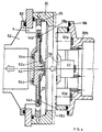
- the system comprises a first chamber 1 and a second chamber 2, which communicate with one another via a connection opening 4.
- the first chamber 1 designed as a buffer chamber, has (FIG. 2) a feed or removal opening 6 - a lock opening, which can be sealed with a driven feed and closure plate 8.
- a rotary drive 10 is provided which drives a carousel 14 via a drive axis 12.
- the latter comprises a transfer plate 16, on which receptacles 20 for circular workpieces 22 are arranged via leaf springs 18 (see also FIG. 2a) , Due to the leaf spring suspension, the receptacles 20, as shown in FIG. 1 at s 1, can be bent out in a radially resilient manner.
- the eight receptacles 20 provided on the carousel 14 are essentially designed as a frame, such as in particular in Fig. 2a. They point, viewed perpendicular to the expansion surface of the workpieces 22, a through opening 24 and, for reasons of clarity, only shown in FIG. 2a, a pliers-like acting hard holding mechanism 26 for the workpieces 22 above the through opening 24. Due The edge opening 24 (FIG. 2a) of the leaf springs 18 leaves the passage opening 24 free.
- the workpieces here storage plates, have a center opening 28.
- recordings 20 are rotated sequentially via the openings 4 and 6 of the chamber 1
- a laser base 29 is rigidly mounted on the housing of the chamber 1, which is aligned with the two openings 4 and 4 provided here, for example 6, accordingly, two plates 30a and 30b which can be radially extended and retracted independently of one another are arranged.
- the drive elements for the plates 30a and 30b are sealed or encapsulated by bellows 32a, b.
- Pneumatic control lines 34a and b are routed into block 29, as shown schematically in FIG. 1.
- the chamber 1 has a pump connection 36 for conditioning it, optionally also gas connections.
- the opening area at the opening 6 acts as the actual opening and closing Outlet lock for workpieces, while chamber 1 itself conditioning from the atmosphere introduced workpieces are used before they are countered by opening 4 in a manner to be described a processing station to be funded.
- the workpiece 22 is taken over by the feed / closing plate 8 from the receptacle 20 after the holding mechanism 26 has been released by the action of an actuating plunger, as shown in FIG. 2a at s 3 .
- the feed / closing plate 8 can now be lifted off, the machined workpiece is removed from it and a new one to be machined is inserted.
- the plate 8 is again sealed with the workpiece to be newly machined, the holding mechanism 26 takes over the workpiece to be newly machined on the now free receptacle 20, whereupon the plate 30a is moved into the return position shown in dashed lines in FIG. 2. This means that the carousel is free to turn one cycle further in the direction of s 2 .
- the opening 6 can be connected to a pump via a pump connection 42 be connected if the highest purity requirements are placed on the atmosphere in chamber 1.
- a pump connection 42 be connected if the highest purity requirements are placed on the atmosphere in chamber 1.
- the dilution ratio given by the volume in the opening area 6 to the volume of the chamber 1 sufficient to usually ensure a sufficient purity of the atmosphere in chamber 1.
- the plate 8 can be designed as a transport plate and part of a transport mechanism be in another chamber flanged to opening 6 or it can be of a different type Transport mechanism Feed or remove workpieces through carousel 14 through opening 6. Furthermore, it is easily possible, for example in the radial position B, a removal lock To provide, for example, constructed the same as that described in connection with the opening 6 and feed the workpieces to chamber 1 in two separate areas and feed them back remove.
- more than two plates 30 can be provided by a corresponding number to use openings provided in chamber 1, in extreme cases as many as receptacles 20 are provided are.
- the transport path for the workpieces is too large from their entry into chamber 1 their output from the chamber 1 towards a processing station much longer than the transport route from a processing station back into chamber 1 and from there to dispense the workpiece from the Chamber 1.
- chamber 1, however formed is used as a conditioning chamber is used for workpieces before their processing
- the transport route for workpieces from a receiving opening to a discharge opening for workpieces to be machined is longer than the transport path for machined workpieces from a relevant opening to a related opening.
- a transport star 44 with, for example, six transport arms 46 is provided in the chamber 2, which driven by a drive 48, via axis 50.
- a drive 48 via axis 50.
- Vacuum-sealed drive elements arranged radially forwards and backward-driving plate 52.
- the plates are 52 via opening 4 to chamber 1, on the one hand, and to one or more additional opening (s) 54 pivotable, on which, as in the example shown, one or more processing stations (s) are arranged can be and / or further transport chambers or lock chambers.
- a processing chamber 56 is provided.
- the central masking is carried out by a loosely supplied masking element depending on the workpiece to be machined, which, as will be described, before machining applied to the workpieces and removed after machining.
- the masking organs 58 which, after their processing, are applied to the workpieces returned on the plates 52, are removed in the area of the opening 4 from these already machined workpieces and one newly applied to one of the plates 52 in the chamber 2 applied workpiece, after that by turning of the transport star 44 is brought into the processing position.
- chamber 30b is on the non-rotating plate 1 an electromagnet arranged centrally.
- a disk-shaped workpiece 22 of the type mentioned is transported into the position shown in FIG. 1 opposite the opening 4.
- the corresponding plate 52 is placed with seals 62 close to the edge of the opening 4.
- the workpiece 22 riding on it, held by a magnet 64, preferably a permanent magnet, is thus inserted into the opening 4.
- a magnet 64 preferably a permanent magnet
- the plate 30b presses this empty receptacle 20 tightly onto the chamber 1 via seals 66 and seals 68 -side border of opening 4, so that the two chambers 1 and 2 are sealed, possibly vacuum-tight, during the rotational movement of the transport star 44.
- the electromagnet 60 on the plate 30b is activated, the masking member 58, made of magnetic material, is gripped and out of engagement with the workpiece by the withdrawal of the plate 30b 22 and brought the plate 52.
- the holding mechanism 26 according to FIG. 2a grips the machined workpiece 22 in the receptacle 20.
- the carousel is retracted 14 further rotated by one cycle in direction s 2 , whereby a receptacle 20, which is now loaded with a non-machined workpiece, is rotated via the opening 4.
- the previously treated workpiece freed from the masking member is now in its angular position B with its associated receptacle 20 as shown in FIG. 2.
- the electromagnet 58 is now deactivated, whereby the magnet 64, the masking member 58 with the workpiece pulls and holds on the plate 52 due to the tappet, which is built tightly, preferably vacuum-tight (bellows) 70, the retention mechanism 26 is released for this.
- the workpiece is now masked on the plate 52.
- the receptacle 20 is empty and ready to be received of a machined workpiece in the next cycle.
- the freshly loaded plate 52 is retrieved, the chamber separation is ensured by plate 30b and empty receptacle 20 by rotating the transport star 44 on the one hand the workpiece just loaded is rotated further against its machining position, on the other hand, an already machined one is rotated into position with respect to the empty receptacle 20 is e.g. arranged on the receptacle 20 and has 6 lock sealing in the system shown here on the opening Task.
- the seals 66 and / or 62 can also be used as diffusion gap seals be formed if there is a vacuum-tight separation in less delicate machining processes between the chambers 1 and 2 is not necessary or for example downstream of the chamber 2 Have processing and / or transport chambers for separation organs and conditioning agents.
- processing stations can also be provided on the chamber 2 and / or some of the openings provided open into further transport or distribution chambers or others Lock chambers.
- the system shown also becomes a chamber 2 evacuated or conditioned.
- the control lines for driving the plates 52 are (not shown) through the axis 50 of the star 44 out.
- masking members 58 become when they are processed are used up, e.g. if after several runs the coating has become too thick, not returned to chamber 2, but are e.g. with the plate 30b, no longer lifted off and on machined workpiece remaining ejected. Since this is planned in advance, an unprocessed one with the workpiece 20, as described above, newly supplied workpiece, already with a masking member 58 entered into the chamber 1, whereby the disused masking member 58 is replaced.
- the present invention was based on a preferred special embodiment according to the 1 to 2a.
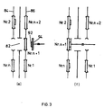
- FIG. 3 it is shown in a basic manner how fundamentally the mask change between two transport elements takes place if the relevant concept according to FIGS. 1, 2, 2a is followed.
- two chambers 80 and 78 are separated by the partition 76 with opening 82.
- a transport device is arranged in each chamber, shown schematically here as belt conveyors 84 and 86, respectively.
- Controllable holding members for the workpieces 88 are provided on each of the conveyors, as shown schematically at 90.
- the direction of transport of the workpieces 88 against the machining position takes place from chamber 78 into chamber 80, as represented by s 5 .
- the system will now be put into operation.
- the transport device 84 is empty, while with the transport device 86 workpieces 88 are supplied together with the masking members 92 designed as separate parts in the direction indicated by s 6 .
- the first workpiece no. 1 is conveyed through opening 82 and, as shown in FIG. 3b, is pushed by conveyor 86 through conveyor 82 through opening 82 into conveyor 84 by means of transverse transport member 94, for example in the form of a ram.
- the conveyor 84 is now clocked further in the direction s 7 , for example, as shown in FIG. 3b.
- N workpieces can be applied to the conveyor 84.
- workpiece no. 1 again in front of the opening 82 according to FIG. 3c.
- the workpiece No. (n + 1) on the conveyor 86 is now supplied without masking 92.
- the machined workpiece no. 1 from the sponsor 84 transferred to the conveyor 86 and, on the other hand, the masking member 92 from the workpiece no. 1 lifted off.
- the conveyor 86 is then moved one step further in the direction s 6. This creates the situation shown in FIG. 3e: the machined workpiece no. 1 is conveyed to an outlet from chamber 78, while workpiece no. (n + 1) lies above the opening 82. With the transverse transport member 94, the masking member 92, which has already passed through opening 76 to opening 82 through chamber 76, is placed on the unprocessed workpiece no. (n + 1) and this workpiece, as shown in FIG. 3f, is transferred from conveyor 86 through opening 82 to conveyor 84
- FIG 4 shows a schematically illustrated section with the opening 4 on the system according to FIG Fig. 1 shows a further embodiment of the system, in which peripheral masking elements 58p, such as the masking member 58 described above.
- the plate 52 with seals 62 carries in the illustrated embodiment, which is not necessarily to be coupled with the masking concept mentioned, a vehicle plate 52a, which is magnetically, preferably by means of permanent magnets 64a, on the plate 52, is supported.
- the vehicle panel 52a in turn supports plate- 52-sided peripheral magnets 64 p and the central magnet 64.
- Electromagnets 60 p for the peripheral masking element 58 p and 60 for the central 58 are provided on the plate 30 b . P with the magnet 60 passing the peripheral masking member 58p is accomplished analogously to the above with respect to the masking member 58th
- the vehicle plate 52a can be a workpiece adapter plate, which corresponds in each case to be machined workpieces 22 is replaced. It runs together with the respective Workpiece 22 at least part of the workpiece transport path. As shown schematically, the Retaining mechanism 26 when the vehicle plate 52a is provided on the latter.
- FIG. 5 shows the generality of the masking method or the system described for this, its basic principle is shown.
- a conveyor 100 as shown schematically, Workpieces 102a, without masking, one along the conveyor 100 and thus the path of movement B of the workpieces 102 acting application station 104 supplied by a magazine 106 with loose masking elements 108 is fed.
- Output side of the application station 104 i.e. the station at which Masking elements 108 are applied to the workpieces 102a, which are now with the masking element 108 provided workpieces 102b to one or more processing stations, generally shown in Fig. 5 with the vacuum surface processing assembly 110, wherein the mentioned workpieces 102b can be processed on one or two sides or all around.
- the output side of the arrangement 110 the now further machined workpieces 102b are machined along the path of motion B Workpieces acting removal station 112 fed and leave the removal station 112 as now processed Workpieces 102c, without masking element 108.
- the masking elements removed at station 112 108 are either fed back to the application station 104 or, if after several Feedback cycles are consumed by the action of the machining assembly 110, as shown at 114, withdrawn from circulation. This is done via a schematically illustrated controlled selection unit 116.
- a carousel 124 is provided in the transport chamber 120, which can be conditioned by itself and / or through at least one of the at least two provided chamber openings 122, which, as shown at ⁇ 1 , is driven in a controlled rotary manner. Regardless of the type, any controlled holding members 125 for workpieces 126 are provided.
- disk-shaped workpieces 126 are, for example, held and transported on the carousel 120 in such a way that their disk surfaces span a cylindrical surface when rotated about the axis of rotation of the carousel 124.
- the axis of rotation A 124 of the carousel 124 in a preferred variant, in a rotationally fixed, radially controlled manner, they can be extended or retracted, push elements 128 are provided. If they are non-rotatable, their number is equal to the number of openings 122 to be operated in the chamber 120, which number does not necessarily have to be the number of openings 120 provided at all in the chamber 120 and passed through by the workpieces.
- the carousel 124 is preferably rotated in steps, so that one receptacle 125 in each case is aligned with a chamber opening 122 to be operated, whereupon said chamber opening 122 permanently assigned pushing element 128, the positioned workpiece 126 is discharged in the direction out of the chamber 120 , or, conversely, a workpiece from outside the chamber 120 through said opening 122 is retrieved or retrieved.
- Such a transport chamber 120 can do more in a specifically conditioned atmosphere
- Workpieces 126 are temporarily stored as thrust members 128 are provided. It will be the rotary motion about the axis 124 and the radial movement, as carried out with the thrust members 128, with which the Realization of the corresponding drives and control lines is significantly simplified.
- the thrust members 128 are not mandatory, but preferred. It is entirely possible to arrange the thrust members 128 at an oblique angle to the axis A 124 , as indicated by dash-dotted lines in FIG. 6, and accordingly to provide the holders on the carousel and the openings in the chamber 120. Furthermore, it is also possible to provide two or more layers of workpieces on the carousel shown in FIG. 6, as shown in dashed lines, viewed in the axial direction A 124 , and to operate chamber openings 122, or even how, by means of push elements 128 staggered in this axial direction shown with v, the intended thrust members 128 probably still to be provided in a rotationally fixed manner, but displaceable in a controlled manner in the axial direction. As shown in Fig.
- FIG. 7 Another is shown in FIG. 7, which enables to significantly reduce the height of the transport chamber 120.
- the carousel 124 is designed here that the smallest workpiece dimension, when they are designed as disc-shaped workpieces 126 Thickness expansion, is parallel to the carousel axis 124.
- the thrust members 128 are formed and the intended openings 122a become slits.
- FIGS. 1, 2. shows a cross-sectional representation of a further embodiment variant of a chamber 2 according to FIGS. 1, 2. It comprises a drive motor 130, on the axis of which, as the spatial axis A and physical drive axis 133, at least one transport arm 135 is angled with an axis A 135 , for example angled at 45 ° to the spatial axis A, by means of the motor the drive axis 133, as in ⁇ 2 , rotated, the transport arm (s) 135 sweeps over a conical surface with here, for example, 45 ° cone opening angle öff. 7, the chamber K has two openings to be operated.
- a first opening 137 is, for example and, as shown, designed directly as a lock opening.
- another chamber 180 constructed, for example, according to the principle of the chamber according to FIGS. It comprises a frame 139, flanged to it an up and down frame 141. Inside the driven up and down frame 141 there is a sealing frame 142 which defines the lock volume 143 with a normal A 143 .
- the lock opening 137 further comprises a cover 145, which can be displaced linearly in the x direction, for example. It can of course also be pivoted about an axis vertical in FIG. 7 for opening and closing. In its closed, illustrated position, it is sealingly placed on the sealing frame 142 by lowering the intermediate frame 141 in the y direction.
- the lock opening 137 is thus sealed off from the surroundings U.
- the transport arm 135 carries, at the end, a plate 149 as a carrier part, on which a workpiece to be treated, in the example shown a storage disk 151, rests.
- the plate 149 on the transport arm 135 can be retrieved from its seat (shown) on the sealing frame 142 against the spatial axis A and the lock can thus be opened on the transport device side.
- the plate 149 need not be close to the frame 142 if the atmosphere in chamber K does not have to maintain the highest purity requirements.
- the workpiece 151 is conveyed with the transport arm by rotating the shaft 133 by means of the motor 130 to the second opening 157 shown.
- the radial drive mechanism on the transport arm 135, is, which is essential, provided directly on the rotatable transport arm and with a bellows 153 vacuum-tight against the environment in the Chamber K sealed.
- the workpiece 151 namely the disk
- the opening 157 defines the opening surface normal A 157 .
- the transport plate 149 with the workpiece 151 is raised again into the position shown by means of the aforementioned pneumatic lifting mechanism on the arm 135, so that the plate 149 now lies sealingly against the edge of the opening 157.
- the chamber K is preferably constructed to be vacuum-tight Purpose (not shown), at the stations coupled to the openings of the chamber K and / or Transport chambers and / or on the chamber K itself and / or on the lock opening 137, devices intended to selectively set respective atmospheres, i.e. there will be evacuation connections and / or gas inlets are provided.
- a pump connection 160 for chamber K and possibly the lock opening 137 are shown in FIG. 8.
- Fig. 10 the chamber, part of a system in the configuration according to Fig. 9, is shown in supervision.
- the same reference symbols denote the same components.
- six transport arms 135a to 135f are arranged around the axis A, analogously as shown in FIG. 9, and they alternately operate, for example, a lock station 158a for the input and output of disks 151 and a transport chamber 158b with stations 158b 1 , and others five chambers or processing stations through openings 157a to 157e.
- the opening 157b is e.g. a transport chamber 158b with carousel and pushing elements, analogous to Chamber 1 or those explained with FIGS. 6 and 7, assigned.
- This chamber 158b is with further processing stations and / or other transport stations connected.
- the opening 157c is, for example with another chamber 158c of the type according to chamber 2 of FIG. 1 and how it is further related 8 was explained, the latter in turn with further processing and / or transport and / or lock chambers.
- the constellation of the entire system shown is only an example of this deliver, as flexible, modular, both with chambers of the type according to chamber 1 of Fig. 1 - 2a and / or Type according to chamber 2 of Fig. 1 - 2a systems can be put together. It is supposed to be about this flexibility 10, the chamber type symbols to be defined later in FIG. 10 are used.
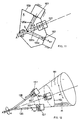
- FIG. 11 the basic principle of the chamber K explained with reference to FIGS. 1, 2, 8 to 10 is shown schematically.
- the three transport arms 135a to 135c shown here rotating about the spatial axis A
- the entered three openings 157 are operated, for example.
- the chamber K is surrounded by the boundary 159, entered schematically.
- the transport device sweeps over a conical surface with an opening angle ⁇ and serves the openings 157, which define the surface normals 157.
- the latter are directed in the direction of surface lines of the swept cone.
- the openings 157 lie on a great circle of the swept cone surface, ie they are all the same distance from the tip S of the cone swept by the arms 135.
- FIG. Another possibility is shown in FIG.
- the arms 135, as again shown at 167, can also be extended or retrieved and carry a transport plate 149a.
- the cone angle ⁇ can be adjusted so that cones with different opening angles ⁇ can be covered. Openings 157 arranged in any way can therefore be operated within wide limits.
- the support plate 149a is angled at an angle ⁇ ⁇ 90 ° on the respective arm 135 and, as shown at p, rotatable about the arm axis A 135 .
- the arms 135 are L-shaped and supported so that they are parallel to the axis of rotation A lie. If the spatial or rotational axis A is vertical, this has the essential advantage that workpieces do not need to be held on plates 149.
- the drives for the movement of the plates 149 lie within the bellows 153.
- a lock chamber by means of which workpieces only in the direction of the vacuum surface treatment be transported through.
- a transport chamber of the type as it is based on or through chamber 1 in FIGS. 1 and 2 and in 6, 7 has been illustrated and explained.
- FIG. 8 A chamber of the chamber 2 type of FIG. 1 and as further described in connection with FIGS. 8 to 14 has been illustrated and explained.
- a chamber in which workpieces are moved between at least two openings with what the chambers EASK, ESK, ASK, RAKAK and RADK are included, but in particular also chambers with different transport mechanisms than those shown in relation to the RAKAK and RADK chambers and described.
- FIG. 16 shows some configurations of plants in which at least one of the chambers is one RAKAK or RADK chamber. From this it can be seen that the two chamber types and others well-known chambers with maximum flexibility, modular system configurations can be put together with or without the integration of the masking concept according to FIG. 5. The procedure according to the invention is particularly suitable for processing magneto-optical storage disks.
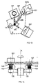
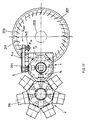
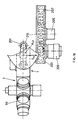
- FIGS. 17 and 18 A further preferred system configuration is shown schematically in FIGS. 17 and 18, each in a top view and in a side view. It comprises the chamber 2, as was explained in particular with reference to FIGS. 1 and 2, and the chamber 1, which is also described there.
- the disc-shaped substrates are picked up in the position P IN , as shown schematically, by means of the plates 149, which can be axially moved back and forth, and brought into the position on the opening 6 by rotating the robot arm 201. There, as already described with reference to FIG. 2, they are transferred to chamber 1.
- the carousel 14 then rotates further in the direction S 2 by an angle of rotation increment.
- the disk-shaped substrate that has just been inserted lies in position P 3 in the carousel.
- a degassing chamber 203 is arranged below the chamber 1, which comprises a transport turntable 207 driven by a central drive 205.
- the degassing chamber 203 is pumped separately by a vacuum pump 209.
- a transport slide (not shown) from the upper position in chamber 1 to the one below in the degassing chamber 203.
- the drive plate 205 rotates the transport plate 207 in chamber 203 by an angle increment in the direction indicated by S 207 in FIG. 17.
- one of the substrates 211 comes to lie in the position below P 3 , which has completed a complete circulation in the chamber 203.
- the last-mentioned substrate is now raised in the direction S A from the chamber 203 in position P 3 in chamber 1 and takes up the space on the carousel 14 that was just occupied by a substrate newly fed to the chamber 203.
- the carousel 14 in chamber 1 is then rotated further by an angle of rotation increment in the direction S 2 .
- the vacuum pump 209 ensures that degassing products can be removed from chamber 203. It creates a pressure gradient in chamber 203 towards the pump 209 ensured, as shown in dashed lines at ⁇ p in FIG. 18.
Landscapes
- Chemical & Material Sciences (AREA)
- Organic Chemistry (AREA)
- Engineering & Computer Science (AREA)
- Materials Engineering (AREA)
- Mechanical Engineering (AREA)
- Metallurgy (AREA)
- Chemical Kinetics & Catalysis (AREA)
- Physical Vapour Deposition (AREA)
- Specific Conveyance Elements (AREA)
- Automatic Assembly (AREA)
- Chemical Vapour Deposition (AREA)
- Manufacturing Of Magnetic Record Carriers (AREA)
- Manufacturing Optical Record Carriers (AREA)
Applications Claiming Priority (5)
| Application Number | Priority Date | Filing Date | Title |
|---|---|---|---|
| CH311992 | 1992-10-06 | ||
| CH311992 | 1992-10-06 | ||
| CH75793 | 1993-03-11 | ||
| CH75793 | 1993-03-11 | ||
| EP93114639A EP0591706B1 (fr) | 1992-10-06 | 1993-09-11 | Enceinte pour le transport des substrats |
Related Parent Applications (1)
| Application Number | Title | Priority Date | Filing Date |
|---|---|---|---|
| EP93114639A Division EP0591706B1 (fr) | 1992-10-06 | 1993-09-11 | Enceinte pour le transport des substrats |
Publications (3)
| Publication Number | Publication Date |
|---|---|
| EP1179611A2 true EP1179611A2 (fr) | 2002-02-13 |
| EP1179611A3 EP1179611A3 (fr) | 2002-04-17 |
| EP1179611B1 EP1179611B1 (fr) | 2004-09-15 |
Family
ID=25685591
Family Applications (2)
| Application Number | Title | Priority Date | Filing Date |
|---|---|---|---|
| EP01119538A Expired - Lifetime EP1179611B1 (fr) | 1992-10-06 | 1993-09-11 | Enceinte pour le transport des substrats |
| EP93114639A Expired - Lifetime EP0591706B1 (fr) | 1992-10-06 | 1993-09-11 | Enceinte pour le transport des substrats |
Family Applications After (1)
| Application Number | Title | Priority Date | Filing Date |
|---|---|---|---|
| EP93114639A Expired - Lifetime EP0591706B1 (fr) | 1992-10-06 | 1993-09-11 | Enceinte pour le transport des substrats |
Country Status (3)
| Country | Link |
|---|---|
| US (4) | US5590994A (fr) |
| EP (2) | EP1179611B1 (fr) |
| JP (2) | JP3761905B2 (fr) |
Cited By (3)
| Publication number | Priority date | Publication date | Assignee | Title |
|---|---|---|---|---|
| DE10215040A1 (de) * | 2002-04-05 | 2003-11-13 | Leybold Optics Gmbh | Vorrichtung und Verfahren zum Be- und Entladen einer Vakuumkammer |
| DE10205167C5 (de) * | 2002-02-07 | 2007-01-18 | Von Ardenne Anlagentechnik Gmbh | In-Line-Vakuumbeschichtungsanlage zur Zwischenbehandlung von Substraten |
| CN119133081A (zh) * | 2024-11-08 | 2024-12-13 | 浙江丽水中欣晶圆半导体科技有限公司 | 一种测量外延片的外延层厚度的装置及其测量方法 |
Families Citing this family (34)
| Publication number | Priority date | Publication date | Assignee | Title |
|---|---|---|---|---|
| CH691377A5 (de) * | 1992-10-06 | 2001-07-13 | Unaxis Balzers Ag | Kammeranordnung für den Transport von Werkstücken und deren Verwendung. |
| EP1179611B1 (fr) * | 1992-10-06 | 2004-09-15 | Unaxis Balzers Aktiengesellschaft | Enceinte pour le transport des substrats |
| FR2747111B1 (fr) * | 1996-04-03 | 1998-04-30 | Commissariat Energie Atomique | Systeme d'accouplement pour un transfert confine d'un objet plat d'une boite de confinement vers une unite de traitement de l'objet |
| US5882171A (en) * | 1996-10-01 | 1999-03-16 | Balzers Aktiengesellschaft | Transport and transfer apparatus |
| JP4653263B2 (ja) | 1996-12-23 | 2011-03-16 | オー・ツェー・エリコン・バルザース・アクチェンゲゼルシャフト | 真空処理装置 |
| DE19715151A1 (de) * | 1997-04-11 | 1998-10-15 | Leybold Systems Gmbh | Verfahren zum Be- und Entladen einer evakuierbaren Behandlungskammer und Handlingsvorrichtung zur Durchführung des Verfahrens |
| DE59805566D1 (de) * | 1997-04-11 | 2002-10-24 | Leybold Systems Gmbh | Verfahren und Vorrichtung zum Be- und Entladen einer evakuierbaren Behandlungskammer |
| US6391377B1 (en) * | 1997-07-08 | 2002-05-21 | Unaxis Balzers Aktiengesellschaft | Process for vacuum treating workpieces, and corresponding process equipment |
| TW589391B (en) * | 1997-07-08 | 2004-06-01 | Unaxis Trading Ag | Process for vacuum treating workpieces, and corresponding process equipment |
| CH692741A5 (de) * | 1997-07-08 | 2002-10-15 | Unaxis Trading Ltd C O Balzers | Verfahren zur Herstellung in Vakuum oberflächenbehandelter Werkstücke und Vakuumbehandlungsanlage zu dessen Durchführung |
| DE19819726A1 (de) * | 1998-05-02 | 1999-11-04 | Leybold Systems Gmbh | Vakuumbehandlungsanlage zum Aufbringen dünner, harter Schichten |
| US6162299A (en) | 1998-07-10 | 2000-12-19 | Asm America, Inc. | Multi-position load lock chamber |
| US6264804B1 (en) | 2000-04-12 | 2001-07-24 | Ske Technology Corp. | System and method for handling and masking a substrate in a sputter deposition system |
| US6962471B2 (en) * | 2000-10-26 | 2005-11-08 | Leica Microsystems Jena Gmbh | Substrate conveying module and system made up of substrate conveying module and workstation |
| NL1024215C2 (nl) * | 2003-09-03 | 2005-03-07 | Otb Group Bv | Systeem en werkwijze voor het behandelen van substraten, alsmede een gebruik van een dergelijke systeem en een transportinrichting. |
| WO2008004253A1 (fr) * | 2006-07-03 | 2008-01-10 | Valiani Srl | Système pour le changement rapide de tête sur des machines de fonctionnement |
| US8752449B2 (en) | 2007-05-08 | 2014-06-17 | Brooks Automation, Inc. | Substrate transport apparatus with multiple movable arms utilizing a mechanical switch mechanism |
| KR101660894B1 (ko) | 2007-06-27 | 2016-10-10 | 브룩스 오토메이션 인코퍼레이티드 | 다차원 위치 센서 |
| CN101855811B (zh) * | 2007-06-27 | 2013-11-20 | 布鲁克斯自动化公司 | 具有提升能力和减少的齿槽特性的电机定子 |
| US8283813B2 (en) | 2007-06-27 | 2012-10-09 | Brooks Automation, Inc. | Robot drive with magnetic spindle bearings |
| US8823294B2 (en) * | 2007-06-27 | 2014-09-02 | Brooks Automation, Inc. | Commutation of an electromagnetic propulsion and guidance system |
| WO2009003193A1 (fr) | 2007-06-27 | 2008-12-31 | Brooks Automation, Inc. | Retour d'informations de position pour moteur autoporteur |
| US9752615B2 (en) | 2007-06-27 | 2017-09-05 | Brooks Automation, Inc. | Reduced-complexity self-bearing brushless DC motor |
| JP2011514652A (ja) * | 2007-07-17 | 2011-05-06 | ブルックス オートメーション インコーポレイテッド | チャンバ壁に一体化されたモータを伴う基板処理装置 |
| USD635597S1 (en) * | 2008-11-17 | 2011-04-05 | Applied Materials, Inc. | Lift pin |
| USD640715S1 (en) * | 2008-11-17 | 2011-06-28 | Applied Materials, Inc. | Lift pin assembly |
| USD650818S1 (en) * | 2008-12-19 | 2011-12-20 | Applied Materials, Inc. | Inner lift pin |
| DE102009037290A1 (de) * | 2009-04-24 | 2010-11-11 | Singulus Technologies Ag | Transporteinrichtung mit einem auslenkbaren Dichtrahmen |
| DE102009037291B4 (de) | 2009-04-24 | 2020-06-10 | Singulus Technologies Ag | Verfahren und Vorrichtung zum Ein- und Ausschleusen von Substraten |
| CN104743351B (zh) * | 2013-12-30 | 2016-09-07 | 基准精密工业(惠州)有限公司 | 加工室 |
| CN107416466B (zh) * | 2017-07-26 | 2019-03-15 | 佛山汉格斯环保科技有限公司 | 一种用于煤化工的磁力给料机 |
| CN114144542B (zh) * | 2020-07-30 | 2022-09-06 | 株式会社新柯隆 | 移载装置及使用了该移载装置的成膜装置 |
| CN112481588B (zh) * | 2020-10-20 | 2023-06-09 | 广东振华科技股份有限公司 | 全自动快速溅射镀膜生产设备 |
| CN120600677B (zh) * | 2025-08-08 | 2025-10-10 | 无锡亘芯悦科技有限公司 | 一种晶圆传输系统及半导体设备 |
Family Cites Families (49)
| Publication number | Priority date | Publication date | Assignee | Title |
|---|---|---|---|---|
| DD250248A (fr) * | ||||
| US3477050A (en) * | 1968-02-13 | 1969-11-04 | Wehr Corp | Latch assembly for material handling magnet |
| US3968885A (en) * | 1973-06-29 | 1976-07-13 | International Business Machines Corporation | Method and apparatus for handling workpieces |
| JPS5350224Y2 (fr) * | 1973-09-25 | 1978-12-01 | ||
| US3960279A (en) * | 1973-11-09 | 1976-06-01 | General Motors Corporation | Magnetic alignment for semiconductor device bonding |
| CH573985A5 (fr) * | 1973-11-22 | 1976-03-31 | Balzers Patent Beteilig Ag | |
| DE2529018A1 (de) * | 1975-06-28 | 1977-01-13 | Ibm Deutschland | Einrichtung zur automatischen einzelfoerderung von werkstuecken in eine unter unterdruck stehende bearbeitungsstation |
| GB2054345B (en) * | 1979-06-19 | 1984-02-22 | Peanuts Ltd Q | Fluidised bed |
| US4433951A (en) * | 1981-02-13 | 1984-02-28 | Lam Research Corporation | Modular loadlock |
| US4498832A (en) * | 1982-05-21 | 1985-02-12 | The Boc Group, Inc. | Workpiece accumulating and transporting apparatus |
| JPS5950538A (ja) * | 1982-09-17 | 1984-03-23 | Hitachi Ltd | ウエハ搬送装置 |
| JPS6052574A (ja) * | 1983-09-02 | 1985-03-25 | Hitachi Ltd | 連続スパツタ装置 |
| DE3332033A1 (de) * | 1983-09-06 | 1985-03-21 | Bayer Ag, 5090 Leverkusen | Neue polyamidimide und ihre verwendung |
| GB8332394D0 (en) * | 1983-12-05 | 1984-01-11 | Pilkington Brothers Plc | Coating apparatus |
| JPS60238479A (ja) * | 1984-05-10 | 1985-11-27 | Anelva Corp | 真空薄膜処理装置 |
| US4534314A (en) * | 1984-05-10 | 1985-08-13 | Varian Associates, Inc. | Load lock pumping mechanism |
| US4588343A (en) * | 1984-05-18 | 1986-05-13 | Varian Associates, Inc. | Workpiece lifting and holding apparatus |
| DE3466135D1 (en) * | 1984-10-16 | 1987-10-15 | Ibm | Vacuum transfer device |
| US4735540A (en) * | 1985-11-15 | 1988-04-05 | Komag, Inc. | Robotic disk handler system |
| SU1302259A1 (ru) * | 1985-12-30 | 1987-04-07 | Предприятие П/Я В-8906 | Устройство дл отбора выборок изделий из ротора роторной машины |
| US4676884A (en) * | 1986-07-23 | 1987-06-30 | The Boc Group, Inc. | Wafer processing machine with evacuated wafer transporting and storage system |
| US5000652A (en) * | 1986-09-22 | 1991-03-19 | International Business Machines Corporation | Wafer transfer apparatus |
| US4886412A (en) * | 1986-10-28 | 1989-12-12 | Tetron, Inc. | Method and system for loading wafers |
| US4951601A (en) * | 1986-12-19 | 1990-08-28 | Applied Materials, Inc. | Multi-chamber integrated process system |
| US4795299A (en) * | 1987-04-15 | 1989-01-03 | Genus, Inc. | Dial deposition and processing apparatus |
| DE3716498C2 (de) * | 1987-05-16 | 1994-08-04 | Leybold Ag | Vorrichtung zum Ein- und Ausschleusen von Werkstücken in eine Beschichtungskammer |
| DE3827343A1 (de) * | 1988-08-12 | 1990-02-15 | Leybold Ag | Vorrichtung nach dem karussel-prinzip zum beschichten von substraten |
| US4851101A (en) * | 1987-09-18 | 1989-07-25 | Varian Associates, Inc. | Sputter module for modular wafer processing machine |
| DE3735284A1 (de) * | 1987-10-17 | 1989-04-27 | Leybold Ag | Vorrichtung nach dem karussell-prinzip zum beschichten von substraten |
| US5026239A (en) * | 1988-09-06 | 1991-06-25 | Canon Kabushiki Kaisha | Mask cassette and mask cassette loading device |
| US5061144A (en) * | 1988-11-30 | 1991-10-29 | Tokyo Electron Limited | Resist process apparatus |
| EP0389820B1 (fr) * | 1989-03-30 | 1993-06-16 | Leybold Aktiengesellschaft | Dispositif pour faire entrer ou sortir par une écluse une pièce dans une chambre à vide |
| DE3912295C2 (de) * | 1989-04-14 | 1997-05-28 | Leybold Ag | Katodenzerstäubungsanlage |
| JPH0336267A (ja) * | 1989-06-29 | 1991-02-15 | Ulvac Japan Ltd | 基板ホルダ |
| US5227708A (en) * | 1989-10-20 | 1993-07-13 | Applied Materials, Inc. | Two-axis magnetically coupled robot |
| US5224581A (en) * | 1989-12-14 | 1993-07-06 | Applied Materials, Inc. | Magnetic semiconductor wafers with handling apparatus and method |
| US5310410A (en) * | 1990-04-06 | 1994-05-10 | Sputtered Films, Inc. | Method for processing semi-conductor wafers in a multiple vacuum and non-vacuum chamber apparatus |
| US5145227A (en) * | 1990-12-31 | 1992-09-08 | The United States Of America As Represented By The Administrator Of The National Aeronautics And Space Administration | Electromagnetic attachment mechanism |
| JP2986121B2 (ja) * | 1991-03-26 | 1999-12-06 | 東京エレクトロン株式会社 | ロードロック装置及び真空処理装置 |
| DE4110490C2 (de) * | 1991-03-30 | 2002-02-28 | Unaxis Deutschland Holding | Kathodenzerstäubungsanlage |
| DE4117969C2 (de) * | 1991-05-31 | 2000-11-09 | Balzers Ag Liechtenstein | Vakuumkammer |
| US5139383A (en) * | 1991-07-23 | 1992-08-18 | Huntington Mechanical Laboratories, Inc. | Device for positioning objects within a sealed chamber |
| DE4227848B4 (de) * | 1991-11-28 | 2009-05-07 | Robert Bosch Gmbh | Bauteilträger und Verfahren zum Halten eines aus einem ferromagnetischen Werkstoff ausgebildeten Bauteils |
| EP1179611B1 (fr) * | 1992-10-06 | 2004-09-15 | Unaxis Balzers Aktiengesellschaft | Enceinte pour le transport des substrats |
| GB2272225B (en) * | 1992-10-06 | 1996-07-17 | Balzers Hochvakuum | A method for masking a workpiece and a vacuum treatment facility |
| US5863170A (en) * | 1996-04-16 | 1999-01-26 | Gasonics International | Modular process system |
| US5879128A (en) * | 1996-07-24 | 1999-03-09 | Applied Materials, Inc. | Lift pin and support pin apparatus for a processing chamber |
| US5882171A (en) * | 1996-10-01 | 1999-03-16 | Balzers Aktiengesellschaft | Transport and transfer apparatus |
| US5820329A (en) * | 1997-04-10 | 1998-10-13 | Tokyo Electron Limited | Vacuum processing apparatus with low particle generating wafer clamp |
-
1993
- 1993-09-11 EP EP01119538A patent/EP1179611B1/fr not_active Expired - Lifetime
- 1993-09-11 EP EP93114639A patent/EP0591706B1/fr not_active Expired - Lifetime
- 1993-10-05 US US08/131,669 patent/US5590994A/en not_active Expired - Lifetime
- 1993-10-06 JP JP25029493A patent/JP3761905B2/ja not_active Expired - Fee Related
-
1996
- 1996-10-10 US US08/728,610 patent/US5865588A/en not_active Expired - Lifetime
-
1999
- 1999-01-25 US US09/236,388 patent/US6096231A/en not_active Expired - Fee Related
-
2000
- 2000-05-18 US US09/572,873 patent/US6364955B2/en not_active Expired - Fee Related
-
2005
- 2005-11-09 JP JP2005325046A patent/JP4130675B2/ja not_active Expired - Fee Related
Cited By (4)
| Publication number | Priority date | Publication date | Assignee | Title |
|---|---|---|---|---|
| DE10205167C5 (de) * | 2002-02-07 | 2007-01-18 | Von Ardenne Anlagentechnik Gmbh | In-Line-Vakuumbeschichtungsanlage zur Zwischenbehandlung von Substraten |
| DE10215040A1 (de) * | 2002-04-05 | 2003-11-13 | Leybold Optics Gmbh | Vorrichtung und Verfahren zum Be- und Entladen einer Vakuumkammer |
| DE10215040B4 (de) * | 2002-04-05 | 2019-02-21 | Leybold Optics Gmbh | Vorrichtung und Verfahren zum Be- und Entladen einer Vakuumkammer |
| CN119133081A (zh) * | 2024-11-08 | 2024-12-13 | 浙江丽水中欣晶圆半导体科技有限公司 | 一种测量外延片的外延层厚度的装置及其测量方法 |
Also Published As
| Publication number | Publication date |
|---|---|
| US6364955B2 (en) | 2002-04-02 |
| JP3761905B2 (ja) | 2006-03-29 |
| US5865588A (en) | 1999-02-02 |
| EP1179611A3 (fr) | 2002-04-17 |
| JP2006143474A (ja) | 2006-06-08 |
| EP0591706A1 (fr) | 1994-04-13 |
| EP0591706B1 (fr) | 2002-04-24 |
| US6096231A (en) | 2000-08-01 |
| JP4130675B2 (ja) | 2008-08-06 |
| US20010001951A1 (en) | 2001-05-31 |
| US5590994A (en) | 1997-01-07 |
| EP1179611B1 (fr) | 2004-09-15 |
| JPH06264241A (ja) | 1994-09-20 |
Similar Documents
| Publication | Publication Date | Title |
|---|---|---|
| EP1179611B1 (fr) | Enceinte pour le transport des substrats | |
| DE69937483T2 (de) | Vakuumvorrichtung | |
| EP0312694B1 (fr) | Appareil suivant le principe à carrousel pour revêtir des substrats | |
| EP0518109B1 (fr) | Système de traitement sous vide | |
| DE3650057T2 (de) | System für Vakuumbehandlung. | |
| DE68928460T2 (de) | Maskenkassetten-Ladevorrichtung | |
| DE69302586T2 (de) | Halbleiterwafer transport-modul mit drehbarem und horizontal ausziehbarem halter | |
| DE69531365T2 (de) | Unterteilte Substrat Behandlungskammer | |
| EP0354294A2 (fr) | Appareillage de type carrousel pour le revêtement de substrats | |
| DE69108079T2 (de) | Sputteranlage. | |
| EP0343530A2 (fr) | Installation sous vide | |
| DE69525372T2 (de) | Sputter anlage mit eingebautem wartungsmodul | |
| DE4235677C2 (de) | Vakuumkammer, Vakuumbehandlungsanlage mit einer solchen Kammer sowie Transportverfahren | |
| WO1998014632A1 (fr) | Dispositif de transport et de transfert | |
| DE4235676C2 (de) | Vakuumkammer zum Transport scheibenförmiger Werkstücke in einer Vakuumanlage | |
| DE3856248T2 (de) | Siliciumwafer-handhabungssystem mit bernoulli-aufnahme | |
| DE4408947A1 (de) | Vakuumbehandlungsanlage und Ventilanordnung | |
| EP0492114A1 (fr) | Appareillage de pulvérisation | |
| CH691377A5 (de) | Kammeranordnung für den Transport von Werkstücken und deren Verwendung. | |
| DE4235678C1 (de) | Verfahren zur Oberflächenbehandlung eines Werkstückes, und Vakuumbehandlungsanlage zur Durchführung des Verfahrens | |
| DE60129975T2 (de) | Vorrichtung zur durchführung mindestens einer behandlung eines substrates | |
| EP1172842B1 (fr) | Station de revêtement pour des pièces en forme de disque | |
| CH686445A5 (de) | Kammer und Kammerkombination fuer eine Vakuumanlage und Verfahren zum Durchreichen mindestens eines Werkstueckes. | |
| DE19624609B4 (de) | Vakuumbehandlungsanlage zum Aufbringen dünner Schichten auf Substrate, beispielsweise auf Scheinwerferreflektoren | |
| EP0448782A2 (fr) | Dispositif de chargement et de déchargement d'une pièce dans une chambre à vide |
Legal Events
| Date | Code | Title | Description |
|---|---|---|---|
| PUAI | Public reference made under article 153(3) epc to a published international application that has entered the european phase |
Free format text: ORIGINAL CODE: 0009012 |
|
| AC | Divisional application: reference to earlier application |
Ref document number: 591706 Country of ref document: EP |
|
| AK | Designated contracting states |
Kind code of ref document: A2 Designated state(s): CH FR GB LI NL |
|
| PUAL | Search report despatched |
Free format text: ORIGINAL CODE: 0009013 |
|
| AK | Designated contracting states |
Kind code of ref document: A3 Designated state(s): CH FR GB LI NL |
|
| RIC1 | Information provided on ipc code assigned before grant |
Free format text: 7C 23C 14/56 A, 7H 01L 21/00 B, 7C 23C 14/04 B |
|
| 17P | Request for examination filed |
Effective date: 20020510 |
|
| 17Q | First examination report despatched |
Effective date: 20020808 |
|
| AKX | Designation fees paid |
Free format text: CH FR GB LI NL |
|
| GRAP | Despatch of communication of intention to grant a patent |
Free format text: ORIGINAL CODE: EPIDOSNIGR1 |
|
| GRAS | Grant fee paid |
Free format text: ORIGINAL CODE: EPIDOSNIGR3 |
|
| GRAA | (expected) grant |
Free format text: ORIGINAL CODE: 0009210 |
|
| AC | Divisional application: reference to earlier application |
Ref document number: 0591706 Country of ref document: EP Kind code of ref document: P |
|
| AK | Designated contracting states |
Kind code of ref document: B1 Designated state(s): CH FR GB LI NL |
|
| REG | Reference to a national code |
Ref country code: CH Ref legal event code: EP Ref country code: GB Ref legal event code: FG4D Free format text: NOT ENGLISH |
|
| GBT | Gb: translation of ep patent filed (gb section 77(6)(a)/1977) |
Effective date: 20041202 |
|
| PLBE | No opposition filed within time limit |
Free format text: ORIGINAL CODE: 0009261 |
|
| STAA | Information on the status of an ep patent application or granted ep patent |
Free format text: STATUS: NO OPPOSITION FILED WITHIN TIME LIMIT |
|
| ET | Fr: translation filed | ||
| 26N | No opposition filed |
Effective date: 20050616 |
|
| REG | Reference to a national code |
Ref country code: CH Ref legal event code: PFA Owner name: OC OERLIKON BALZERS AG Free format text: UNAXIS BALZERS AKTIENGESELLSCHAFT# #9496 BALZERS (LI) -TRANSFER TO- OC OERLIKON BALZERS AG#PATENTABTEILUNG POSTFACH 1000#9496 BALZERS (LI) |
|
| PGFP | Annual fee paid to national office [announced via postgrant information from national office to epo] |
Ref country code: NL Payment date: 20080903 Year of fee payment: 16 |
|
| REG | Reference to a national code |
Ref country code: NL Ref legal event code: V1 Effective date: 20100401 |
|
| PG25 | Lapsed in a contracting state [announced via postgrant information from national office to epo] |
Ref country code: NL Free format text: LAPSE BECAUSE OF NON-PAYMENT OF DUE FEES Effective date: 20100401 |
|
| PGFP | Annual fee paid to national office [announced via postgrant information from national office to epo] |
Ref country code: FR Payment date: 20110922 Year of fee payment: 19 Ref country code: GB Payment date: 20110907 Year of fee payment: 19 |
|
| PGFP | Annual fee paid to national office [announced via postgrant information from national office to epo] |
Ref country code: CH Payment date: 20111215 Year of fee payment: 19 |
|
| REG | Reference to a national code |
Ref country code: CH Ref legal event code: PL |
|
| GBPC | Gb: european patent ceased through non-payment of renewal fee |
Effective date: 20120911 |
|
| REG | Reference to a national code |
Ref country code: FR Ref legal event code: ST Effective date: 20130531 |
|
| PG25 | Lapsed in a contracting state [announced via postgrant information from national office to epo] |
Ref country code: GB Free format text: LAPSE BECAUSE OF NON-PAYMENT OF DUE FEES Effective date: 20120911 Ref country code: LI Free format text: LAPSE BECAUSE OF NON-PAYMENT OF DUE FEES Effective date: 20120930 Ref country code: CH Free format text: LAPSE BECAUSE OF NON-PAYMENT OF DUE FEES Effective date: 20120930 |
|
| PG25 | Lapsed in a contracting state [announced via postgrant information from national office to epo] |
Ref country code: FR Free format text: LAPSE BECAUSE OF NON-PAYMENT OF DUE FEES Effective date: 20121001 |