EP1180457A2 - Rétracteur de sangle - Google Patents
Rétracteur de sangle Download PDFInfo
- Publication number
- EP1180457A2 EP1180457A2 EP01119540A EP01119540A EP1180457A2 EP 1180457 A2 EP1180457 A2 EP 1180457A2 EP 01119540 A EP01119540 A EP 01119540A EP 01119540 A EP01119540 A EP 01119540A EP 1180457 A2 EP1180457 A2 EP 1180457A2
- Authority
- EP
- European Patent Office
- Prior art keywords
- take
- shaft
- rotating body
- fit
- webbing
- Prior art date
- Legal status (The legal status is an assumption and is not a legal conclusion. Google has not performed a legal analysis and makes no representation as to the accuracy of the status listed.)
- Granted
Links
- 238000010521 absorption reaction Methods 0.000 abstract description 6
- 238000010008 shearing Methods 0.000 abstract description 5
- 230000000694 effects Effects 0.000 description 6
- 239000012141 concentrate Substances 0.000 description 4
- 230000000452 restraining effect Effects 0.000 description 3
- 230000002093 peripheral effect Effects 0.000 description 2
- 230000001133 acceleration Effects 0.000 description 1
- 230000007423 decrease Effects 0.000 description 1
- 238000006073 displacement reaction Methods 0.000 description 1
- 239000000463 material Substances 0.000 description 1
Images

Classifications
-
- B—PERFORMING OPERATIONS; TRANSPORTING
- B60—VEHICLES IN GENERAL
- B60R—VEHICLES, VEHICLE FITTINGS, OR VEHICLE PARTS, NOT OTHERWISE PROVIDED FOR
- B60R22/00—Safety belts or body harnesses in vehicles
- B60R22/34—Belt retractors, e.g. reels
-
- B—PERFORMING OPERATIONS; TRANSPORTING
- B60—VEHICLES IN GENERAL
- B60R—VEHICLES, VEHICLE FITTINGS, OR VEHICLE PARTS, NOT OTHERWISE PROVIDED FOR
- B60R22/00—Safety belts or body harnesses in vehicles
- B60R22/34—Belt retractors, e.g. reels
- B60R22/341—Belt retractors, e.g. reels comprising energy-absorbing means
- B60R22/3413—Belt retractors, e.g. reels comprising energy-absorbing means operating between belt reel and retractor frame
-
- B—PERFORMING OPERATIONS; TRANSPORTING
- B60—VEHICLES IN GENERAL
- B60R—VEHICLES, VEHICLE FITTINGS, OR VEHICLE PARTS, NOT OTHERWISE PROVIDED FOR
- B60R22/00—Safety belts or body harnesses in vehicles
- B60R22/28—Safety belts or body harnesses in vehicles incorporating energy-absorbing devices
- B60R2022/286—Safety belts or body harnesses in vehicles incorporating energy-absorbing devices using deformation of material
-
- B—PERFORMING OPERATIONS; TRANSPORTING
- B60—VEHICLES IN GENERAL
- B60R—VEHICLES, VEHICLE FITTINGS, OR VEHICLE PARTS, NOT OTHERWISE PROVIDED FOR
- B60R22/00—Safety belts or body harnesses in vehicles
- B60R22/28—Safety belts or body harnesses in vehicles incorporating energy-absorbing devices
- B60R2022/286—Safety belts or body harnesses in vehicles incorporating energy-absorbing devices using deformation of material
- B60R2022/287—Safety belts or body harnesses in vehicles incorporating energy-absorbing devices using deformation of material of torsion rods or tubes
Definitions
- the present invention relates to a webbing retractor which, when a vehicle rapidly decelerates, tenses a webbing in a direction of restraining a vehicle occupant.
- the present invention relates to a webbing retractor which, when pulling-out of a webbing is impeded, allows the webbing to be pulled-out by a predetermined amount and can absorb energy.
- a webbing retractor which forms a seat belt device of a vehicle is usually provided with a lock mechanism which, at the time the vehicle rapidly decelerates, locks a spool (take-up shaft) so as to impede pulling-out of a webbing.
- Such a lock mechanism is a type which includes a lock base and a lock device.
- the lock base is disposed coaxially with the spool and is connected so as to be integral with the spool.
- the lock device engages with the lock base so as to impede rotation of the lock base, and indirectly impedes rotation of the spool.
- Such webbing retractors are equipped with a so-called force limiter mechanism which, when pulling-out of the webbing is impeded, allow the webbing to be pulled-out by a predetermined amount in order to limit the load applied to the vehicle occupant by the webbing to a given amount or less, and absorb energy.
- a force limiter mechanism is a structure in which one end portion of the torsion bar, which is disposed coaxially with the spool, is fixed to the spool, and the other end portion is connected so as to be integral with the aforementioned lock base.
- This absorbed energy is determined by the product of the load applied to the webbing (force limiter load) and the webbing pull-out amount (amount of rotation of the spool) .
- the force limiter load and the allowable amount of rotation of the spool are given, and there are limits on the amount of energy which can be absorbed.
- an object of the present invention is to provide a webbing retractor having a force limiter mechanism whose energy absorption amount is large and which can reliably absorb energy.
- a webbing retractor relating to a first aspect of the present invention is a retractor of a webbing belt which is elongated and belt-shaped and restrains a body of a vehicle occupant in a state in which the webbing belt is applied to the vehicle occupant, the webbing retractor comprising: (a) a take-up shaft to which a proximal end portion of the webbing belt is anchored, and due to the take-up shaft rotating in one direction around an axis of the take-up shaft, the take-up shaft takes-up the webbing belt from a proximal end side, and due to tensile force, toward a distal end side which is a side opposite to the proximal end portion, being applied to the webbing belt, rotational force in a pull-out direction, which is a direction opposite to a take-up direction, is applied to the take-up shaft; (b) a rotating body which is provided at a side of an axial direction of the take-up shaft so as to be coaxial
- the take-up shaft rotates in the pull-out direction in a state in which the lock device engages with the rotating body and rotation of the rotating body is limited in a case in which the vehicle rapidly decelerates
- the take-up shaft rotates relative to the rotating body.
- the fit-in portion of the energy absorbing member which is fit into the other of take-up shaft and the rotating body, attempts to rotate relative to the fixing portion of the energy absorbing member fixed to the one of the take-up shaft and the rotating body.
- the curved portion is formed so as to be bent from the fixing portion
- the fit-in portion is formed so as to be bent from the curved portion.
- the fixing portion and the fit-in portion are integral via the curved portion.
- the fit-in portion cannot merely rotate relative to the fixing portion, and the fit-in portion is forcibly pulled-out by the forcibly pulling-out device.
- the fit-in portion, which is bent from the curved portion is forcibly deformed and curved along an imaginary line extending in the curving direction of the curved portion.
- the take-up shaft can rotate in the pull-out direction by an amount corresponding to the amount that the fit-in portion is pulled-out by the forcibly pulling-out device. Pulling-out of the webbing belt by an amount corresponding to the permitted amount of rotation is possible, and energy corresponding to an amount of deformation of the fit-in portion is absorbed.
- the amount of absorbed energy which is due to the energy absorbing effect due to the curving (deformation) of the fit-in portion, is added to the amount of absorbed energy, which is due to the energy absorbing effect of the energy absorbing member such as the torsion bar or the like.
- the overall amount of absorbed energy of the webbing retractor can be increased.
- the curved portion is provided between the fixing portion and the fit-in portion. As seen from the fixing portion, this curved portion is curved toward the aforementioned other of the take-up shaft and the rotating body (i.e., the one of the take-up shaft and the rotating body into which the fit-in portion is fit) when the take-up shaft rotates in the pull-out direction relative to the rotating body.
- the curved portion when the curved portion is considered to be a portion of the fit-in portion, the curved portion can be considered to be a portion which is plastically deformed in advance in a direction of rotation of the aforementioned other of the take-up shaft and the rotating body (i.e., the one of the take-up shaft and the rotating body into which the fit-in portion is fit) when the take-up shaft rotates in the pull-out direction relative to the rotating body.
- the curved portion By plastically deforming the curved portion in advance in this way, the curved portion can easily be deformed in the direction along this deformation, i.e., in the rotating direction of the other of the take-up shaft and the rotating body. Stress does not concentrate at one portion of the energy absorbing member, and the energy absorbing member does not break. In this way, energy can be reliably absorbed during a predetermined period of time which is set in advance.
- Fig. 1 the structure of the main portions of a webbing retractor 10 relating to an embodiment of the present invention is illustrated in an exploded perspective view.
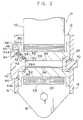
- Fig. 2 the structure of the webbing retractor 10 is illustrated in a front sectional view.
- the webbing retractor 10 has a frame 12.
- the frame 12 is formed by a pair of leg plates 14, 16 and a supporting plate 18.
- the leg plates 14, 16 are plate-shaped and oppose one another along the directions of thickness thereof.
- the supporting plate 18 connects ones of transverse direction end portions of the leg plates 14, 16, and is fixed to a side of a seat of a vehicle by a fastening device such as a bolt or the like.
- the frame 12 is therefore formed on the whole in a substantial U-shape as seen in plan view.
- a spool 20 which serves as a take-up shaft and whose axial direction is the transverse direction of the supporting plate 18 (the direction in which the leg plate 14 and the leg plate 16 oppose one another), is provided between the leg plate 14 and the leg plate 16 of the frame 12.
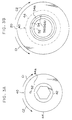
- the proximal end portion of an elongated, belt-shaped webbing belt 22 is anchored onto a portion of the outer periphery of the spool 20. Due to the spool 20 rotating in a take-up direction (the direction of arrow C1 in Figs. 3A and 3B), the webbing belt 22 is taken-up in layers onto the outer peripheral portion of the spool 20.
- the spool 20 rotates in a pull-out direction, which is opposite to the take-up direction (i.e., the spool 20 rotates in the direction of arrow C2 in Figs. 3A and 3B), such that the webbing belt 22 taken-up on the spool 20 is pulled-out.
- the spool 20 is formed overall in a tube shape, and a torsion bar 24 is accommodated in the interior of the spool 20 so as to be coaxial with the spool 20.
- the torsion bar 24 has a columnar bar main body 26.
- a substantially hexagonal-solid-shaped fixing portion 28 is formed at one end portion in the longitudinal direction (the leg plate 14 side end portion) of the bar main body 26.
- the fixing portion 28 is fixed to a sleeve 30 which is connected and fixed to the spool 20 at one axial direction side (the leg plate 14 side) of the spool 20.
- the fixing portion 28 is connected integrally to the spool 20 indirectly by the sleeve 30.
- a substantially hexagonal-solid-shaped fixing portion 32 is formed at the other end portion in the longitudinal direction (the leg plate 16 side end portion) of the bar main body 26.
- the fixing portion 32 is connected and fixed to a lock base 40 which serves as a rotating body and which is disposed at the axial direction other end side (the leg plate 16 side) of the spool 20.
- the lock base 40 has a substantially cylindrical small diameter portion 42.
- the small diameter portion 42 is fit into the spool 20 from the axial direction other end side of the spool 20, so as to be coaxial with the spool 20 and so as to basically rotate relative with respect to the spool 20.
- the fixing portion 32 is integrally connected and fixed to the small diameter portion 42, usually, the small diameter portion 42 does not rotate relative to the spool 20.
- a large diameter portion 44 whose diameter is greater than that of the small diameter portion 42, is formed integrally and coaxially with the other axial direction end side (the leg plate 16 side) of the small diameter portion 42.
- the large diameter portion 44 passes, substantially coaxially, through a ratchet hole 48 which is formed in the leg plate 16, and which is substantially circular, and at whose inner peripheral portion a ratchet 46 is formed.
- a lock member 50 serving as a lock device is provided at the large diameter portion 44.
- a V gear (not shown), which is provided coaxially with the large diameter portion 44 and so as to be able to rotate relative to the large diameter portion 44, rotates relative to the large diameter portion 44, the lock member 50 meshes with the ratchet 46 of the ratchet hole 48 such that rotation of the large diameter portion 44, i.e., the lock base 40, is limited.
- a fixing hole 52 having a bottom is formed in the large diameter portion 44 of the lock base 40.
- the fixing hole 52 is eccentric with respect to the axial center of the lock base 40, and opens at an end surface 44A at the side facing the spool 20.
- a guide groove 54 is formed in the end surface of the spool 20 at the end surface of the side facing the lock base 40.
- the guide groove 54 is ring-shaped and is coaxial with the spool 20.
- the radius of the guide groove is the same as the amount by which the fixing hole 52 is eccentric with respect to the axial center of the large diameter portion 44. Accordingly, as shown in Fig. 3B, the fixing hole 52 overlaps on the guide groove 54 along the axial direction of the spool 20 and the lock base 40, and even if the spool 20 rotates relative to the lock base 40, the fixing hole 52 always overlaps the guide groove 54.
- a fit-in hole 56 is formed in the spool 20.
- the fit-in hole 56 is a hole which has a bottom and which opens at the bottom portion of the guide groove 54. The direction of opening thereof is substantially parallel to the axial direction of the spool 20.
- the spool 20 and the lock base 40 are connected integrally by the torsion bar 24.
- the fit-in hole 56 is displaced by a predetermined angle, toward the pull-out direction, around the axial center of the spool 20 and the lock base 40. Note that it is not absolutely necessary for the opening direction of the fit-in hole 56 to be parallel to the axial direction of the spool 20, and the opening direction may be inclined with respect to the axial direction of the spool 20.
- a wire 60 serving as an energy absorbing member is disposed at a portion of the inner side of the guide groove 54.
- the wire 60 has a curved portion 62.
- the curved portion 62 is curved in an arc so as to correspond to the curvature of the guide groove 54.
- the entire length of the curved portion 62 corresponds to the length in the pull-out direction from the fixing hole 52 to the fit-in hole 56.
- the wire 60 is disposed in the guide groove 54 between the fixing hole 52 and the fit-in hole 56.
- a fixing portion 64 is formed from one end portion in the longitudinal direction (the fixing hole 52 side end portion) of the curved portion 62.
- the fixing portion 64 is formed to be bent parallel along the axial direction of the lock base 40 from one end portion in the longitudinal direction of the curved portion 62. Further, in a state in which the distal end side of the fixing portion 64 is inserted into the fixing hole 52, the distal end side of the fixing portion 64 is fixed integrally to the large diameter portion 44 of the lock base 40.
- a fit-in portion 66 is formed at the other end portion in the longitudinal direction (the fit-in hole 56 side end portion) of the curved portion 62.
- the fit-in portion 66 is formed to be bent parallel along the axial direction of the spool 20 from the other end portion in the longitudinal direction of the curved portion 62.
- the distal end side of the fit-in portion 66 is accommodated in the fit-in hole 56 so as to be freely slidable along the direction of opening of the fit-in hole 56.
- a seat belt device which is structured so as to include the present webbing retractor 10
- the tongue plate through which the intermediate portion in the longitudinal direction of the webbing belt 22 passes, is grasped and the webbing belt 22 is pulled-out together with the tongue plate, due to the tensile force applied to the webbing belt 22, the webbing belt 22 which is taken-up on the spool 20 is pulled-out while the spool 20 rotates in the pull-out direction.
- the webbing is set in a state of being applied to the vehicle occupant, and the body of the vehicle occupant who is seated in the seat is restrained by the webbing belt 22.
- the lock base 40 also attempts to rotate together with the spool 20. In this way, relative rotation arises between the V gear and the lock base 40.
- the lock member 50 meshes with the ratchet 46 of the ratchet hole 48 formed in the leg plate 16, and the lock member 50 impedes rotation of the lock base 40.
- the side of the torsion bar 24 further toward the one end than the intermediate portion in the longitudinal direction thereof attempts to rotate with respect to the other end side, and the torsion bar 24 twistingly deforms.
- the spool 20 rotates in the pull-out direction with respect to the lock base 40.
- the webbing belt 22 is pulled-out, and energy is absorbed.
- the fit-in hole 56 rotates and is displaced in the pull-out direction with respect to the fixing hole 52 shown in Fig. 3B. In this way, the distance from the fixing hole 52 to the fit-in hole 56 increases.
- the fixing portion 64 of the wire 60 is inserted and fixed in the fixing hole 52, and the fit-in portion 66 of the wire 60 is fit into the fit-in hole 56.
- the fixing portion 64 and the fit-in portion 66 are integral via the curved portion 62, and the length of the curved portion 62 is constant.
- the fit-in portion 66 cannot follow the rotational displacement of the fit-in hole 56 with respect to the fixing hole 52. Accordingly, when the fit-in hole 56 rotates in the pull-out direction relative to the fixing hole 52, the fit-in portion 66 of the wire 60, which is fit into the fit-in hole 56, is deformed along the guide groove 54 and pulled-out while being strongly rubbed by an opening edge 56A of the fit-in hole 56, the end surface 44A of the large diameter portion 44, and a transverse direction outer side wall portion 54A of the guide groove 54. (Namely, the forcibly pulling-out device in the claims is formed by the opening edge 56A, the end surface 44A and the wall portion 54A in the present embodiment.)
- the deformation load which is applied in order for the fit-in portion 66 to be strongly rubbed and deformed while being pulled-out from the fit-in hole 56, is added to the aforementioned twisting load, and the resultant total load becomes the force limiter load.
- the force limiter load is being applied to the vehicle occupant via the webbing belt 22, the spool 20 is rotated in the pull-out direction relative to the lock base 40, and the webbing belt 22 is pulled-out. For this reason as well, the energy absorption effect can be increased.
- the force limiter load applied to the webbing belt 22 is only the twisting load of the torsion bar 24.
- the length of the fit-in portion 66 in advance changes in the overall force limiter load can be adjusted.
- the same effects as those of the present embodiment can be obtained even if, in a normal state, the fixing hole 52 and the fit-in hole 56 communicate coaxially, and one end of a wire, which is formed overall in a straight rod shape, is inserted and fixed in the fixing hole 52, and the other end thereof is fit into the fit-in hole 56.
- the curved portion 62 is provided between the fixing portion 64 and the fit-in portion 66.
- the fit-in portion 66 which is strongly rubbed and deformed while being pulled-out from the fit-in hole 56 at the time when the spool 20 rotates in the pull-out direction relative to the lock base 40, deforms along an imaginary line extending from the curved portion 62.
- the fit-in portion 66 deforms along the guide groove 54.
- the curved portion 62 can be considered to be the final portion of the deformation of the fit-in portion 66 which is strongly rubbed and deformed by being pulled-out from the fit-in hole 56, and the entire wire 60 can be considered to be in the midst of deforming due to being strongly rubbed.
- the deformation load which is applied to the wire 60 can be reliably applied as the force limiter load until the position of relative rotation of the spool 20 with respect to the lock base 40, which position is set in advance.
- the fixing portion 64 of the wire 60 is set at the side of the large diameter portion 44 of the lock base 40, and the fit-in portion 66 is set at the spool 20 side.
- the fixing portion 64 can be set at the spool 20 side and the fixing hole 52 formed in the spool 20
- the fit-in portion 66 can be set at the side of the large diameter portion 44 of the lock base 40 and the fit-in hole 56 formed in the large diameter portion 44.
- the guide groove 54 is formed in the spool 20.
- the guide groove 54 may be formed in the large diameter portion 44 of the lock base 40.
- the guide groove 54 may be structured so as to be appropriately divided between the lock base 40 and the spool 20. (Namely, the guide groove 54 may be formed by matching substantially annular or arcuate grooves formed in the lock base 40 and the spool 20, respectively.)
- energy absorption due to deformation of the energy absorbing member can be added to the absorbing of energy due to twisting deformation of the torsion bar.
- the overall absorbed energy amount can be increased.
- the energy absorbing member can be preventing from breaking while in the midst of absorbing energy. Thus, energy can be absorbed reliably.
Landscapes
- Engineering & Computer Science (AREA)
- Mechanical Engineering (AREA)
- Automotive Seat Belt Assembly (AREA)
Applications Claiming Priority (2)
| Application Number | Priority Date | Filing Date | Title |
|---|---|---|---|
| JP2000246294 | 2000-08-15 | ||
| JP2000246294A JP3754283B2 (ja) | 2000-08-15 | 2000-08-15 | ウエビング巻取装置 |
Publications (3)
| Publication Number | Publication Date |
|---|---|
| EP1180457A2 true EP1180457A2 (fr) | 2002-02-20 |
| EP1180457A3 EP1180457A3 (fr) | 2002-02-27 |
| EP1180457B1 EP1180457B1 (fr) | 2003-10-22 |
Family
ID=18736636
Family Applications (1)
| Application Number | Title | Priority Date | Filing Date |
|---|---|---|---|
| EP01119540A Expired - Lifetime EP1180457B1 (fr) | 2000-08-15 | 2001-08-14 | Rétracteur de sangle |
Country Status (7)
| Country | Link |
|---|---|
| US (1) | US6481660B2 (fr) |
| EP (1) | EP1180457B1 (fr) |
| JP (1) | JP3754283B2 (fr) |
| KR (1) | KR100733042B1 (fr) |
| CN (1) | CN1152798C (fr) |
| AU (1) | AU774507B2 (fr) |
| DE (1) | DE60101028T2 (fr) |
Cited By (12)
| Publication number | Priority date | Publication date | Assignee | Title |
|---|---|---|---|---|
| DE20304993U1 (de) | 2003-03-27 | 2003-07-31 | TRW Occupant Restraint Systems GmbH & Co. KG, 73553 Alfdorf | Gurtaufroller für einen Fahrzeug-Sicherheitsgurt |
| GB2387576A (en) * | 2002-04-16 | 2003-10-22 | Breed Automotive Tech | Seat belt retractor with two force limiting means |
| WO2003089280A1 (fr) * | 2002-04-16 | 2003-10-30 | Key Safety Systems, Inc. | Enrouleur de ceinture de securite |
| DE10239954A1 (de) * | 2002-08-26 | 2004-03-18 | Takata-Petri (Ulm) Gmbh | Gurtvorrichtung |
| EP1405777A1 (fr) * | 2002-10-03 | 2004-04-07 | Breed Automotive Technology, Inc. | Enrouleur |
| EP1468882A1 (fr) * | 2003-04-15 | 2004-10-20 | Takata Corporation | Rétracteur de ceinture de sécurité |
| US6969022B2 (en) | 2003-10-14 | 2005-11-29 | Key Safety Systems, Inc. | Seat belt retractor |
| EP1918165A1 (fr) * | 2006-11-01 | 2008-05-07 | Takata Corporation | Rétracteur de ceinture de sécurité et son appareil de ceinture de sécurité |
| EP1867533A3 (fr) * | 2006-06-15 | 2009-06-17 | Takata Corporation | Rétracteur de ceinture de sécurité et appareil de ceinture de sécurité l'utilisant |
| EP2397380A1 (fr) * | 2010-06-16 | 2011-12-21 | Kabushiki Kaisha Tokai-Rika-Denki-Seisakusho | Dispositif de tension de sangle |
| CN109863067A (zh) * | 2016-09-29 | 2019-06-07 | Trw汽车股份有限公司 | 安全带收紧器 |
| CN115948845A (zh) * | 2023-02-08 | 2023-04-11 | 德清诚泰织带有限公司 | 一种织带机的织带导向施压收卷机构 |
Families Citing this family (32)
| Publication number | Priority date | Publication date | Assignee | Title |
|---|---|---|---|---|
| JP2001301569A (ja) * | 2000-04-24 | 2001-10-31 | Tokai Rika Co Ltd | ウェビング巻取装置及び車両 |
| EP1219510B1 (fr) * | 2000-12-28 | 2006-04-12 | TAKATA-PETRI (Ulm) GmbH | Limiteur de force dans un enrouleur de ceinture de sécurité |
| JP4559666B2 (ja) * | 2001-07-11 | 2010-10-13 | 株式会社東海理化電機製作所 | ウエビング巻取装置 |
| US6692027B2 (en) * | 2001-10-11 | 2004-02-17 | Delphi Technologies, Inc. | Load limiting seat restraint retractor |
| GB2387575B (en) * | 2002-04-16 | 2004-04-14 | Breed Automotive Tech | Retractor |
| DE10304943B3 (de) * | 2003-02-06 | 2004-08-19 | Autoliv Development Ab | Endbeschlagstraffer |
| JP4404335B2 (ja) * | 2003-07-31 | 2010-01-27 | タカタ株式会社 | シートベルトのリトラクター装置及びシートベルト装置 |
| US7392957B2 (en) * | 2003-04-15 | 2008-07-01 | Takata Corporation | Seatbelt retractor system and seatbelt system |
| JP2005170266A (ja) * | 2003-12-12 | 2005-06-30 | Takata Corp | シートベルトのリトラクター装置 |
| US20050224622A1 (en) * | 2004-03-30 | 2005-10-13 | Zolkower Jeffry N | Dual level load limiting belt retractor with improved load switching |
| DE102004015825B4 (de) * | 2004-03-31 | 2020-01-02 | Trw Automotive Gmbh | Gurtaufroller für einen Fahrzeug-Sicherheitsgurt |
| GB2420610B (en) * | 2004-11-26 | 2009-01-14 | Autoliv Dev | An energy-absorbing force limiter arrangement |
| JP4694934B2 (ja) * | 2005-01-25 | 2011-06-08 | 株式会社東海理化電機製作所 | ウエビング巻取装置 |
| JP2006205774A (ja) * | 2005-01-25 | 2006-08-10 | Tokai Rika Co Ltd | ウエビング巻取装置 |
| JP2006205821A (ja) * | 2005-01-26 | 2006-08-10 | Tokai Rika Co Ltd | ウエビング巻取装置 |
| JP4602778B2 (ja) * | 2005-01-26 | 2010-12-22 | 株式会社東海理化電機製作所 | ウエビング巻取装置 |
| JP2006213102A (ja) * | 2005-02-01 | 2006-08-17 | Tokai Rika Co Ltd | ウエビング巻取装置 |
| JP4580253B2 (ja) * | 2005-02-21 | 2010-11-10 | 株式会社東海理化電機製作所 | ウエビング巻取装置 |
| DE102005032012A1 (de) * | 2005-07-01 | 2007-01-11 | Takata-Petri (Ulm) Gmbh | Gurtaufroller |
| US20070120000A1 (en) * | 2005-11-30 | 2007-05-31 | Takata Seat Belts, Inc. | Seat belt retractor including an energy absorbing device |
| JP4956371B2 (ja) * | 2007-10-25 | 2012-06-20 | タカタ株式会社 | シートベルトリトラクタおよびこれを備えているシートベルト装置 |
| JP5160373B2 (ja) * | 2008-10-22 | 2013-03-13 | タカタ株式会社 | シートベルトリトラクタおよびこれを備えているシートベルト装置 |
| JP2011057224A (ja) * | 2010-12-24 | 2011-03-24 | Tokai Rika Co Ltd | ウエビング巻取装置 |
| CN102717772B (zh) * | 2011-03-30 | 2015-05-13 | 比亚迪股份有限公司 | 安全带卷收器 |
| DE102012017093A1 (de) * | 2012-08-29 | 2014-05-15 | GM Global Technology Operations, LLC (n.d. Ges. d. Staates Delaware) | Sicherheitsgurtaufroller für ein Kraftfahrzeug |
| DE102013211481A1 (de) * | 2013-06-19 | 2014-12-24 | Autoliv Development Ab | Sicherheitsgurteinrichtung mit einem aufblasbaren Gurtband |
| JP6126986B2 (ja) * | 2013-12-24 | 2017-05-10 | 株式会社東海理化電機製作所 | ウェビング巻取装置 |
| CN105691348B (zh) * | 2014-11-26 | 2019-04-05 | 比亚迪汽车工业有限公司 | 安全带卷带装置、安全带装置和车辆 |
| CN105691349B (zh) * | 2014-11-26 | 2019-06-25 | 比亚迪股份有限公司 | 安全带卷带装置、安全带装置和车辆 |
| CN104890613A (zh) * | 2015-05-21 | 2015-09-09 | 常州市东晨车辆部件有限公司 | 安全带与安全带收卷器的装配工艺 |
| DE102016006750A1 (de) * | 2016-06-06 | 2017-12-07 | Trw Automotive Gmbh | Gurtaufroller für einen Fahrzeug-Sicherheitsgurt |
| DE102016121609A1 (de) * | 2016-11-11 | 2018-05-17 | Trw Automotive Gmbh | Gurtaufroller |
Family Cites Families (11)
| Publication number | Priority date | Publication date | Assignee | Title |
|---|---|---|---|---|
| US4045079A (en) * | 1976-05-17 | 1977-08-30 | General Motors Corporation | Inertia seat back lock |
| JPS5619245U (fr) * | 1979-07-19 | 1981-02-20 | ||
| JP2529763B2 (ja) * | 1990-07-31 | 1996-09-04 | 高木産業 株式会社 | 給湯器 |
| JPH04323205A (ja) * | 1991-04-23 | 1992-11-12 | Mitsubishi Kasei Corp | ニトリル基含有不飽和共重合体の水素化方法 |
| JP3980078B2 (ja) | 1994-09-07 | 2007-09-19 | タカタ株式会社 | シートベルト巻取装置 |
| DE19528115A1 (de) | 1995-08-01 | 1997-02-06 | Autoliv Dev | Gurtaufroller mit in einem Drehweg begrenzten Kraftbegrenzer |
| JP3149438B2 (ja) * | 1995-11-30 | 2001-03-26 | トヨタ自動車株式会社 | ウエビング巻取装置 |
| US5618006A (en) * | 1996-02-23 | 1997-04-08 | Trw Vehicle Safety Systems Inc. | Seat belt retractor with energy management |
| US5788177A (en) | 1997-02-21 | 1998-08-04 | Alliedsignal Inc. | Multi-level load limiting retractor |
| DE29708493U1 (de) * | 1997-05-13 | 1997-09-11 | Trw Occupant Restraint Systems Gmbh, 73551 Alfdorf | Gurtaufroller mit integriertem Kraftbegrenzer |
| DE29816280U1 (de) | 1998-09-10 | 1999-01-21 | TRW Occupant Restraint Systems GmbH & Co. KG, 73553 Alfdorf | Vorrichtung zur Kraftbegrenzung |
-
2000
- 2000-08-15 JP JP2000246294A patent/JP3754283B2/ja not_active Expired - Fee Related
-
2001
- 2001-07-23 KR KR1020010044290A patent/KR100733042B1/ko not_active Expired - Fee Related
- 2001-08-09 US US09/925,035 patent/US6481660B2/en not_active Expired - Lifetime
- 2001-08-14 DE DE60101028T patent/DE60101028T2/de not_active Expired - Lifetime
- 2001-08-14 EP EP01119540A patent/EP1180457B1/fr not_active Expired - Lifetime
- 2001-08-14 AU AU58012/01A patent/AU774507B2/en not_active Ceased
- 2001-08-15 CN CNB011203609A patent/CN1152798C/zh not_active Expired - Fee Related
Cited By (23)
| Publication number | Priority date | Publication date | Assignee | Title |
|---|---|---|---|---|
| GB2387576A (en) * | 2002-04-16 | 2003-10-22 | Breed Automotive Tech | Seat belt retractor with two force limiting means |
| WO2003089280A1 (fr) * | 2002-04-16 | 2003-10-30 | Key Safety Systems, Inc. | Enrouleur de ceinture de securite |
| US6669133B2 (en) | 2002-04-16 | 2003-12-30 | Breed Automotive Technology, Inc. | Seat belt retractor with multi-level load limiting |
| US6676059B1 (en) | 2002-04-16 | 2004-01-13 | Breed Automotive Technology, Inc. | Seat belt retractor |
| CN1318245C (zh) * | 2002-04-16 | 2007-05-30 | 关键安全体系股份有限公司 | 座椅安全带收缩装置 |
| GB2387576B (en) * | 2002-04-16 | 2004-04-14 | Breed Automotive Tech | Retractor |
| DE10239954B4 (de) * | 2002-08-26 | 2006-05-04 | Takata-Petri (Ulm) Gmbh | Gurtvorrichtung |
| DE10239954A1 (de) * | 2002-08-26 | 2004-03-18 | Takata-Petri (Ulm) Gmbh | Gurtvorrichtung |
| EP1405777A1 (fr) * | 2002-10-03 | 2004-04-07 | Breed Automotive Technology, Inc. | Enrouleur |
| DE20304993U1 (de) | 2003-03-27 | 2003-07-31 | TRW Occupant Restraint Systems GmbH & Co. KG, 73553 Alfdorf | Gurtaufroller für einen Fahrzeug-Sicherheitsgurt |
| EP1468883A1 (fr) * | 2003-04-15 | 2004-10-20 | Takata Corporation | Rétracteur de ceinture de sécurité |
| EP1468882A1 (fr) * | 2003-04-15 | 2004-10-20 | Takata Corporation | Rétracteur de ceinture de sécurité |
| US7152824B2 (en) | 2003-04-15 | 2006-12-26 | Takata Corporation | Seat belt retractor and seat belt device equipped with the same |
| EP2591956A2 (fr) | 2003-04-15 | 2013-05-15 | Takata Corporation | Rétracteur de ceinture de sécurité |
| US6969022B2 (en) | 2003-10-14 | 2005-11-29 | Key Safety Systems, Inc. | Seat belt retractor |
| EP1867533A3 (fr) * | 2006-06-15 | 2009-06-17 | Takata Corporation | Rétracteur de ceinture de sécurité et appareil de ceinture de sécurité l'utilisant |
| EP1918165A1 (fr) * | 2006-11-01 | 2008-05-07 | Takata Corporation | Rétracteur de ceinture de sécurité et son appareil de ceinture de sécurité |
| EP2397380A1 (fr) * | 2010-06-16 | 2011-12-21 | Kabushiki Kaisha Tokai-Rika-Denki-Seisakusho | Dispositif de tension de sangle |
| US9090226B2 (en) | 2010-06-16 | 2015-07-28 | Kabushiki Kaisha Tokai-Rika-Denki-Seisakusho | Webbing take-up device |
| CN109863067A (zh) * | 2016-09-29 | 2019-06-07 | Trw汽车股份有限公司 | 安全带收紧器 |
| CN109863067B (zh) * | 2016-09-29 | 2021-08-20 | Trw汽车股份有限公司 | 安全带收紧器 |
| CN115948845A (zh) * | 2023-02-08 | 2023-04-11 | 德清诚泰织带有限公司 | 一种织带机的织带导向施压收卷机构 |
| CN115948845B (zh) * | 2023-02-08 | 2023-12-08 | 深圳市华利佳达实业有限公司 | 一种织带机的织带导向施压收卷机构 |
Also Published As
| Publication number | Publication date |
|---|---|
| CN1338406A (zh) | 2002-03-06 |
| EP1180457A3 (fr) | 2002-02-27 |
| AU774507B2 (en) | 2004-07-01 |
| JP2002059809A (ja) | 2002-02-26 |
| AU5801201A (en) | 2002-02-21 |
| US6481660B2 (en) | 2002-11-19 |
| CN1152798C (zh) | 2004-06-09 |
| EP1180457B1 (fr) | 2003-10-22 |
| KR100733042B1 (ko) | 2007-06-27 |
| US20020020776A1 (en) | 2002-02-21 |
| KR20020014683A (ko) | 2002-02-25 |
| JP3754283B2 (ja) | 2006-03-08 |
| DE60101028T2 (de) | 2004-04-22 |
| DE60101028D1 (de) | 2003-11-27 |
Similar Documents
| Publication | Publication Date | Title |
|---|---|---|
| US6481660B2 (en) | Webbing retractor | |
| US6598822B2 (en) | Webbing retractor | |
| US7290730B2 (en) | Webbing retractor | |
| US20080087754A1 (en) | Webbing retractor, method of controlling webbing retractor, and vehicle | |
| EP1468883A1 (fr) | Rétracteur de ceinture de sécurité | |
| US6367729B1 (en) | Seat belt retractor | |
| KR100850922B1 (ko) | 안전벨트 리트랙터의 토션 바 지지 구조 | |
| US6305633B1 (en) | Webbing take-up device | |
| US6029924A (en) | Retractor for a seat belt | |
| US6676058B2 (en) | Webbing retractor | |
| US6497379B2 (en) | Seat belt retractor | |
| US20130233958A1 (en) | Webbing retractor | |
| US20020190151A1 (en) | Seat belt retractor spool | |
| US6863234B2 (en) | Seatbelt retractor | |
| JP4642982B2 (ja) | ウエビング巻取装置 | |
| US7874589B2 (en) | Seat belt retractor | |
| US20120097781A1 (en) | Seat belt retractor with deep drawn spool | |
| JPH1178784A (ja) | シートベルト用リトラクター | |
| JP4429108B2 (ja) | ウエビング巻取装置 | |
| JP2004189207A (ja) | 自動車用シートベルトのリトラクタ装置 | |
| JPH11105671A (ja) | シートベルト用リトラクター | |
| JPH1086790A (ja) | シートベルト用リトラクター | |
| JPS5838186B2 (ja) | シ−トベルトリトラクタ | |
| JP2000318571A (ja) | シートベルト装置 | |
| JPH1053102A (ja) | シートベルト用リトラクター |
Legal Events
| Date | Code | Title | Description |
|---|---|---|---|
| PUAI | Public reference made under article 153(3) epc to a published international application that has entered the european phase |
Free format text: ORIGINAL CODE: 0009012 |
|
| PUAL | Search report despatched |
Free format text: ORIGINAL CODE: 0009013 |
|
| AK | Designated contracting states |
Kind code of ref document: A2 Designated state(s): AT BE CH CY DE DK ES FI FR GB GR IE IT LI LU MC NL PT SE TR Kind code of ref document: A2 Designated state(s): DE FR GB |
|
| AX | Request for extension of the european patent |
Free format text: AL;LT;LV;MK;RO;SI |
|
| AK | Designated contracting states |
Kind code of ref document: A3 Designated state(s): AT BE CH CY DE DK ES FI FR GB GR IE IT LI LU MC NL PT SE TR |
|
| AX | Request for extension of the european patent |
Free format text: AL;LT;LV;MK;RO;SI |
|
| 17P | Request for examination filed |
Effective date: 20020731 |
|
| 17Q | First examination report despatched |
Effective date: 20020918 |
|
| AKX | Designation fees paid |
Free format text: DE FR GB |
|
| GRAH | Despatch of communication of intention to grant a patent |
Free format text: ORIGINAL CODE: EPIDOS IGRA |
|
| GRAS | Grant fee paid |
Free format text: ORIGINAL CODE: EPIDOSNIGR3 |
|
| GRAA | (expected) grant |
Free format text: ORIGINAL CODE: 0009210 |
|
| AK | Designated contracting states |
Kind code of ref document: B1 Designated state(s): DE FR GB |
|
| REG | Reference to a national code |
Ref country code: GB Ref legal event code: FG4D |
|
| REG | Reference to a national code |
Ref country code: IE Ref legal event code: FG4D |
|
| REF | Corresponds to: |
Ref document number: 60101028 Country of ref document: DE Date of ref document: 20031127 Kind code of ref document: P |
|
| PLBE | No opposition filed within time limit |
Free format text: ORIGINAL CODE: 0009261 |
|
| STAA | Information on the status of an ep patent application or granted ep patent |
Free format text: STATUS: NO OPPOSITION FILED WITHIN TIME LIMIT |
|
| 26N | No opposition filed |
Effective date: 20040723 |
|
| REG | Reference to a national code |
Ref country code: IE Ref legal event code: MM4A |
|
| REG | Reference to a national code |
Ref country code: FR Ref legal event code: PLFP Year of fee payment: 16 |
|
| REG | Reference to a national code |
Ref country code: FR Ref legal event code: PLFP Year of fee payment: 17 |
|
| PGFP | Annual fee paid to national office [announced via postgrant information from national office to epo] |
Ref country code: GB Payment date: 20170809 Year of fee payment: 17 Ref country code: DE Payment date: 20170808 Year of fee payment: 17 Ref country code: FR Payment date: 20170714 Year of fee payment: 17 |
|
| REG | Reference to a national code |
Ref country code: DE Ref legal event code: R119 Ref document number: 60101028 Country of ref document: DE |
|
| GBPC | Gb: european patent ceased through non-payment of renewal fee |
Effective date: 20180814 |
|
| PG25 | Lapsed in a contracting state [announced via postgrant information from national office to epo] |
Ref country code: DE Free format text: LAPSE BECAUSE OF NON-PAYMENT OF DUE FEES Effective date: 20190301 |
|
| PG25 | Lapsed in a contracting state [announced via postgrant information from national office to epo] |
Ref country code: FR Free format text: LAPSE BECAUSE OF NON-PAYMENT OF DUE FEES Effective date: 20180831 |
|
| PG25 | Lapsed in a contracting state [announced via postgrant information from national office to epo] |
Ref country code: GB Free format text: LAPSE BECAUSE OF NON-PAYMENT OF DUE FEES Effective date: 20180814 |