EP1184334A2 - Zapfvorrichtung - Google Patents
Zapfvorrichtung Download PDFInfo
- Publication number
- EP1184334A2 EP1184334A2 EP01119288A EP01119288A EP1184334A2 EP 1184334 A2 EP1184334 A2 EP 1184334A2 EP 01119288 A EP01119288 A EP 01119288A EP 01119288 A EP01119288 A EP 01119288A EP 1184334 A2 EP1184334 A2 EP 1184334A2
- Authority
- EP
- European Patent Office
- Prior art keywords
- dispensing device
- drive motor
- coaster
- container
- drive
- Prior art date
- Legal status (The legal status is an assumption and is not a legal conclusion. Google has not performed a legal analysis and makes no representation as to the accuracy of the status listed.)
- Withdrawn
Links
Images

Classifications
-
- B—PERFORMING OPERATIONS; TRANSPORTING
- B67—OPENING, CLOSING OR CLEANING BOTTLES, JARS OR SIMILAR CONTAINERS; LIQUID HANDLING
- B67D—DISPENSING, DELIVERING OR TRANSFERRING LIQUIDS, NOT OTHERWISE PROVIDED FOR
- B67D1/00—Apparatus or devices for dispensing beverages on draught
- B67D1/0042—Details of specific parts of the dispensers
- B67D1/0043—Mixing devices for liquids
-
- B—PERFORMING OPERATIONS; TRANSPORTING
- B01—PHYSICAL OR CHEMICAL PROCESSES OR APPARATUS IN GENERAL
- B01F—MIXING, e.g. DISSOLVING, EMULSIFYING OR DISPERSING
- B01F33/00—Other mixers; Mixing plants; Combinations of mixers
- B01F33/45—Magnetic mixers; Mixers with magnetically driven stirrers
- B01F33/452—Magnetic mixers; Mixers with magnetically driven stirrers using independent floating stirring elements
-
- B—PERFORMING OPERATIONS; TRANSPORTING
- B01—PHYSICAL OR CHEMICAL PROCESSES OR APPARATUS IN GENERAL
- B01F—MIXING, e.g. DISSOLVING, EMULSIFYING OR DISPERSING
- B01F35/00—Accessories for mixers; Auxiliary operations or auxiliary devices; Parts or details of general application
- B01F35/30—Driving arrangements; Transmissions; Couplings; Brakes
- B01F35/33—Transmissions; Means for modifying the speed or direction of rotation
-
- B—PERFORMING OPERATIONS; TRANSPORTING
- B67—OPENING, CLOSING OR CLEANING BOTTLES, JARS OR SIMILAR CONTAINERS; LIQUID HANDLING
- B67D—DISPENSING, DELIVERING OR TRANSFERRING LIQUIDS, NOT OTHERWISE PROVIDED FOR
- B67D1/00—Apparatus or devices for dispensing beverages on draught
- B67D1/04—Apparatus utilising compressed air or other gas acting directly or indirectly on beverages in storage containers
-
- B—PERFORMING OPERATIONS; TRANSPORTING
- B01—PHYSICAL OR CHEMICAL PROCESSES OR APPARATUS IN GENERAL
- B01F—MIXING, e.g. DISSOLVING, EMULSIFYING OR DISPERSING
- B01F27/00—Mixers with rotary stirring devices in fixed receptacles; Kneaders
- B01F27/80—Mixers with rotary stirring devices in fixed receptacles; Kneaders with stirrers rotating about a substantially vertical axis
Definitions
- the invention relates to a dispensing device for suspended matter Containers containing beverages, in particular Wheat wheat beer from a beer barrel.
- the invention is based on the problem of a dispensing device of the type mentioned at the outset in such a way that Suspended matter when tapping in the container as evenly as possible be distributed so that they are served with the drink become.
- an agitator is provided for the container, which has a coaster for the container in which a through a motor provided with a rotatable magnet and that the magnet is a before filling in the container introduced, carried by the rotating magnet and stirring unit which can be set in the same rotation assigned.
- the stirring unit can, for example, in a beer barrel with yeast wheat beer from the brewery via the Fill opening of the beer keg can be entered and for later Fillings always remain in the beer barrel.
- the stirring unit can move freely on the floor of the barrel are also when the container with a riser pipe is provided, rotatable at the lower end of the Riser pipe attached.
- the lateral extent of the The stirring unit must then of course not be larger than that Filling opening in the top cover of the barrel, through which the riser pipe is inserted into the barrel.
- the magnet or magnets are preferably on a turntable arranged in the coaster.
- Several on the turntable Distributed magnets have the advantage that the stirring unit evenly, i.e. taken without interruption becomes.
- the coaster is preferably composed of a bottom and a bottom Lid assembled, with the container on the Top of the lid is attached and the turntable is rotatably held on the lid. This has the advantage that the complete drive of the turntable is pre-assembled on the cover can be.
- the coaster has one on the side protruding from the contact area for the container Area on the top of which the drive motor can be attached.
- a drive pulley housed Below the drive motor - i.e. in the side area of the coaster - is a drive pulley housed, the axis of which is immediate attached to the output shaft of the drive motor can be.
- the drive is preferably via a belt drive, being about the drive pulley and the turntable a strap is placed with the bottom open.
- the gear ratio then results in the ratio of Drive pulley and turntable diameter.
- the stirring unit is preferably made of two vertically aligned Stirring bars formed on a rotatable on Riser tube mounted ring are attached. Despite less Expansion of the stirring unit as a whole and despite being smaller effective area of the stir bars is with this design an intensive mixing of the suspended matter in a short time causes.
- the agitator is operated automatically Control that actuates the drive motor as soon as one Tap of the dispenser is opened, which then a predetermined time can also remain switched on.
- Control of the drive motor switches the agitator on periodically.
- Figure 1 shows a coaster 1 on which a barrel-shaped Beer keg 2 is in a trough 3. To the Trough 3 adjoins a side area 4 at the side the top of which is a drive motor 5 next to the beer keg is attached. In the top view, the coaster 1 the shape of a rectangle with a half disc attached.
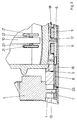
- the coaster is 1 hollow and houses a drive.
- This consists of a turntable 6 below the trough 3 and a drive pulley 7 in the lateral area of the Coaster 1 below the drive motor.
- Turntable 6 and drive pulley 7 are interconnected by means of a belt 8 coupled.
- On the top of the turntable 6 are several strong magnets 9 on a circle around the Axis of rotation arranged.
- the axis of rotation of the turntable 6 is located itself in the extension of a riser 10, the extends vertically and centrally through the beer barrel 2 and attached to a plug 11 in the top of the beer barrel 2 is in an opening 12 in the end cover 13 of the beer barrel 2 sits. Is on the connector plug 12 a tap 14 connected to the through the riser To be able to take 10 ascending beers from the beer barrel 2.
- the coaster 1 consists of a cup-shaped Cover 15, the underside of which is from a flat bottom 16 is closed.
- the turntable 6 and the drive disk 7 are in a space between the Cover 15 and the bottom 16.
- the turntable 6 is on one central, the riser 10 opposite bearing journal 17 rotatably mounted. Located near the journal 17 the magnets 9 in versions on the turntable 6, this in a flat recess 18 on the underside of the lid 15 run.
- the drive pulley 7 is directly perpendicular to the standing output shaft 19 placed. This protrudes an opening 20 in the lid 15, which is smaller than the housing the drive motor 5, but large enough to accommodate the Guide the output shaft 19 through the attached drive pulley 7 to be able to.
- the drive motor 5 is on the opening 20 set and closes this.
- the belt 8 around the turntable 6 and placed the drive pulley 7, which is now completely encapsulated is housed in the coaster 1.
- the stirring unit consists of two stirring bars 21, which are vertical aligned are attached to a ring 22, the is on a shoulder 23 on the riser 10, so that the stir bars 21 can rotate around the riser 10.
- the stirring bars 21 are made of a stainless steel coated Magnetic material manufactured. This will make them through taken the rotation of the turntable 6 and move on a circular path around the riser pipe 10.
- a stir bar 21 can be loosely placed on the floor of the beer keg 2. To the occurring The stirring rod can be used to prevent noise Be plastic coated. By rotating the turntable 6, this stir bar 21 moves in the beer barrel 2 rotationally.
- FIG. 2 also shows a sensor 24 from which an electrical line 25 to a controller 26 of the drive motor 5 leads. If you open a tap 14, see above the drive motor 5 is activated and the turntable 6 set in rotation so that the stirring unit responds and the suspended matter is whirled up in the drink.
Landscapes
- Chemical & Material Sciences (AREA)
- Chemical Kinetics & Catalysis (AREA)
- Table Equipment (AREA)
- Devices For Dispensing Beverages (AREA)
Abstract
Description
- Fig.1
- die Draufsicht auf einen Untersetzter mit einem aufgesetzten Bierfass,
- Fig.2
- einen Schnitt entlang der Linie II-II der Fig.1,
- Fig.3
- einen vergrößerten Ausschnitt aus Fig. 2 zur Verdeutlichung des Antriebs.
- 1
- Untersetzer
- 2
- Bierfass
- 3
- Mulde
- 4
- Seitenbereich
- 5
- Antriebsmotor
- 6
- Drehteller
- 7
- Antriebsscheibe
- 8
- Riemen
- 9
- Magnet
- 10
- Steigrohr
- 11
- Anschlussstopfen
- 12
- Öffnung
- 13
- Abschlussdeckel
- 14
- Zapfhahn
- 15
- Deckel
- 16
- Boden
- 17
- Lagerzapfen
- 18
- Ausnehmung
- 19
- Abtriebswelle
- 20
- Öffnung
- 21
- Rührstäbe
- 22
- Ring
- 23
- Absatz
- 24
- Sensor
- 25
- Leitung
- 26
- Steuerung
Claims (12)
- Zapfvorrichtung für Schwebstoffe enthaltende Getränke aus Behältnissen, insbesondere Hefeweizenbier aus einem Bierfass, dadurch gekennzeichnet, dass ein Rührwerk für das Behältnis (2) vorgesehen ist, welches einen Untersetzer (1) für das Behältnis (2) hat, in dem ein durch einen Antriebsmotor (5) in Rotation versetzbarer Magnet (9) vorgesehen ist, und dass dem Magnet (9) eine vor dem Füllen in das Behältnis (2) eingebrachter, von dem rotierenden Magneten (9) mitgenommener und in eine gleiche Rotation versetzbare Rühreinheit (21) zugeordnet ist.
- Zapfvorrichtung für Getränke nach Anspruch 1, dadurch gekennzeichnet, dass in dem Behältnis (2) ein Steigrohr (10) angeordnet ist und dass die Rühreinheit (21) drehbar am unteren Ende des Steigrohrs (10) befestigt ist.
- Zapfvorrichtung für Getränke nach Anspruch 1 oder 2, dadurch gekennzeichnet, dass ein oder mehrere Magnete (9) auf einem scheibenförmigen Drehteller (6) im Untersetzer (1) angeordnet sind.
- Zapfvorrichtung für Getränke nach Anspruch 3, dadurch gekennzeichnet, dass der Untersetzer (1) aus einem Boden (16) und einem Deckel (15) besteht, wobei das Behältnis (2) auf der Oberseite des Deckels (15) aufgesetzt ist, und dass der Drehteller (6) drehbar am Deckel (15) gehalten ist.
- Zapfvorrichtung für Getränke nach einem der vorhergehenden Ansprüche, dadurch gekennzeichnet, dass der Untersetzer (1) einen seitlich von der Aufstandsfläche für das Behältnis (2) abstehenden Bereich aufweist, auf dessen Oberseite der Antriebsmotor (5) befestigt ist.
- Zapfvorrichtung für Getränke nach Anspruch 5, dadurch gekennzeichnet, dass in dem seitliche Bereich des Untersetzer (1) eine Antriebsscheibe (7) untergebracht ist, deren Achse unmittelbar mit der Abtriebswelle (19) des Antriebsmotor (5) verbunden ist.
- Zapfvorrichtung für Getränke nach Anspruch 6, dadurch gekennzeichnet, dass der seitliche Bereich unterhalb des Antriebsmotor (5) eine Öffnung (20) aufweist, durch die die auf der Abtriebswelle (19) befestigte Antriebsscheibe (7) hindurchführbar ist.
- Zapfvorrichtung für Getränke nach Anspruch 5, 6 oder 7, dadurch gekennzeichnet, dass der Antrieb für den Drehteller (6) über einen Riemenantrieb erfolgt.
- Zapfvorrichtung für Getränke nach Anspruch 2, dadurch gekennzeichnet, dass das Rührwerk aus zwei senkrecht ausgerichteten Rührstäben (21) besteht, die an einem Ring (22) befestigt sind, der drehbar am Steigrohr (10) befestigt ist.
- Zapfvorrichtung für Getränke nach Anspruch 1, gekennzeichnet durch eine automatische Steuerung (26), welche den Antriebsmotor (5) betätigt, sobald ein Zapfhahn (14) der Zapfvorrichtung geöffnet wird.
- Zapfvorrichtung nach Anspruch 10, dadurch gekennzeichnet, dass die automatische Steuerung ein Halteglied aufweist, durch welches der Antriebsmotor (5) nach einem Öffnen des Zapfhahnes (14) eine vorgegebene Zeit eingeschaltet bleibt.
- Zapfvorrichtung nach Anspruch 1, dadurch gekennzeichnet, dass die Steuerung des Antriebsmotors (5) einen Zeitschalter zum periodischen Einschalten des Rührwerkes aufweist.
Applications Claiming Priority (4)
| Application Number | Priority Date | Filing Date | Title |
|---|---|---|---|
| DE10043602 | 2000-09-01 | ||
| DE10043602 | 2000-09-01 | ||
| DE10053640 | 2000-10-28 | ||
| DE10053640 | 2000-10-28 |
Publications (2)
| Publication Number | Publication Date |
|---|---|
| EP1184334A2 true EP1184334A2 (de) | 2002-03-06 |
| EP1184334A3 EP1184334A3 (de) | 2002-04-10 |
Family
ID=26006928
Family Applications (1)
| Application Number | Title | Priority Date | Filing Date |
|---|---|---|---|
| EP01119288A Withdrawn EP1184334A3 (de) | 2000-09-01 | 2001-08-10 | Zapfvorrichtung |
Country Status (1)
| Country | Link |
|---|---|
| EP (1) | EP1184334A3 (de) |
Cited By (1)
| Publication number | Priority date | Publication date | Assignee | Title |
|---|---|---|---|---|
| CN111804184A (zh) * | 2020-07-20 | 2020-10-23 | 吴院连 | 一种方便混药的药桶 |
Family Cites Families (3)
| Publication number | Priority date | Publication date | Assignee | Title |
|---|---|---|---|---|
| GB776522A (en) * | 1955-11-01 | 1957-06-05 | William Harrison Jacobs | Improvements in beverage dispenser |
| DE3439654C2 (de) * | 1984-10-30 | 1987-02-26 | Brauerei Beck GmbH & Co, 2800 Bremen | Vorrichtung zum gleichmäßigen Verteilen von Hefeteilchen in hefehaltigem Bier |
| DE8531615U1 (de) * | 1985-11-08 | 1986-04-03 | Lich-Gömmer, Ingeborg, 6300 Gießen | Systembehälter für Getränke-Dispenser mit aufsetzbarer Rühreinrichtung |
-
2001
- 2001-08-10 EP EP01119288A patent/EP1184334A3/de not_active Withdrawn
Cited By (1)
| Publication number | Priority date | Publication date | Assignee | Title |
|---|---|---|---|---|
| CN111804184A (zh) * | 2020-07-20 | 2020-10-23 | 吴院连 | 一种方便混药的药桶 |
Also Published As
| Publication number | Publication date |
|---|---|
| EP1184334A3 (de) | 2002-04-10 |
Similar Documents
| Publication | Publication Date | Title |
|---|---|---|
| DE69608622T2 (de) | Plattformrüttler mit dreidimensionaler bewegung | |
| DE60030310T2 (de) | Mix- und giessapparat mit drehbarem arm und zugehörigem gefäss | |
| EP1287878B1 (de) | Vorrichtung zur Bearbeitung von Materialien | |
| DE2304395A1 (de) | Zentrifuge mit automatisch einstellbaren rohrhaltern | |
| WO1997025911A1 (de) | Rühreinrichtung | |
| DE1598369A1 (de) | Zentrifuge zum Mischen und Dekantieren,insbesondere zur Blutprobenuntersuchung | |
| CH698173B1 (de) | Behälter-Verschluss zum gleichzeitigen Ausgiessen zweier separater Flüssigkeiten in einem bestimmten Mengenverhältnis. | |
| DE723690T1 (de) | Münzspeicher und -ausgabevorrichtung | |
| DE2428615A1 (de) | Mischer | |
| DE3526690A1 (de) | Automat zur ausgabe von bechern mit frisch gemachten getraenken | |
| EP1184334A2 (de) | Zapfvorrichtung | |
| CH680164A5 (de) | ||
| DE3706002C2 (de) | Vorrichtung zum Zerkleinern, Mischen, Kneten und Schlagen von Gut | |
| DE69903021T2 (de) | Mühle zur zerkleinerung von schüttgut | |
| EP0164303A2 (de) | Rührwerk zum Suspendieren von Feststoffen und Flüssigkeiten | |
| DE3439654C2 (de) | Vorrichtung zum gleichmäßigen Verteilen von Hefeteilchen in hefehaltigem Bier | |
| EP0019052B1 (de) | Vorrichtung zum Entnehmen von Proben aus zähflüssigen Kunstharzen aus einem Behälter | |
| DE2028620A1 (de) | Behälter mit Rührwerk für Flüssigkeiten | |
| DE68908228T2 (de) | Vorrichtung zur Abgabe von Bier und anderen Getränken. | |
| DE2224571A1 (de) | Vorrichtung und Verfahren zum Bewirken von Kontakt zwischen Gas und Flüssigkeit | |
| DE4142967A1 (de) | Bioreaktor | |
| DE3043542C2 (de) | ||
| DE102007058046A1 (de) | Vorrichtung zum Behandeln von Flaschen oder dergleichen Behälter, insbesondere Füllmaschine | |
| DE2314824A1 (de) | Geraet fuer die durchmischung von fluessigkeiten | |
| EP0203316B1 (de) | Verfahren und Vorrichtung zum Abscheiden von Metallen und von anderen Feststoffen aus Flüssigkeiten |
Legal Events
| Date | Code | Title | Description |
|---|---|---|---|
| PUAI | Public reference made under article 153(3) epc to a published international application that has entered the european phase |
Free format text: ORIGINAL CODE: 0009012 |
|
| PUAL | Search report despatched |
Free format text: ORIGINAL CODE: 0009013 |
|
| AK | Designated contracting states |
Kind code of ref document: A2 Designated state(s): AT BE CH CY DE DK ES FI FR GB GR IE IT LI LU MC NL PT SE TR |
|
| AX | Request for extension of the european patent |
Free format text: AL;LT;LV;MK;RO;SI |
|
| AK | Designated contracting states |
Kind code of ref document: A3 Designated state(s): AT BE CH CY DE DK ES FI FR GB GR IE IT LI LU MC NL PT SE TR |
|
| AX | Request for extension of the european patent |
Free format text: AL;LT;LV;MK;RO;SI |
|
| 17P | Request for examination filed |
Effective date: 20021009 |
|
| AKX | Designation fees paid |
Free format text: AT BE CH CY DE DK ES FI FR GB GR IE IT LI LU MC NL PT SE TR |
|
| 17Q | First examination report despatched |
Effective date: 20021210 |
|
| GRAP | Despatch of communication of intention to grant a patent |
Free format text: ORIGINAL CODE: EPIDOSNIGR1 |
|
| STAA | Information on the status of an ep patent application or granted ep patent |
Free format text: STATUS: THE APPLICATION IS DEEMED TO BE WITHDRAWN |
|
| 18D | Application deemed to be withdrawn |
Effective date: 20040630 |