EP1184850A2 - Aufzeichnungs- und/oder Wiedergabegerät und Aufzeichnungs- und/oder Wiedergabeverfahren, welches es ermöglicht ein auf einem Steg positioniertes, Vorsatzloch auf einer Platte mit hoher Präzision sicher zu detektieren - Google Patents
Aufzeichnungs- und/oder Wiedergabegerät und Aufzeichnungs- und/oder Wiedergabeverfahren, welches es ermöglicht ein auf einem Steg positioniertes, Vorsatzloch auf einer Platte mit hoher Präzision sicher zu detektieren Download PDFInfo
- Publication number
- EP1184850A2 EP1184850A2 EP01117795A EP01117795A EP1184850A2 EP 1184850 A2 EP1184850 A2 EP 1184850A2 EP 01117795 A EP01117795 A EP 01117795A EP 01117795 A EP01117795 A EP 01117795A EP 1184850 A2 EP1184850 A2 EP 1184850A2
- Authority
- EP
- European Patent Office
- Prior art keywords
- signal
- land pre
- pit
- wobbling
- amplitude
- Prior art date
- Legal status (The legal status is an assumption and is not a legal conclusion. Google has not performed a legal analysis and makes no representation as to the accuracy of the status listed.)
- Withdrawn
Links
Images


Classifications
-
- G—PHYSICS
- G11—INFORMATION STORAGE
- G11B—INFORMATION STORAGE BASED ON RELATIVE MOVEMENT BETWEEN RECORD CARRIER AND TRANSDUCER
- G11B7/00—Recording or reproducing by optical means, e.g. recording using a thermal beam of optical radiation by modifying optical properties or the physical structure, reproducing using an optical beam at lower power by sensing optical properties; Record carriers therefor
- G11B7/004—Recording, reproducing or erasing methods; Read, write or erase circuits therefor
- G11B7/005—Reproducing
-
- G—PHYSICS
- G11—INFORMATION STORAGE
- G11B—INFORMATION STORAGE BASED ON RELATIVE MOVEMENT BETWEEN RECORD CARRIER AND TRANSDUCER
- G11B7/00—Recording or reproducing by optical means, e.g. recording using a thermal beam of optical radiation by modifying optical properties or the physical structure, reproducing using an optical beam at lower power by sensing optical properties; Record carriers therefor
- G11B7/007—Arrangement of the information on the record carrier, e.g. form of tracks, actual track shape, e.g. wobbled, or cross-section, e.g. v-shaped; Sequential information structures, e.g. sectoring or header formats within a track
- G11B7/00745—Sectoring or header formats within a track
-
- G—PHYSICS
- G11—INFORMATION STORAGE
- G11B—INFORMATION STORAGE BASED ON RELATIVE MOVEMENT BETWEEN RECORD CARRIER AND TRANSDUCER
- G11B7/00—Recording or reproducing by optical means, e.g. recording using a thermal beam of optical radiation by modifying optical properties or the physical structure, reproducing using an optical beam at lower power by sensing optical properties; Record carriers therefor
- G11B7/08—Disposition or mounting of heads or light sources relatively to record carriers
- G11B7/09—Disposition or mounting of heads or light sources relatively to record carriers with provision for moving the light beam or focus plane for the purpose of maintaining alignment of the light beam relative to the record carrier during transducing operation, e.g. to compensate for surface irregularities of the latter or for track following
- G11B7/0901—Disposition or mounting of heads or light sources relatively to record carriers with provision for moving the light beam or focus plane for the purpose of maintaining alignment of the light beam relative to the record carrier during transducing operation, e.g. to compensate for surface irregularities of the latter or for track following for track following only
Definitions
- the present invention relates to a recording and/or reproducing apparatus and a recording and/or reproducing method, which can be applied preferably to a DVD reproducing apparatus, a DVD recording apparatus and a DVD recording and/or reproducing apparatus and the like for recording and/or reproducing in/from an optical disc such as DVD-R and DVD-RW.
- address information and the like is preliminarily recorded in a recordable optical recording medium so as to enable recording of desired information, and a recording track wobbled under a predetermined frequency is provided to generate a clock signal for use in recording and/or reproducing operation.
- DVD-R digital versatile disc-recordable
- CD compact disc
- DVD-R digital versatile disc-recordable
- information such as video data and audio data is recorded in concave pre-grooves in the form of a recording pit, while address information and the like are preliminarily recorded in convex land located between these pre-grooves in the form of land pre-pit (LPP).
- LPP land pre-pit
- the land pre-pits (LPP) on the land are recorded such that a LPP do not overlap with an adjacent land pre-pit (LPP) located beyond a pre-groove on a straight line perpendicular to a tangent line of the pre-groove.
- the pre-groove is employed for rotation control of the DVD-R and provided so as to be wobbled slightly in a radius direction at a predetermined frequency based on the reference clock.
- the wobbling frequency is detected from a reproduction output of the wobbled pre-groove (hereinafter referred to as wobbling groove) and then feedback control is carried out so that this detected wobbling frequency coincides with the frequency of the reference clock.
- a reflection light of light beam (laser beam) irradiated to the wobbling groove from a semiconductor laser is received by a photo detector divided to at least two sections with optically parallel lines in the tangent line direction of the wobbling groove and then, a differential signal in a direction perpendicular to the wobbling groove between the output signals sent from respective regions (individual divided regions) of this photo detector is obtained. Then, by comparing this differential signal with a predetermined threshold value and then binarizing, its binary signal is detected.
- the dividing regions are formed on the photo detector in the radius direction of the optical disc with the aforementioned dividing lines and the differential signal is called radial push-pull signal.
- the land pre-pit (LPP) can be detected with such binarized binary signal by comparing the radial push-pull signal (differential signal) with the predetermined threshold value is that as described above, the land pre-pits (LPP) are formed such that there are no two adjacent land pre-pits beyond a wobbling groove on a straight line perpendicular to the tangent line of the wobbling groove.
- the reflection light from the lands on both sides do not contain the land pre-pit (LPP) reflection components at the same time (only the reflection light from either land contains the LPP component).
- LPP land pre-pit
- the binary signal obtained by comparing only one of the both polarity components (for example, positive polarity component) obtained by the above computation of the differential with the predetermined threshold value is employed as the land pre-pit signal (LPP signal).
- the land pre-pit (LPP) is detected by comparing the radial push-pull signal (differential signal) with the predetermined threshold and then binarizing its result.
- two input signals are adjusted so as to be equal in terms of the amplitude ratio for computation of the radial push-pull signal (differential signal), laser power modulation component during recording turns to noise in the land pre-pit (LPP) according to this method.
- the land pre-pit (LPP) is detected erroneously due to an influence of the recording pit.
- the balance of the radial push-pull signal is destroyed, so that the radial push-pull signal may be detected erroneously either.
- an object of the invention is to provide a recording and/or reproducing apparatus and a recording and/or reproducing method for extracting the radial pre-pit signal (LPP signal) at a high precision with a simple structure.
- a recording and/or reproducing apparatus for recording and/or reproducing information signal into/from a disc-like recording medium including wobbling grooves each wobbled according to a predetermined frequency and serving as a recording track for the information signal and lands in which at least address information is preliminarily recorded in the form of a land pre-pit at a predetermined wobbling cycle interval, the wobbling grooves and the lands being formed alternately spirally or coaxially
- the recording and/or reproducing apparatus comprising: coefficient multiplying means for when a light beam is irradiated to the disk-like recording medium, receiving reflection light from the disk-like recording medium with first and second light receiving regions, divided equally along the recording track of the disk-like recording medium and multiplying one of respective light reception outputs of the first and second light receiving regions with a predetermined coefficient k ; push-pull signal generation means for outputting a differential as a radial push-pull signal, the differential being produced by subtracting the multiplication processing result output
- a recording and/or reproducing apparatus for recording and/or reproducing information signal into/from a disc-like recording medium including wobbling grooves each wobbled according to a predetermined frequency and serving as a recording track for the information signal and lands in which at least address information is preliminarily recorded in the form of a land pre-pit at a predetermined wobbling cycle interval, the wobbling grooves and the lands being formed alternately spirally or coaxially
- the recording and/or reproducing apparatus comprising: coefficient multiplying means for when light beam is irradiated to the disk-like recording medium, receiving reflection light from the disk-like recording medium with first and second light receiving regions, divided equally along the recording track of the disk-like recording medium and multiplying one of respective light reception outputs of the first and second light receiving regions with a predetermined coefficient k ; push-pull signal generation means for outputting a differential as a radial push-pull signal, the differential being produced by subtracting the multiplication processing result output
- a recording and/or reproducing apparatus for recording and/or reproducing information signal into/from a disc-like recording medium including wobbling grooves each wobbled according to a predetermined frequency and serving as a recording track for the information signal and lands in which at least address information is preliminarily recorded in the form of a land pre-pit at a predetermined wobbling cycle interval, the wobbling grooves and the lands being formed alternately spirally or coaxially
- the recording and/or reproducing apparatus comprising: coefficient multiplying means for when a light beam is irradiated to the disk-like recording medium, receiving reflection light from the disk-like recording medium with first and second light receiving regions, divided equally along the recording track of the disk-like recording medium and multiplying one of respective light reception outputs of the first and second light receiving regions with a predetermined coefficient k ; push-pull signal generation means for outputting a differential as a radial push-pull signal, the differential being produced by subtracting the multiplication processing result output
- a recording and/or reproducing apparatus for recording and/or reproducing information signal into/from a disc-like recording medium including wobbling grooves each wobbled according to a predetermined frequency and serving as a recording track for the information signal and lands in which at least address information is preliminarily recorded in the form of a land pre-pit at a predetermined wobbling cycle interval, the wobbling grooves and the lands being formed alternately spirally or coaxially
- the recording and/or reproducing apparatus comprising: coefficient multiplying means for when a light beam is irradiated to the disk-like recording medium, receiving reflection light from the disk-like recording medium with first and second light receiving regions, divided equally along the recording track of the disk-like recording medium and multiplying one of respective light reception outputs of the first and second light receiving regions with a predetermined coefficient 1/k1; push-pull signal generation means for outputting a differential as a radial push-pull signal, the differential being produced by subtracting the other of the respective
- a recording and/or reproducing apparatus for recording and/or reproducing information signal into/from a disc-like recording medium including wobbling grooves each wobbled according to a predetermined frequency and serving as a recording track for the information signal and lands in which at least address information is preliminarily recorded in the form of a land pre-pit at a predetermined wobbling cycle interval, the wobbling grooves and the lands being formed alternately spirally or coaxially
- the recording and/or reproducing apparatus comprising: first coefficient multiplying means for when a light beam is irradiated to the disk-like recording medium, receiving reflection light from the disk-like recording medium with first and second light receiving regions, divided equally along the recording track of the disk-like recording medium and multiplying one of respective light reception outputs of the first and second light receiving regions with a predetermined coefficient 1/k3; second coefficient multiplying means for multiplying the other of the respective light reception outputs of said first and second light receiving regions with a predetermined coefficient k3; push
- a recording and/or reproducing apparatus for recording and/or reproducing information signal into/from a disc-like recording medium including wobbling grooves each wobbled according to a predetermined frequency and serving as a recording track for the information signal and lands in which at least address information is preliminarily recorded in the form of a land pre-pit at a predetermined wobbling cycle interval, the wobbling grooves and the lands being formed alternately spirally or coaxially
- the recording and/or reproducing apparatus comprising: first coefficient multiplying means for when a light beam is irradiated to the disk-like recording medium, receiving reflection light from the disk-like recording medium with first and second light receiving regions, divided equally along the recording track of the disk-like recording medium and multiplying one of respective light reception outputs of the first and second light receiving regions with a predetermined coefficient 1/k3; second coefficient multiplying means for multiplying the other of the respective light reception outputs of the first and second light receiving regions with a predetermined coefficient k3; push
- a recording and/or reproducing method for recording and/or reproducing information signal into/from a disc-like recording medium including wobbling grooves each wobbled according to a predetermined frequency and serving as a recording track for the information signal and lands in which at least address information is preliminarily recorded in the form of a land pre-pit at a predetermined wobbling cycle interval, the wobbling grooves and the lands being formed alternately spirally or coaxially, the recording and/or reproducing method comprising the steps of: when a light beam is irradiated to the disk-like recording medium, receiving reflection light from the disk-like recording medium with first and second light receiving regions, divided equally along the recording track of the disk-like recording medium and multiplying one of respective light reception outputs of said first and second light receiving regions with a predetermined coefficient k ; outputting a differential as a radial push-pull signal, the differential being produced by subtracting the multiplication processing result outputted at the coefficient multiplying step from
- a recording and/or reproducing method for recording and/or reproducing information signal into/from a disc-like recording medium including wobbling grooves each wobbled according to a predetermined frequency and serving as a recording track for the information signal and lands in which at least address information is preliminarily recorded in the form of a land pre-pit at a predetermined wobbling cycle interval, the wobbling grooves and the lands being formed alternately spirally or coaxially, the recording and/or reproducing method comprising the steps of: when a light beam is irradiated to the disk-like recording medium, receiving reflection light from the disk-like recording medium with first and second light receiving regions, divided equally along the recording track of the disk-like recording medium and multiplying one of respective light reception outputs of the first and second light receiving regions with a predetermined coefficient k ; outputting a differential as a radial push-pull signal, the differential being produced by subtracting the multiplication processing result outputted at the coefficient multiplying step from
- a recording and/or reproducing method for recording and/or reproducing information signal into/from a disc-like recording medium including wobbling grooves each wobbled according to a predetermined frequency and serving as a recording track for the information signal and lands in which at least address information is preliminarily recorded in the form of a land pre-pit at a predetermined wobbling cycle interval, the wobbling grooves and the lands being formed alternately spirally or coaxially, the recording and/or reproducing method comprising the steps of: when a light beam is irradiated to the disk-like recording medium, receiving reflection light from the disk-like recording medium with first and second light receiving regions, divided equally along the recording track of the disk-like recording medium and multiplying one of respective light reception outputs of the first and second light receiving regions with a predetermined coefficient k ; outputting a differential as a radial push-pull signal, the differential being produced by subtracting the multiplication processing result outputted at the coefficient multiplying step from
- a recording and/or reproducing method for recording and/or reproducing information signal into/from a disc-like recording medium including wobbling grooves each wobbled according to a predetermined frequency and serving as a recording track for the information signal and lands in which at least address information is preliminarily recorded in the form of a land pre-pit at a predetermined wobbling cycle interval, the wobbling grooves and the lands being formed alternately spirally or coaxially, the recording and/or reproducing method comprising the steps of: when a light beam is irradiated to the disk-like recording medium, receiving reflection light from the disk-like recording medium with first and second light receiving regions, divided equally along the recording track of the disk-like recording medium and multiplying one of respective light reception outputs of the first and second light receiving regions with a predetermined coefficient k ; outputting a differential as a radial push-pull signal, the differential being produced by subtracting the multiplication processing result outputted at the coefficient multiplying step from
- a recording and/or reproducing method for recording and/or reproducing information signal into/from a disc-like recording medium including wobbling grooves each wobbled according to a predetermined frequency and serving as a recording track for the information signal and lands in which at least address information is preliminarily recorded in the form of a land pre-pit at a predetermined wobbling cycle interval, the wobbling grooves and the lands being formed alternately spirally or coaxially, the recording and/or reproducing method comprising the steps of: when a light beam is irradiated to the disk-like recording medium, receiving reflection light from the disk-like recording medium with first and second light receiving regions, divided equally along the recording track of the disk-like recording medium and multiplying one of respective light reception outputs of the first and second light receiving regions with a predetermined coefficient 1/k1; outputting a differential as a radial push-pull signal, the differential being produced by subtracting the other of the respective light reception outputs of the first and
- a recording and/or reproducing method for recording and/or reproducing information signal into/from a disc-like recording medium including wobbling grooves each wobbled according to a predetermined frequency and serving as a recording track for the information signal and lands in which at least address information is preliminarily recorded in the form of a land pre-pit at a predetermined wobbling cycle interval, the wobbling grooves and the lands being formed alternately spirally or coaxially, the recording and/or reproducing method comprising the steps of: when a light beam is irradiated to the disk-like recording medium, receiving reflection light from said disk-like recording medium with first and second light receiving regions, divided equally along the recording track of the disk-like recording medium and multiplying one of respective light reception outputs of the first and second light receiving regions with a predetermined coefficient 1/k1; outputting a differential as a radial push-pull signal, the differential being produced by subtracting the other of the respective light reception outputs of the first and
- a recording and/or reproducing method for recording and/or reproducing information signal into/from a disc-like recording medium including wobbling grooves each wobbled according to a predetermined frequency and serving as a recording track for the information signal and lands in which at least address information is preliminarily recorded in the form of a land pre-pit at a predetermined wobbling cycle interval, said wobbling grooves and said lands being formed alternately spirally or coaxially, the recording and/or reproducing method comprising: when a light beam is irradiated to the disk-like recording medium, receiving reflection light from the disk-like recording medium with first and second light receiving regions, divided equally along the recording track of the disk-like recording medium and multiplying one of respective light reception outputs of the first and second light receiving regions with a predetermined coefficient 1/k3; multiplying the other of the respective light reception outputs of the first and second light receiving regions with a predetermined coefficient k3; outputting a differential as a radial
- a recording and/or reproducing method for recording and/or reproducing information signal into/from a disc-like recording medium including wobbling grooves each wobbled according to a predetermined frequency and serving as a recording track for the information signal and lands in which at least address information is preliminarily recorded in the form of a land pre-pit at a predetermined wobbling cycle interval, the wobbling grooves and the lands being formed alternately spirally or coaxially, the recording and/or reproducing method comprising the steps of: when a light beam is irradiated to the disk-like recording medium, receiving reflection light from the disk-like recording medium with first and second light receiving regions, divided equally along the recording track of the disk-like recording medium and multiplying one of respective light reception outputs of the first and second light receiving regions with a predetermined coefficient 1/k3; multiplying the other of the respective light reception outputs of the first and second light receiving regions with a predetermined coefficient k3; outputting a differential as a
- the recording and/or reproducing apparatus and the recording and/or reproducing method of the present invention can be applied to a disc recording and/or reproducing apparatus, which records in/reproduces from a DVD-R, DVD-RW (hereinafter referred to as DVD).
- DVD a DVD-R, DVD-RW
- concave wobbling grooves 32 and convex lands 33 are formed in a surface of a disc-like transparent substrate K alternately in a spiral or concentric form by injection molding.
- Pigment film 35 is formed on the wobbling groove 32 and the land 33 as a data-recording layer.
- Recording light beam BM modulated corresponding to data, which should be recorded in the pigment film 35, (hereinafter referred to as recording data) is irradiated from the side of the other face so that pit string corresponding to the recording data is formed irreversibly.
- the optical disk is a write-once one.
- This DVD 31 has a wobbling groove 32, which is wobbled corresponding to the wobbling signal containing predetermined frequency components and this wobbling groove 32 serves as a data recording track for recording the aforementioned recording data.
- the land pre-pits 34 in which for example, address information (absolute position information) or the like on an optical disc face is recorded at a predetermined wobbling cycle interval, are preliminarily formed in the land 33 between the adjacent wobbling grooves 32.
- Gold deposited film 36 is formed on the pigment film 35.
- reproduction light beam BM irradiated to the data recording track is reflected by this gold deposited film 36 at a high reflectance.
- protective film 37 is formed on the gold deposited film 36.
- wobbling frequency of the wobbling groove 32 provided as the data recording track is detected, so that the DVD 31 is driven based on this wobbling frequency. Further, the address information and the like are detected from the land pre-pit 34 and a recording position is detected based on this address information so as to achieve recording or reproduction of the recording data in/from the wobbling groove 32.
- recording light beam BM modulated corresponding to recording data is irradiated such that the center of a light spot coincides with the center of the wobbling groove 32. Consequently, a pit string corresponding to the recording data is formed on a data-recording track on the wobbling groove 32 so as to record the recording data.
- the size of a light spot SP of the recording light beam BM is set up so that part thereof is irradiated on not only the wobbling groove 32 but also on the land 33 between the adjacent wobbling grooves 32.
- a photo detector which is divided by dividing lines optically parallel to a tangent line of the wobbling groove 32 or a rotation direction of the DVD 31. Based on an output of this photo detector, for example, a push-pull signal is formed so as to apply tracking servo. Further, a wobbling signal of the wobbling groove 32 is extracted from a photo detector and then, based on a wobbling pulse generated by binarizing this wobbling signal, a recording clock synchronous with a rotation of the DVD 31 is formed.
- Fig. 2 its upper portion indicates a recording format for the recording data while the waveform of its lower portion indicates wobbling state (meandering state recognized when the wobbling groove 32 is viewed along the normal line with respect to a substrate face) of the wobbling groove 32, which intends to record the recording data.
- Upward arrows between the upper portion indicating the recording format for the recording data and the lower portion indicating the wobbling state of the wobbling groove 32 shows schematically positions in which the land pre-pits 34 are to be formed.
- the wobbling state of the wobbling groove 32 in Fig.2 is expressed with an amplitude larger than an actual amplitude to facilitate understanding.
- the recording data is recorded on the centerline of the wobbling groove 32 as described above.
- the recording data which is to be recorded in the DVD 31, is preliminary divided for each synch frame as an information unit.
- a single recording sector is comprised of 26 synch frames.
- a single error correcting code (ECC) is comprised of 16 recording sectors.
- a synch frame has a length of 1488 times (1488 T) the unit length T corresponding to a pit interval specified by the recording format upon recording the recording data.
- Synchronous information SY for obtaining synchronism of each synch frame is recorded in a portion corresponding to the length of 14T at the head of a synch frame.
- the address information (land pre-pit 34) to be recorded in the DVD 31 is recorded preliminarily in each synch frame of the recording data upon manufacturing of an optical disc.
- a land pre-pit 34 (land pre-pit B0) indicated with an arrow B0 in the same Figure is formed on the land 33 adjacent to a region in which the synchronous information SY of each synch frame of the recording data is recorded in order to indicate the synchronous information of the address information
- both or one of land pre-pits 34 (land pre-pit B1, land pre-pit B2) indicated with arrows B1, B2 in Fig.2 is formed on the land 33 adjacent to a front half portion excluding the region in which the synchronous information SY in the synch frame is recorded, in order to indicate the content of the address information to be recorded.
- the land pre-pit B1 or the land pre-pit B2 may not be formed depending on the content of the address information to be recorded.
- the land pre-pit 34 is formed in every other synch frame in a recording sector to record the address information and the like.
- EVEN frame and ODD frame are repeated alternately.
- the land pre-pits 34 are formed in the EVEN frame as indicated by the upward arrows of solid line in Fig.2, no land pre-pit 34 is formed in the ODD frame.
- the land pre-pit 34 is formed in the EVEN frame, all the land pre-pits including the land pre-pit B0, land pre-pit B1 and land pre-pit B2 are formed in a synch frame at the head of the recording sector. If the address information to be recorded in the synch frame is "1" in a synch frame other than the head of the recording sector, only the land pre-pit B0 and land pre-pit B2 are formed. If the address information is "0", only the land pre-pit B0 and the land pre-pit B1 are formed.
- the land pre-pit 34 is formed in the ODD frame, only the land pre-pit B0 and the land pre-pit B1 are formed in a synch frame at the head of the recording sector while the portion other than the head of the recording sector is the same as the aforementioned EVEN frame.
- the land pre-pit 34 should be formed in the EVEN frame or the ODD frame is determined depending on the position of the land pre-pit 34 formed on the adjacent land 33 ahead.
- the land pre-pit 34 is formed in the EVEN frame. If the land pre-pit 34 to be formed in the EVEN frame overlaps the land pre-pit 34 on the adjacent land 33 precedingly generated in the diameter direction, this land pre-pit 34 is formed in the ODD frame.
- a land pre-pit 34 is formed such that it does not overlap with another on the adjacent land 33 in the diameter direction of the DVD 31 as shown in Fig. 3. If the land pre-pit 34 is formed in this manner, it does not comes that a land pre-pit 34 on a land 33 and a land pre-pit 34 on the adjacent land 33 are overlapped with each other in the diameter direction of the DVD 31. Consequently, upon detecting the land pre-pit 34, an influence by land pre-pit cross talk on an adjacent land can be reduced.
- a synch frame whose head is expressed with a black belt on the land 33 is a synch frame in which the land pre-pit 34 is formed, while a synch frame whose head is expressed with a blank belt is a synch frame in which the land pre-pit 34 is not formed.
- the wobbling grooves 32 are wobbled at a constant wobbling frequency f0 (frequency allowing wobbling signals of wobble eight cycles to be contained in a synch frame) over the entire synch frames.
- a signal for controlling a rotation of the DVD 31 is detected and a recording clock is generated.
- the land pre-pits B0 to B2 are formed preliminarily upon manufacturing an optical disc, so that the land pre-pits B1 and the land pre-pit B2 are formed preliminarily apart by 186T (1488T/8) each from the land pre-pit B0.
- the land pre-pit 34 is formed on the land 33 of every other synch frame as described above, such that it does not overlap, in the diameter direction of the DVD 31, with another on the adjacent land 33. Therefore, the landpre-pit 34 appears at every 16 wobble cycles of the wobbling groove 32 in two lands 33 adjacent a wobbling groove 32 and further, the land pre-pit 34 appears alternately on both sides of the wobbling groove 32.
- Fig.4 is a block diagram of a disc recording and/or reproducing apparatus of the first embodiment.
- the disc recording and/or reproducing apparatus of the first embodiment comprises an optical pickup 2 for recording and/or reproducing data by irradiating light beam from a semiconductor laser (not shown) to the DVD 31 through an objective lens (not shown) and a preamplifier 3, which amplifies a reproduction output from the optical pickup 2 and outputs it.
- Fig.5A is a schematic diagram showing a state in which the photo detector (PD) in the optical pickup 2 is located in the center of the wobbling groove 32 and the land pre-pit 34 on the land 33 on the right of the same Figure is being detected by this photo detector (PD).
- the aforementioned photo detector PD is formed in a substantially rectangular form and its entire light-receiving region is divided equally to four sections with a straight line along the diameter direction of the DVD 31 and a line along the track direction.
- the light spot SP focused on this photo detector PD is comprised of two pairs, which are a combination of a light receiving region A and a light receiving region B located on the outer side with respect to the DVD 31 and a combination of a light receiving region C and a light receiving region D located on the inner side, so that it is divided to two sections with respect to a straight line along the direction of the recording track of the DVD 31.
- (A+B) signal obtained by summing up light reception signals from the two light receiving regions A and B on the outer side of the DVD 31 and (C+D) signal obtained by summing up light reception signals from the two light receiving regions C and D on the inner side of the DVD 31 are outputted.
- brightnesses on the outer side and inner side of the DVD 31 are unbalanced due to an influence by refraction of the light beam BM to the land pre-pit 34 on the photo detector PD.
- the (A+B) signal and the (C+D) signal are outputted as one is a turned-over type of the other on the side above 0 level.
- the output amplitude of the (A+B) signal and the output amplitude of the (C+D) signal be substantially of the same level. If both the signals are not substantially the same level due to adjustment condition of the optical pickup or the like, the (A+B) adding circuit 4 and the (C+D) adding circuit 5 only have to be adjusted with an appropriate adjusting circuit, so that output amplitudes of both are substantially of the same level, before a differential signal is produced with a RPP generation circuit 8, which will be described later.
- a multiplication processing of multiplying a predetermined coefficient k with minus sign has to be carried out only on the signal (A+B) including the land pre-pit signal (LPP signal) directed to 0 level (directed downward) with respect to the wobbling signal (WBL signal). If the (C+D) includes the land pre-pit signal (LPP signal) directed downward, different from shown here, the (C+D) may be subjected to multiplication processing. However, this determination of which signal is subjected to the multiplication processing does not have to be carried out within the apparatus and further, which should be subjected to the multiplication processing can be set up preliminarily. Thus, it is permissible to connect a coefficient multiplying circuit 6 to the (A+B) adding circuit 4 side as indicated in this embodiment.
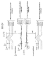
- the disc recording and/or reproducing apparatus comprises the (A+B) adding circuit 4 for detecting the (A+B) signal obtained by summing the light reception signals from the two light receiving regions A and B on the outer side of the DVD 31 and a (C+D) adding circuit 5 for detecting the (C+D) signal obtained by summing the reception signals from the two light receiving regions C and D on the inner side of the DVD 31.
- the disc recording and/or reproducing apparatus contains a coefficient multiplying circuit 6, which inverts the polarity of the (A+B) signal from the (A+B) adding circuit 4 and multiplies with a predetermined coefficient k so as to output ⁇ -k(A+B) ⁇ .
- the detection accuracy of the land pre-pit (LPP) on the optical disc is improved.
- the disc recording and/or reproducing apparatus comprises a RPP generation circuit 8 for generating the radial push-pull signal ⁇ (C+D)-k(A+B) ⁇ based on the (C+D) signal and the ⁇ -k(A+B) ⁇ signal, a binarizing circuit 9 for binarizing the land pre-pit signal (LPP signal) contained in the radial push-pull signal from the RPP generation circuit 8, a LPP decoding circuit 10 for decoding address information and the like of the land pre-pit signal (LPP signal) binarized by the binarizing circuit 9 and a CPU 11 which computes an error rate of the land pre-pit signal decoded by the LPP decoding circuit 10 and outputting the error rate.
- a RPP generation circuit 8 for generating the radial push-pull signal ⁇ (C+D)-k(A+B) ⁇ based on the (C+D) signal and the ⁇ -k(A+B) ⁇ signal
- a binarizing circuit 9 for binarizing
- the disc recording and/or reproducing apparatus comprises an RF circuit 7 for generating a sum signal ⁇ RF signal: (A+B+C+D) ⁇ by summing up the (A+B) signal from the (A+B) adding circuit 4 and the (C+D) signal from the (C+D) adding circuit 5, an LPP amplitude detecting circuit (land pre-pit signal amplitude detecting circuit) 12, which extracts a land pre-pit signal (LPP signal) from the radial push-pull signal sent from the RPP generation circuit 8, detects the amplitude of this land pre-pit signal and outputs its result to an LPPb generation circuit 14 and a coefficient setting circuit 16, and a WBL amplitude detecting circuit (wobbling signal amplitude detecting circuit) 13, which extracts a wobbling signal (WBL signal) of the recording track from the radial push-pull signals sent from the RPP generation circuit 8, detects the amplitude of this wobbling signal and outputs its result to a WBLb generation circuit 15
- this disc recording and/or reproducing apparatus comprises the LPPb generation circuit (normalization land pre-pit signal amplitude detecting circuit) 14, which outputs the level of a land pre-pit signal (LPP signal) extracted by the LPP amplitude detecting circuit 12 as a land pre-pit signal (hereinafter referred to as LPPb signal) normalized with respect to the level of a sum signal (A+B+C+D) generated by the RF circuit 7, the WBLb generation circuit (normalized wobbling signal amplitude detecting circuit) 15, which outputs the level of a wobbling signal extracted by the WBL amplitude detecting circuit 13 as a wobbling signal (hereinafter referred to as WBLb signal) normalized with respect to the level of the sum signal (A+B+C+D) generated by the RF circuit 7 and a lens shift amount detecting circuit 17, which detects a lens shift amount in the radial direction from the center of optical axis of an objective lens in the optical pickup 2 and outputs the lens shift amount.
- the disc recording and/or reproducing apparatus comprises the coefficient setting circuit 16 for setting the predetermined coefficient k of the coefficient multiplying circuit 6 depending on the error rate from the CPU 11 upon detecting the land pre-pit signal, the amplitude of a land pre-pit signal from the LPP amplitude detecting circuit 12, the amplitude of a wobbling signal from the WBL amplitude detecting circuit 13, the normalized LPPb signal from the LPPb generation circuit 14, the normalized WBLb signal from the WBLb generation circuit 15 and the lens shift amount detected by the lens shift amount detecting circuit 17.
- LPP landpre-pit
- the wobbling signal and LPP signal are expressed with a straight line approximately as is different from Figs.12, 13 because they are expressed only in a simplified way.
- the present invention includes reproducing a non-recording portion and thus measuring a related basic parameter about that disc. Because in an actual recording and/or reproducing apparatus, the non-recording region on the disc can be recognized, it is possible to seek that region so as to obtain the aforementioned parameter.
- a read-in region on the most inside periphery of the disc and a read-out region on the most outer periphery of the disc are portions to be recorded after all user data are recorded into this disc and after this region is recorded, anymore recording is not carried out in this disc. Measurement of the related basic parameter about the disc of the present invention can be carried out from the lead-in region or the lead-out region.
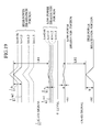
- Fig.6 shows the relation between the sum signal output (A+B+C+D) from the RF circuit 7 when reproducing the non-recording portion of the DVD 31 and the radial push-pull signal ⁇ (C+D)-k(A+B) ⁇ from the RPP generation circuit 8.
- the level of the RF signal obtained by adding each of the signals A-D is higher than the level of the radial push-pull signal, which is a differential signal obtained by subtracting ⁇ k(A+B) ⁇ from the (C+D) signal.
- the land pre-pit signal (LPP signal) which appears at a timing of 90° in the phase of the wobbling signal is overlaid on the wobbling signal (WBL signal) which vibrates up and down with respect to 0 level.
- the amplitude R1 of the sum signal (A+B+C+D), the amplitude W1 of the wobbling signal (WBL) and the amplitude L1 of the land pre-pit signal (LPP signal) are assumed to be values from 0 level to the highest points of respective signals shown in the same Figure.
- LPP signal As for the aforementioned land pre-pit signal (LPP signal), its signal on the normal side with respect to its track is shown here, while representation of the land pre-pit signal (LPP signal) on an opposite side to the normal side is omitted.
- Fig.7 is a diagram showing the radial push-pull signal ⁇ (C+D)-k(A+B) ⁇ when the non-recording portion described in Fig.6 is reproduced, with the (C+D) signal and the ⁇ -k(A+B) ⁇ signal having inverted polarity shown separately.
- the (C+D) signal appears on the side of the positive polarity with respect to 0 level, while the ⁇ -k(A+B) ⁇ signal appears on the side of the negative polarity with respect to 0 level.
- each of the (C+D) signal and ⁇ -k(A+B) ⁇ signal is composed of a wobbling signal and the land pre-pit signal (LPP signal) overlaid on the wobbling signal at a timing of 90° in the phase of the wobbling signal.
- the amplitude R2 up to the center level of the (C+D) signal on the side of the positive polarity and the amplitude kR2 up to the center level of the ⁇ -k(A+B) ⁇ signal on the side of the negative polarity are expressed with reference to the 0 level as shown in the same Figure.
- the amplitude W2 of the wobbling signal (WBL signal) corresponding to the (C+D) signal and the amplitude L2 of the land pre-pit signal (LPP signal) corresponding thereto are values extending from the center level of the (C+D) signal up to tops of the respective signals shown in the same Figure.
- the amplitude kW2 of the wobbling signal (WBL) corresponding to the ⁇ -k(A+B) ⁇ signal and the amplitude kL2 of the land pre-pit signal (LPP signal) corresponding thereto are values extending from the center level of the ⁇ -k(A+B) ⁇ signal up to tops of the respective signals shown in the same Figure.
- Fig.8 shows the state when information signal is recorded in the wobbling groove 32 in the DVD 31.
- a portion having a large irradiation amount of the light beam BM (portion corresponding to "information signal 1") is high-power irradiation portion and that a portion having a small irradiation amount of the light beam BM (portion corresponding to "information signal 0") is a low-power irradiation portion
- envelopes of the high-power irradiation portion and the low-power irradiation portion with respect to the (C+D) signal on the side of the positive polarity and the ⁇ -k(A+B) ⁇ signal on the side of the negative polarity are indicated separately.
- a case for recording will be described below. A description of the case for reproduction is omitted because the portion in which the recording pit is formed in the optical disc corresponds to the low-power irradiation portion while the non-recording portion in which the recording pit is not formed corresponds to the high-power irradiation portion at the time of reproduction and under this condition, the land pre-pit signal may be detected.
- the level of the ⁇ -k(A+B) ⁇ signal is adjusted by controlling the predetermined coefficient k in order to obtain a ⁇ -k(A+B) ⁇ signal having inverted polarity, so that the detection accuracy of the land pre-pit signal is improved in the subsequent stage.
- the radial push-pull signal it is permissible to employ the ⁇ (A+B)-k(C+D) ⁇ signal. In this case, the level of the ⁇ -k(C+D) ⁇ may be adjusted. A case where the level of the ⁇ -k(A+B) ⁇ signal is adjusted will be described below.
- light beam for recording is irradiated from the optical pickup 2 and this optical pickup 2 receives reflected light with the four-division photo detector PD described with reference to Fig.5A.
- Light reception signals in the light receiving regions A and B are supplied to the (A+B) adding circuit 4 through a pre-amplifier 3 and light reception signals in the light receiving regions C and D are supplied to the (C+D) adding circuit 5 through the pre-amplifier 3.
- the (A+B) adding circuit 4 sums up respective light reception signals from the light receiving regions A and B so as to generate the (A+B) signal and supplies this to the coefficient multiplying circuit 6 and the RF circuit 7.
- the (C+D) adding circuit 5 sums up respective light reception signals from the light receiving regions C and D so as to generate the (C+D) signal and supplies this to the RPP generation circuit 8 and the RF circuit 7.
- the RF circuit 7 sums up the (A+B) signal and the (C+D) signal so as to generate a sum signal, which is the (A+B+C+D) signal, and then supplies this to the LPPb generation circuit 14 and the WBLb generation circuit 15.
- An initial value of the coefficient of the coefficient multiplying circuit 6 is set up to "1" so as to output an inputted (A+B) signal just as it is without changing the level thereof.
- the predetermined coefficient k is changed according to feedback from the coefficient setting circuit 16 in the succeeding state as described later. Therefore, the RPP generation circuit 8 will be described with the predetermined coefficient k .
- the RPP generation circuit 8 computes a differential signal by subtracting the ⁇ k(A+B) signal ⁇ from the aforementioned (C+D) signal so as to generate the radial push-pull signal ⁇ (C+D)-k(A+B) ⁇ and then supplies this radial push-pull signal to the binarizing circuit 9, the LPP amplitude detecting circuit 12 and the WBL amplitude detecting circuit 13.
- the binarizing circuit 9 binarizes a land pre-pit signal (LPP signal) contained in the radial push-pull signal.
- the LPP amplitude detecting circuit 12 extracts a land pre-pit (LPP) component contained in the radial push-pull signal so as to detect the amplitude of the land pre-pit signal (LPP signal) and supplies this detection output to the LPPb generation circuit 14 and the coefficient setting circuit 16.
- LPP land pre-pit
- the WBL amplitude detecting circuit 13 extracts a wobble (WBL) component contained in the radial push-pull signal so as to detect the amplitude of the wobbling signal (WBL signal) and then supplies this detection output to the WBLb generation circuit 15 and the coefficient setting circuit 16.
- WBL wobble
- the LPPb generation circuit 14 computes a LPPb signal indicating the rate of the amplitude of the land pre-pit signal to a sum signal based on the sum signal from the RF circuit 7 and the amplitude of the LPP component contained in the radial push-pull signal detected by the LPP amplitude detecting circuit 12 and then supplies this to the coefficient setting circuit 16.
- the LPPb generation circuit 15 generates a LPPb signal normalized according to arithmetic operation based on the following equation (1) and then supplies this to the coefficient setting circuit 16.
- the WBLb generation circuit 15 computes a WBLb signal indicating the rate of the amplitude of the wobbling signal with respect to the sum signal from the RF circuit 7 based on the sum signal and a wobbling signal detected by the WBL amplitude detection circuit 13 and supplies its result to the coefficient setting circuit 16.
- the WBLb generation circuit 15 generates a WBLb signal normalized by computation based on a following equation (2) and then supplies its result to the coefficient setting circuit 16.
- the binarizing circuit 9 binarizes a land pre-pit signal (LPP signal) contained in the radial push-pull signal from the RPP generation circuit 8 and supplies the binarized land pre-pit signal (LPP signal) to the LPP decoding circuit 10.
- the LPP decoding circuit 10 decodes address information and the like contained in this binarized land pre-pit signal (LPP signal) according to this land pre-pit signal (LPP signal).
- an error rate upon detection of the land pre-pit signal (LPP signal) is supplied to the CPU 11.
- the CPU 11 supplies this error rate to the coefficient setting circuit 16 and thus corrects the predetermined coefficient k by an amount taking into account the error rate when the predetermined coefficient k is set up, described later, so as to reduce the error rate in this coefficient setting circuit 16.
- the lens shift amount detecting circuit 17 determines whether the center of the optical axis of the objective lens in the optical pickup 2 is shifted to the outer side in the radial direction of the DVD 31 or the inner side of the DVD 31 so as to detect a lens shift amount according to ⁇ depending on the outer side or the inner side.
- a lens shift amount signal indicating this lens shift amount is supplied to the coefficient setting circuit 16, so that the predetermined coefficient k is corrected by an amount taking into account the lens shift amount to the outer side or the inner side of the DVD 31 upon setting that predetermined coefficient k .
- the lens shift amount detecting circuit 17 comprises a slit plate provided on a bobbin for driving the objective lens, a light source for irradiating this slit plate, and a photo detector for receiving light equally through two divided light receiving regions (light receiving regions E, F), irradiated from the light source through a slit in the slit plate.
- a differential (E-F) of light reception amounts received by these light-receiving regions E, F of this photo detector is detected as a lens shift amount.
- DPP method Because in a system for detecting a tracking error according to the so-called differential push-pull method (DPP method), the DPP method itself cancels an influence of the lens shift, detection of objective lens offset based on the differential push-pull signal is disabled.
- DPP method itself cancels an influence of the lens shift, detection of objective lens offset based on the differential push-pull signal is disabled.
- a radial push-pull signal detecting system separately from the tracking error detection system based on the DPP method and detect an offset of the objective lens based on the radial push-pull signal detected with this radial push-pull signal detecting system while applying tracking servo according to the DPP method.
- the coefficient setting circuit 16 controls optimally the predetermined coefficient k of the coefficient setting circuit 16 as described below, according to the LPPb signal, the WBLb signal, the error rate and the lens shift amount signal, which are fed back when the predetermined coefficient k is adjusted to "1".
- a mini disc (MD), CD-R and the like have been well known.
- a recording and/or reproducing apparatus for the MD or CD-R adjusts a recording noise to be minimum at a cross point (zero cross point) between the wobbling signal shown in Fig.6 and the 0 level.
- the detection accuracy of the land pre-pit signal is improved by adjusting the recording noise to be minimum at a point slightly apart from the zero cross point.
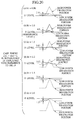
- Fig.9 is a diagram paying attention to only the land pre-pit signal in the radial push-pull signal by removing the wobbling signal component on an assumption that the wobbling signal component in the radial push-pull signal is zero.
- the positive polarity side relative to 0 level indicates the land pre-pit signal in the high-power irradiation portion and the land pre-pit signal in the low-power irradiation portion of the (C+D) signal.
- the negative polarity side relative to 0 level indicates the land pre-pit signal in the high-power irradiation portion and the land pre-pit signal in the low-power irradiation portion of the ⁇ -k(A+B) ⁇ signal.
- the land pre-pit signal in the low-power irradiation portion and the land pre-pit signal in the high-power irradiation portion are indicated about a case where the predetermined coefficient k for multiplication processing is changed from, for example, near 0.9 to near 1.6 for simulation.
- the under level of the land pre-pit signal in the low-power irradiation portion is "m1”
- the under level of the land pre-pit signal in the high-power irradiation portion is "m2”
- a peak level relative to the under level of the land pre-pit signal in the low-power irradiation portion is "a”
- the peak level relative to the under level of the land pre-pit signal in the high-power irradiation portion is "b”
- the amplitude LB1 which is an amplitude from a top of a land pre-pit signal waveform in the high-power irradiation portion to a top of the land pre-pit signal waveform in the low-power irradiation portion can be computed in the following equation (3).
- the amplitude LB2 which is an amplitude from the top of the land pre-pit signal waveform in the low-power irradiation portion to the top of the land pre-pit signal waveform in the high-power irradiation portion can be computed in the following equation (4).
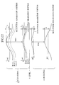
- Case (b) in Fig.10 shows a case where the predetermined coefficient k is set up to "1.0", in which the radial push-pull signal ⁇ (C+D)-(A+B) ⁇ is obtained like conventionally.
- the under level of the land pre-pit signal in the high-power irradiation portion and the under level of the landpre-pit signal in the low-power irradiation portion become the same reference level (hereinafter referred to as 0 level). Consequently, the wobbling signal, whose representation is omitted here, can be detected favorably, however the land pre-pit signal cannot be detected so favorably.
- the aforementioned slice window width for detecting the landpre-pit signal in the high-power irradiation portion and the land pre-pit signal in the low-power irradiation portion becomes 4.0, which is a difference of level between the peak level of the land pre-pit signal in the low-power irradiation portion and 0 level. Because this slice windowwidth, which is 4.0, is quite small, both the land pre-pit signals cannot be detected securely.
- the predetermined coefficient k is set to "0.96", which is slightly smaller than "1.0" as shown in case (a) in Fig.10 as compared to the above-explained case (b), the under level of the land pre-pit signal in the high-power irradiation portion and the under level of the land pre-pit signal in the low-power irradiation portion are raised above 0 level.
- the aforementioned slice window width for detecting both the land pre-pit signals becomes 0.92, which is a difference of level between the peak level of the land pre-pit signal in the low-power irradiation portion and the under level of the land pre-pit signal in the high-power irradiation portion.
- This slice window width which is 0.92, is extremely smaller than that of case (b) in Fig.10, so that detection of the land pre-pit signal is disabled and further, the wobbling signal, whose representation is omitted, is worse than the case (b) in Fig.10.
- the wobbling signal whose representation is omitted, is inferior to the case (b) in Fig.10, it is a more important matter that the land pre-pit signal can be detected securely than that the detection of the wobbling signal is deteriorated. In cases (d) to (f) in Fig.10, detection of the wobbling signal is deteriorated gradually.
- the predetermined coefficient k is set to "1.2" which is larger than that of case (c) in Fig.10, the same tendency occurs, but the slice window width for detecting both the land pre-pit signals becomes 4.4, which is a difference of level between the peak level of the land pre-pit signal in the low-power irradiation portion and the under level of the land pre-pit signal in the low-power irradiation portion.
- This slice window width of 4.4 is a favorable value capable of detecting both the land pre-pit signals reliably and securely.
- the predetermined coefficient k is set to "1.5", which is larger than that of case (d) in Fig.10, the under level of the land pre-pit signal in the high-power irradiation portion and the under level of the land pre-pit signal in the low-power irradiation portion drop below 0 level.
- the peak level of the land pre-pit signal in the high-power irradiation portion and the peak level of the land pre-pit signal in the low-power irradiation portion coincide with each other at 0 level.
- this slice window width which is 5.0, becomes the maximum value capable of detecting both the land pre-pit signals securely.
- the predetermined coefficient k is set to "1.6" which is larger than the value of case (d) in Fig. 10, both the peak level of the land pre-pit signal in the high-power irradiation portion and the peak level of the land pre-pit signal in the low-power irradiation portion drop below 0 level and at the same time, the peak level of the land pre-pit signal in the high-power irradiation portion becomes lower than the peak level of the land pre-pit signal in the low-power irradiation portion.
- the slice window width for detecting both the land pre-pit signals becomes 2.0, which is a difference of level between the peak level of the land pre-pit signal in the high-power irradiation portion and the under level of the land pre-pit signal in the low-power irradiation portion.
- This slice window width of 2.0 is extremely low although the predetermined coefficient k is increased slightly by 0.1 from the case (e) in Fig.10, so that detection of both the land pre-pit signals is worsened extremely.
- the slice window width for detecting both the land pre-pit signal in the high-power irradiation portion and the land pre-pit signal in the low-power irradiation portion with respect to the predetermined coefficient k is obtained according to substantially the same concept as described in Fig.10.
- the reason why the absolute value of the obtained slice window width is different from an absolute value obtained in Fig.10 is that other factors than the predetermined coefficient k are different.
- case (a) in Fig.11 shows a case where the predetermined coefficient k is set to "0.9".
- the under level of the land pre-pit signal in the high-power irradiation portion and the under level of the land pre-pit signal in the low-power irradiation portion rise over 0 level and at the same time, the aforementioned slice window width for detecting the land pre-pit signal in the high-power irradiation portion and the land pre-pit signal in the low-power irradiation portion becomes 3.5, which is a difference of level between the peak level of the land pre-pit signal in the low-power irradiation portion and the under level of the land pre-pit signal in the high-power irradiation portion.
- This value of 3.5 is so small that detection of the land pre-pit signal is disabled.
- case (b) in Fig.11 shows a case where the predetermined coefficient k is set to "1.0" and in this case, the radial push-pull signal ⁇ (C+D)-(A+B) ⁇ is obtained like conventionally.
- both the under level of the land pre-pit signal in the high-power irradiation portion and the under level of the land pre-pit signal in the low-power irradiation portion become 0 level (reference level), so that although the wobbling signal, whose representation is omitted, can be detected favorably, detection of the land pre-pit signal is not carried out so favorably. That is, the slice window width for detecting both the land pre-pit signals becomes 8.0, which is a difference of level between the peak level of the land pre-pit signal in the low-power irradiation portion and 0 level. This slice window width of 8.0 is smaller than required, so that both the land pre-pit signals cannot be detected securely.
- Case (c) in Fig.11 shows a case where the predetermined coefficient k is set to "1.1".
- both the under level of the land pre-pit signal in the high power irradiation portion and the under level of the land pre-pit signal in the low power irradiation portion drop below 0 level.
- the aforementioned slice window width for detecting both the land pre-pit signals becomes 8.4, which is a difference of level between a peak level of the land pre-pit signal in the low-power irradiation portion and the under level of the land pre-pit signal in the low-power irradiation portion.
- This slice window width of 8.4 is a favorable value capable of detecting both the land pre-pit signals reliably and securely.
- Case (d) in Fig.11 shows a case where the predetermined coefficient k is set to "1.2".
- both the under level of he land pre-pit signal in the high-power irradiation portion and the under level of the land pre-pit signal in the low-power irradiation portion drop below 0 level, so that the peak level of the land pre-pit signal in the high-power irradiation portion coincides with the peak level of the land pre-pit signal in the low-power irradiation portion above 0 level.
- the aforementioned slice window width for detecting both the land pre-pit signals becomes 8.8, which is a difference of level between the peak level of the land pre-pit signal in the high-power irradiation portion and low-power irradiation portion and the under level of the land pre-pit signal in the low-power irradiation portion.
- Case (e) in Fig.11 shows a case where the predetermined coefficient k is set to "1.3".
- both the peak level of the land pre-pit signal in the high-power irradiation portion and the peak level of the land pre-pit signal in the low-power irradiation portion drop below 0 level and at the same time, the peak level of the land pre-pit signal in the high-power irradiation portion is lower than the peak level of the land pre-pit signal in the low-power irradiation portion.
- the slice window width for detecting both the land pre-pit signals becomes 7.0, which is a difference of level between the peak level of the land pre-pit signal in the high-power irradiation portion and the under level of the land pre-pit signal in the low-power irradiation portion.
- This slice window width of 7.0 is smaller than those of cases (c) and (d) in Fig.11, so that detection of both the land pre-pit signals is worsened.
- the case where the predetermined coefficient k is "1.2" indicates a theoretical upper limit. If this theoretical upper limit is set up, the predetermined coefficient k has no allowance in a direction in which it is increased over 1.2.
- the case where the predetermined coefficient k is near "1.1" indicates an actual value under a/m1 ⁇ b/m2 ⁇ L.
- a coefficient ⁇ in the equations (7), (8) is affected by performance of the optical pickup 2, recording power in the optical pickup 2 and reproduction power in reproduction mode and may be smaller than 1.0.
- This coefficient ⁇ may be stored in a memory preliminarily.
- Fig.12 is a diagram in which attention is paid to only the wobbling signal in the radial push-pull signal by removing the land pre-pit signal component by zeroing the land pre-pit signal component in the radial push-pull signal.
- the side of positive polarity relative to 0 level indicates the wobbling signal in the high-power irradiation portion of the (C+D) signal and the wobbling signal in the low-power irradiation portion thereof.
- the side of negative polarity relative to 0 level indicates the wobbling signal in the high-power irradiation portion of the ⁇ -k(A+B) ⁇ signal and the wobbling signal in the low-power irradiation portion thereof.
- a simulation for the ⁇ -k(A+B) ⁇ signal is carried out by changing the predetermined coefficient k to be multiplied in the same manner as described in Fig.9. For convenience of representation, only cases where the predetermined coefficient k is 1.0, 1.1, 1.2 are indicated here.
- Case (a) in Fig.13 is a case where the predetermined coefficient k is set up to "1.0", in which the radial push-pull signal ⁇ (C+D)-(A+B) ⁇ is obtained like conventionally.
- the wobbling signal in the high-power irradiation portion and the wobbling signal in the low-power irradiation portion are both in the same cycle and further, the amplitude of the wobbling signal in the high-power irradiation portion is larger than the amplitude of the wobbling signal in the low-power irradiation portion.
- This state corresponds to case (b) in Fig.10 described previously, in which although the wobbling signal can be detected favorably, detection of the land pre-pit signal is not carried out so favorably.
- Case (b) in Fig.13 shows a case where the predetermined coefficient k is set to "1.1".
- the wobbling signal in the high-power irradiation portion and the wobbling signal in the low-power irradiation portion have respective cycles different from each other.
- the top of the wobbling signal waveform in the low-power irradiation portion coincides with the top of the wobbling signal waveform in the high-power irradiation portion above the center level and in this state
- Case (c) in Fig.13 shows a case where the predetermined coefficient k is set to "1.2".
- the top of the wobbling signal in the high-power irradiation portion is located below the top of the waveform of the wobbling signal in the low-power irradiation portion such that it does not intersect therewith.
- This state corresponds to case (d) in Fig.10 described previously, in which although the detection of the wobbling signal is worsened further, detection of the land pre-pit signal is improved (this has been already described).
- a coefficient ⁇ in the equations (13), (14) is affected by performance of the optical pickup 2, recording power in the optical pickup 2 and reproduction power in reproduction mode and may be smaller than 1.0.
- This coefficient (3 may be stored in a memory preliminarily.
- the equations (5), (6), (7), (8) described about the land pre-pit signal are established individually and further, the equations (11), (12), (13), (14) described about the wobbling signal are established individually.
- the equations about the land pre-pit signal and the equations about the wobbling signal only should be combined for each purpose.
- the predetermined coefficient k is conventionally set to "1.0"
- the predetermined coefficient k is set larger than 1.0 and in a range capable of detecting the land pre-pit signal through feedback process, based on i ) the amplitude of the land pre-pit signal or the amplitude of the land pre-pit signal and the amplitude of the wobbling signal; or the predetermined coefficient k is set larger than 1.0 and in a range capable of detecting the land pre-pit signal based on the ii) the amplitude of the normalized land pre-pit signal or the amplitude of the normalized land pre-pit signal and the amplitude of the normalized wobbling signal.
- the land pre-pit signal can be detected at a high precision securely, so that upon recording or reproducing into/from a disc-like recording medium, the land pre-pit signal corresponding to a land pre-pit formed in the land 33 can be detected at a high precision.
- the coefficient setting circuit 16 sets the predetermined coefficient k to be set in the coefficient multiplying circuit 6 in a range from the aforementioned theoretical upper limit value and the theoretical lower limit value, based on the LPP signal, WBL signal, LPPb signal, WBLb signal, an error rate upon detecting of the land pre-pit signal and a shift amount of an objective lens of the optical pickup 2. More specifically, the predetermined coefficient k is set larger than 1.0 and in a range capable of detecting the land pre-pit signal.
- the land pre-pit signal can be detected securely at a high precision irrespective of the high-power irradiation portion and the low-power irradiation portion on the DVD 31. Further, the land pre-pit signal can be detected securely at a high precision irrespective of a recording pit formation position and space portion (non-recording portion) on the DVD 31.
- Fig.14 is a block diagram of a disc recording and/or reproducing apparatus of a second embodiment.
- the disc recording and/or reproducing apparatus of the second embodiment comprises an optical pickup 2 for carrying out recording and/or reproduction of data by irradiating the DVD 31 with light beam from a semiconductor laser (not shown) through an objective lens (not shown) and a preamplifier 3 for amplifying an output of the optical pickup 2 at a predetermined gain and outputting its result.
- Fig.15A is a schematic diagram showing a condition in which the photo detector PD in the optical pickup is located in the center of a wobbling groove 32 and a land pre-pit 34 on a land 33 on the right of the same Figure is being detected with this photo detector PD.
- the aforementioned photo detector PD is formed in a substantially rectangular form and its entire light-receiving region is divided equally to four sections with a straight line along the diameter direction of the DVD 31 and a line along the track direction.
- the light spot SP focused on this photo detector PD is comprised of two pairs, which are a combination of a light receiving region A and a light receiving region B located on the outer side with respect to the DVD 31 and a combination of a light receiving region C and a light receiving region D located on the inner side, so that it is divided to two sections with respect to a straight line along the direction of the recording track of the DVD 31.
- (A+B) signal obtained by summing up light reception signals from the two light receiving regions A and B on the outer side of the DVD 31 and (C+D) signal obtained by summing up light reception signals from the two light receiving regions C and D on the inner side of the DVD 31 are outputted.
- brightnesses on the outer side and inner side of the DVD 31 are unbalanced due to an influence by refraction of the light beam BM to the land pre-pit 34 on the photo detector PD.
- the (A+B) signal and the (C+D) signal are outputted as one is a turned-over type of the other on the side above 0 level.
- the output amplitude of the (A+B) signal and the output amplitude of the (C+D) signal be substantially of the same level. If both the signals are not substantially the same level due to adjustment condition of the optical pickup or the like, the (A+B) adding circuit and the (C+D) adding circuit only have to be adjusted with an appropriate adjusting circuit, so that output amplitudes of both are substantially of the same level, before a differential signal is produced with a RPP generation circuit 8, which will be described later.
- a multiplication processing of multiplying a predetermined coefficient p with minus sign has to be carried out only on the signal (A+B) including the land pre-pit signal (LPP signal) directed to 0 level (directed downward) with respect to the wobbling signal (WBL signal).
- the (C+D) includes the land pre-pit signal (LPP signal) directed downward, different from shown here, the (C+D) may be subjected to multiplication processing of being multiplied with the coefficient p while the other is multiplied with a coefficient q .
- this determination is not carried out in the apparatus and further, which should be subjected to the multiplication processing can be set up preliminarily.
- the disc recording and/or reproducing apparatus comprises the (A+B) adding circuit 4 for detecting the (A+B) signal obtained by summing the light reception signals from the two light receiving regions A and B on the outer side of the DVD 31 and a (C+D) adding circuit 5 for detecting the (C+D) signal obtained by summing the reception signals from the two light receiving regions C and D on the inner side of the DVD 31.
- the disc recording and/or reproducing apparatus contains a coefficient p multiplying circuit 6a, which inverts the polarity of the (A+B) signal from the (A+B) adding circuit 4 and multiplies with a predetermined coefficient p so as to output ⁇ -p(A+B) ⁇ .
- the disc recording and/or reproducing apparatus comprises a coefficient q multiplying circuit 20, which multiplies the (C+D) signal from the (C+D) adding circuit 5 with a predetermined coefficient q so as to output ⁇ q(C+D) ⁇ .
- the detection accuracy of the land pre-pit (LPP) on the optical disc is improved.
- the disc recording and/or reproducing apparatus comprises a RPP generation circuit 8a for generating the radial push-pull signal ⁇ q(C+D)-p(A+B) ⁇ , a binarizing circuit 9 for binarizing the land pre-pit signal (LPP signal) contained in the radial push-pull signal from the RPP generation circuit 8a, a LPP decoding circuit 10 for decoding address information and the like of the land pre-pit signal (LPP signal) binarized by the binarizing circuit 9 and a CPU 11 which computes an error rate of the land pre-pit signal decoded by the LPP decoding circuit 10 and outputting this error rate.
- a RPP generation circuit 8a for generating the radial push-pull signal ⁇ q(C+D)-p(A+B) ⁇
- a binarizing circuit 9 for binarizing the land pre-pit signal (LPP signal) contained in the radial push-pull signal from the RPP generation circuit 8a
- LPP decoding circuit 10 for de
- the disc recording and/or reproducing apparatus comprises an RF circuit 7 for generating a sum signal ⁇ RF signal: (A+B+C+D)) ⁇ by summing up the (A+B) signal from the (A+B) adding circuit 4 and the (C+D) signal from the (C+D) adding circuit 5, an LPP amplitude detecting circuit (land pre-pit signal amplitude detecting circuit) 12, which extracts a land pre-pit signal (LPP signal) from the radial push-pull signal sent from the RPP generation circuit 8a, detects the amplitude of this land pre-pit signal and outputs its result to an LPPb generation circuit 14 and the coefficient setting circuit 12, and a WBL amplitude detecting circuit (wobbling signal amplitude detecting circuit) 13, which extracts a wobbling signal (WBL signal) of the recording track from the radial push-pull signals sent from the RPP generation circuit 8a, detects the amplitude of this wobbling signal and outputs its result to a W
- this disc recording and/or reproducing apparatus comprises the LPPb generation circuit (normalization land pre-pit signal amplitude detecting circuit) 14, which outputs the level of a land pre-pit signal (LPP signal) extracted by the LPP amplitude detecting circuit 12 as a land pre-pit signal (hereinafter referred to as LPPb signal) normalized with respect to the level of a sum signal (A+B+C+D) generated by the RF circuit 7, the WBLb generation circuit (normalized wobbling signal amplitude detecting circuit) 15, which outputs the level of a wobbling signal extracted by the WBL amplitude detecting circuit 13 as a wobbling signal (hereinafter referred to as WBLb signal) normalized with respect to the level of the sum signal (A+B+C+D) generated by the RF circuit 7 and a lens shift amount detecting circuit 17, which detects a lens shift amount in the radial direction from the center of optical axis of an objective lens in the optical pickup 2 and outputs this lens shift amount.
- the disc recording and/or reproducing apparatus comprises the coefficient setting circuit 16 for setting the predetermined coefficient p of the coefficient p multiplying circuit 6a and the predetermined coefficient q of the coefficient q multiplying circuit 20 depending on the error rate from the CPU 11 upon detecting the land pre-pit signal, the amplitude of a land pre-pit signal from the LPP amplitude detecting circuit 12, the amplitude of a wobbling signal from the WBL amplitude detecting circuit 13, the normalized LPPb signal from the WBLb generation circuit 15 and the lens shift amount detected by the lens shift amount detecting circuit 17.
- LPP land pre-pit
- the wobbling signal and LPP signal are expressed with a straight line approximately and different from Figs. 22, 23 because they are expressed only in a simplified way.
- the present invention includes reproducing a non-recording portion and thus measuring a related basic parameter about that disc. Because in an actual recording and/or reproducing apparatus, the non-recording region on the disc can be recognized, it is possible to seek that region so as to obtain the aforementioned parameter.
- a read-in region on the most inside periphery of the disc and a read-out region on the most outer periphery of the disc are portions to be recorded after all user data are recorded into this disc and after this region is recorded, anymore recording is not carried out in this disc. Measurement of the related basic parameter about the disc of the present invention can be carried out from the lead-in region or the lead-out region.
- Fig.16 shows the relation between the sum signal output (A+B+C+D) from the RF circuit 7 when reproducing the non-recording portion of the DVD 31 and the radial push-pull signal ⁇ q(C+D)-p(A+B) ⁇ from the RPP generation circuit 8a.
- the level of the RF signal obtained by adding each of the signals A-D is higher than the level of the radial push-pull signal, which is a differential signal obtained by subtracting p(A+B) from the q(C+D) signal.
- the land pre-pit signal (LPP signal) which appears at a timing of 90° in the phase of the wobbling signal is overlaid on the wobbling signal (WBL signal) which vibrates up and down with respect to 0 level.
- the amplitude R1 of the sum signal (A+B+C+D), the amplitude W1 of the wobbling signal (WBL) and the amplitude L1 of the land pre-pit signal (LPP signal) are assumed to be values from 0 level to the highest points of respective signals shown in the same Figure.
- LPP signal As for the aforementioned land pre-pit signal (LPP signal), its signal on the normal side with respect to its track is shown here, while representation of the land pre-pit signal (LPP signal) on an opposite side to the normal side is omitted.
- Fig.17 is a diagram showing the radial push-pull signal ⁇ q(C+D)-p(A+B) ⁇ when the non-recording portion described in Fig.16 is reproduced, with the q(C+D) signal and the ⁇ -p(A+B) ⁇ signal having inverted polarity shown separately.
- the p(C+D) signal appears on the side of the positive polarity with respect to 0 level, while the ⁇ -q(A+B) ⁇ signal appears on the side of the negative polarity with respect to 0 level.
- each of the q(C+D) signal and ⁇ -p(A+B) ⁇ signal is composed of a wobbling signal and the land pre-pit signal (LPP signal) overlaid on the wobbling signal at a timing of 90° in the phase of the wobbling signal.
- the amplitude qR2 up to the center level of the q(C+D) signal on the side of the positive polarity and the amplitude pR2 up to the center level of the ⁇ -p(A+B) ⁇ signal on the side of the negative polarity are expressed with reference to the 0 level as shown in the same Figure.
- the amplitude qW2 of the wobbling signal (WBL signal) corresponding to the q(C+D) signal and the amplitude qL2 of the land pre-pit signal (LPP signal) correspond thereto are values extending from the center level of the q(C+D) signal up to tops of the respective signals shown in the same Figure.
- the amplitude pW2 of the wobbling signal (WBL) corresponding to the ⁇ -p(A+B) ⁇ signal and the amplitude pL2 of the land pre-pit signal (LPP signal) corresponding thereto are values extending from the center level of the ⁇ -p(A+B) ⁇ signal up to tops of the respective signals shown in the same Figure.
- Fig.18 shows the state when information signal is recorded in the wobbling groove 32 in the DVD 31.
- a portion having a large irradiation amount of the light beam BM (portion corresponding to "information signal 1") is high-power irradiation portion and that a portion having a small irradiation amount of the light beam BM (portion corresponding to "information signal 0") is a low-power irradiation portion
- envelopes of the high-power irradiation portion and the low-power irradiation portion with respect to the q(C+D) signal on the side of the positive polarity and the ⁇ -p(A+B) ⁇ signal on the side of the negative polarity are indicated separately.
- a case for recording will be described below. A description of the case for reproduction is omitted because the portion in which the recording pit is formed in the optical disc corresponds to the low-power irradiation portion while the non-recording portion in which the recording pit is not formed corresponds to the high-power irradiation portion at the time of reproduction and under this condition, the land pre-pit signal may be detected.
- the detection accuracy of the land pre-pit signal in the radial push-pull signal ⁇ q(C+D)-p(A+B) ⁇ is improved in the subsequent stage.
- light beam for recording is irradiated from the optical pickup 2 and this optical pickup 2 receives reflected light with the four-division photo detector PD described with reference to Fig.15A.
- Light reception signals in the light receiving regions A and B are supplied to the (A+B) adding circuit 4 through a pre-amplifier 3 and light reception signals in the light receiving regions C and D are supplied to the (C+D) adding circuit 5 through the pre-amplifier 3.
- the (A+B) adding circuit 4 sums up respective light reception signals from the light receiving regions A and B so as to generate the (A+B) signal and supplies this to the coefficient p multiplying circuit 6 and the RF circuit 7.
- the (C+D) adding circuit 5 sums up respective light reception signals from the light receiving regions C and D so as to generate the (C+D) signal and supplies this to the RPP generation circuit 8a and the RF circuit 7.
- the RF circuit 7 sums up the (A+B) signal and the (C+D) signal so as to generate a sum signal which is the (A+B+C+D) signal, and then supplies this to the LPPb generation circuit 14 and the WBLb generation circuit 15.
- Initial values of the coefficients of the coefficient p multiplying circuit 6a and the coefficient q multiplying circuit 20 are set up to "1" so as to output inputted (A+B) signal and (C+D) signal just as they are, without changing the levels thereof. Although they are supplied to the RPP generation circuit 8a as they are in the initial state, the predetermined coefficients p , q are changed according to feedback from the coefficient setting circuit 16 in the succeeding stage as described later. Therefore, the RPP generation circuit 8a will be described with the predetermined coefficients p , q .
- the RPP generation circuit 8a computes a differential signal by subtracting the ⁇ p(A+B) signal ⁇ from the aforementioned q(C+D) signal so as to generate the radial push-pull signal ⁇ q(C+D)-p(A+B) ⁇ and then supplies this radial push-pull signal to the binarizing circuit 9, the LPP amplitude detecting circuit 12 and the WBL amplitude detecting circuit 13.
- the binarizing circuit 9 binarizes a land pre-pit signal (LPP signal) contained in the radial push-pull signal.
- the LPP amplitude detecting circuit 12 extracts a land pre-pit (LPP) component contained in the radial push-pull signal so as to detect the amplitude of the land pre-pit signal (LPP signal) and supplies this detection output to the LPPb generation circuit 14 and the coefficient setting circuit 16.
- LPP land pre-pit
- the WBL amplitude detecting circuit 13 extracts a wobble (WBL) component contained in the radial push-pull signal so as to detect the amplitude of the wobbling signal (WBL signal) and then supplies this detection output to the WBLb generation circuit 15 and the coefficient setting circuit 16.
- WBL wobble
- the LPPb generation circuit 14 computes a LPPb signal indicating the rate of the amplitude of the land pre-pit signal to a sum signal based on the sum signal from the RF circuit 7 and the amplitude of the LPP component contained in the radial push-pull signal detected by the LPP amplitude detecting circuit 12 and then supplies this to the coefficient setting circuit 16.
- the LPPb generation circuit 15 generates a LPPb signal normalized according to arithmetic operation based on the following equation (19) and then supplies this to the coefficient setting circuit 16.
- the WBLb generation circuit 15 computes a WBLb signal indicating the rate of the amplitude of the wobbling signal with respect to the sum signal from the RF circuit 7 based on the sum signal and a wobbling signal detected by the WBL amplitude detection circuit 13 and supplies its result to the coefficient setting circuit 16.
- the WBLb generation circuit 15 generates a WBLb signal normalized by computation based on the equation (20) and then supplies its result to the coefficient setting circuit 16.
- the binarizing circuit 9 binarizes a land pre-pit signal (LPP signal) contained in the radial push-pull signal from the RPP generation circuit 8 and supplies the binarized land pre-pit signal (LPP signal) to the LPP decoding circuit 10.
- the LPP decoding circuit 10 decodes address information and the like contained in this binarized land pre-pit signal (LPP signal) according to this land pre-pit signal (LPP signal).
- an error rate upon detection of the land pre-pit signal (LPP signal) is supplied to the CPU 11.
- the CPU 11 supplies this error rate to the coefficient setting circuit 16 and thus corrects the predetermined coefficients p , q by an amount taking into account the error rate when the predetermined coefficients p , q are set up, described later, so as to reduce the error rate in this coefficient setting circuit 16.
- the lens shift amount detecting circuit 17 determines whether the center of the optical axis of the objective lens in the optical pickup 2 is shifted to the outer side in the radial direction of the DVD 31 or the inner side of the DVD 31 soas to detect a lens shift amount according to ⁇ depending on the outer side or the inner side.
- a lens shift amount signal indicating this lens shift amount is supplied to the coefficient setting circuit 16, so that the predetermined coefficients p , q are corrected by an amount taking into account the lens shift amount to the outer side or the inner side of the DVD 31 upon setting that predetermined coefficients p , q .
- the lens shift amount detecting circuit 17 comprises a slit plate provided on a bobbin for driving the objective lens, alight source for irradiating this slit plate, and a photo detector for receiving light equally through two divided light receiving regions (light receiving regions E, F), irradiated from the light source through a slit in the slit plate.
- a differential (E-F) of light reception amounts received by these light receiving regions E, F of this photo detector is detected as a lens shift amount.
- DPP method Because in a system for detecting a tracking error according to the so-called differential push-pull method (DPP method), the DPP method itself cancels an influence of the lens shift, detection of objective lens offset based on the differential push-pull signal is disabled.
- DPP method itself cancels an influence of the lens shift, detection of objective lens offset based on the differential push-pull signal is disabled.
- a radial push-pull signal detecting system separately from the tracking error detection system based on the DPP method and detect an offset of the objective lens based on the radial push-pull signal detected with this radial push-pull signal detecting system while applying tracking servo according to the DPP method.
- the coefficient setting circuit 16 controls optimally the predetermined coefficient p of the coefficient p multiplying circuit 6a and the predetermined coefficient q of the coefficient q multiplying circuit 20 as described below, according to the LPPb signal, the WBLb signal, the error rate and the lens shift amount signal, which are fed back when the predetermined coefficients p , q are adjusted to "1".
- a mini disc (MD), CD-R and the like have been well known.
- a recording and/or reproducing apparatus for this MD or CD-R adjusts a recording noise to be minimum at a cross point (zero cross point) between the wobbling signal shown in Fig.16 and the 0 level.
- the detection accuracy of the land pre-pit signal is improved by adjusting the recording noise to be minimum at a point slightly apart from the zero cross point.
- Fig.19 is a diagram paying attention to only the land pre-pit signal in the radial push-pull signal by removing the wobbling signal component on an assumption that the wobbling signal component in the radial push-pull signal is zero.
- the positive polarity side relative to 0 level indicates the land pre-pit signal in the high-power irradiation portion and the land pre-pit signal in the low-power irradiation portion of the (1/k1)(C+D) signal.
- the negative polarity side relative to 0 level indicates the land pre-pit signal in the high-power irradiation portion and the land pre-pit signal in the low-power irradiation portion of the (A+B) signal.
- the land pre-pit signal in the low-power irradiation portion and the land pre-pit signal in the high-power irradiation portion are indicated about a case where the predetermined coefficient 1/k1 for multiplication processing is changed from, for example, near 0.6 to near 1.1 (changing k1 for example, from 0.96 to 1.5) for simulation.
- the amplitude LB1 which is an amplitude from a top of a land pre-pit signal waveform in the high-power irradiation portion to a top of the land pre-pit signal waveform in the low-power irradiation portion can be computed in a following equation (21).
- the under level of the land pre-pit signal in the low-power irradiation portion is "-m1”
- the under level of the land pre-pit signal in the high-power irradiation portion is "-m2”
- a peak level relative to the under level of the land pre-pit signal in the low-power irradiation portion is "a”
- the peak level relative to the under level of the land pre-pit signal in the high-power irradiation portion is "b”
- the amplitude LB2 which is an amplitude from the top of the land pre-pit signal waveform in the low-power irradiation portion to the top of the land pre-pit signal waveform in the high-power irradiation portion can be computed in a following equation (22).
- the under level of the land pre-pit signal in the high-power irradiation portion and the under level of the land pre-pit signal in the low-power irradiation portion become the same reference level (hereinafter referred to as 0 level). Consequently, the wobbling signal, whose representation is omitted here, can be detected favorably, however the land pre-pit signal cannot be detected so favorably.
- the aforementioned slice window width for detecting the landpre-pit signal in the high-power irradiation portion and the land pre-pit signal in the low-power irradiation portion becomes 4.00, which is a difference of level between the peak level of the land pre-pit signal in the low-power irradiation portion and 0 level. Because this slice window width, which is 4.00, is quite large, this slice window width is decreased quickly if the value k1 is decreased, which is a problem to be solved.
- the aforementioned slice window width for detecting both the land pre-pit signals becomes 2.41, which is a difference of level between the peak level of the land pre-pit signal in the low-power irradiation portion and the under level of the land pre-pit signal in the high-power irradiation portion.
- This slice window width which is 2.41, is extremely smaller than that of case (b) in Fig.20, so that detection of the land pre-pit signal is disabled and further, the wobbling signal, whose representation is omitted, is slightly worse than the case (b) in Fig.20.
- the wobbling signal whose representation is omitted, is slightly inferior to the case (b) in Fig.20, it is a more important matter that the land pre-pit signal can be detected securely than that the detection of the wobbling signal is deteriorated. In cases (d) to (f) in Fig.20, detection of the wobbling signal is deteriorated gradually.
- the slice window width for detecting both the land pre-pit signals becomes 3.67, which is a difference of level between the peak level of the land pre-pit signal in the low-power irradiation portion and the under level of the land pre-pit signal in the low-power irradiation portion.
- This slice window width of 3.67 is an excellent value capable of detecting both the land pre-pit signals reliably and securely.
- the peak level of the land pre-pit signal in the high-power irradiation portion and the peak level of the land pre-pit signal in the low-power irradiation portion coincide with each other at 0 level.
- the slice windowwidth for detecting both the land pre-pit signals becomes 1.25, which is a difference of level between the peak level of the land pre-pit signal in the high-power irradiation portion and the peak level of the land pre-pit signal in the low-power irradiation portion.
- This slice window width of 1.25 is a extremely decreased value although the predetermined coefficient k1 is increased slightly by 0.1 from the case (e) in Fig.20, so that detection of both the land pre-pit signals is worsened extremely.
- the slice window width for detecting both the land pre-pit signal in the high-power irradiation portion and the land pre-pit signal in the low-power irradiation portion with respect to the predetermined coefficient k1 is obtained according to substantially the same concept as described in Fig.20.
- the reason why the absolute value of the obtained slice window width is different from an absolute value obtained in Fig.20 is that other factors than the predetermined coefficient k1 are different.
- both the under level of the land pre-pit signal in the high-power irradiation portion and the under level of the land pre-pit signal in the low-power irradiation portion rises over 0 level and at the same time, the aforementioned slice window width for detecting the land pre-pit signal in the high-power irradiation portion and the land pre-pit signal in the low-power irradiation portion becomes 4.00, which is a difference of level between the peak level of the land pre-pit signal in the low-power irradiation portion and the under level of the land pre-pit signal in the high-power irradiation portion. This value of 4.00 is so small that detection of the land pre-pit signal is disabled.
- case (b) in Fig.21 shows a case where the predetermined coefficient k1 is set to "1.0" and in this case, the radial push-pull signal ⁇ (C+D)-(A+B) ⁇ is obtained like conventionally.
- both the under level of the land pre-pit signal in the high-power irradiation portion and the under level of the land pre-pit signal in the low-power irradiation portion become 0 level (reference level), so that although the wobbling signal, whose representation is omitted, can be detected favorably, detection of the land pre-pit signal is not carried out so favorably. That is, the slice window width for detecting both the land pre-pit signals becomes 8.00, which is a difference of level between the peak level of the land pre-pit signal in the low-power irradiation portion and 0 level. Although this slice window width of 8.00 is larger than required, if the value of k1 is decreased, the slice window width is decreased quickly.
- both the under level of the land pre-pit signal in the high power irradiation portion and the under level of the land pre-pit signal in the low power irradiation portion drop below 0 level.
- the aforementioned slice window width for detecting both the land pre-pit signals becomes 7.64, which is a difference of level between a peak level of the land pre-pit signal in the low-power irradiation portion and the under level of the land pre-pit signal in the low-power irradiation portion.
- This slice window width of 7.64 is a favorable value capable of detecting both the land pre-pit signals reliably and securely.
- both the under level of he land pre-pit signal in the high-power irradiation portion and the under level of the land pre-pit signal in the low-power irradiation portion drop below 0 level, so that the peak level of the land pre-pit signal in the high-power irradiation portion coincides with the peak level of the land pre-pit signal in the low-power irradiation portion above 0 level.
- Case (e) in Fig. 21 shows a case where the predetermined coefficient k1 is set to "1.3".
- both the peak level of the land pre-pit signal in the high-power irradiation portion and the peak level of the land pre-pit signal in the low-power irradiation portion drop below 0 level and at the same time, the peak level of the land pre-pit signal in the high-power irradiation portion is lower than the peak level of the land pre-pit signal in the low-power irradiation portion.
- the slice window width for detecting both the land pre-pit signals becomes 4.92, which is a difference of level between the peak level of the land pre-pit signal in the high-power irradiation portion and the under level of the land pre-pit signal in the low-power irradiation portion.
- This slice window width of 4.92 is smaller than those of cases (c) and (d) in Fig. 21, so that detection of both the land pre-pit signals is worsened.
- the case where the predetermined coefficient k1 is near "1.1" indicates an actual value under a/m1 ⁇ b/m2 ⁇ L.
- a coefficient ⁇ in the equations (25), (26) is affected by performance of the optical pickup 2, recording power in the optical pickup 2 and reproduction power in reproduction mode and may be smaller than 1.0.
- This coefficient ⁇ may be stored in a memory preliminarily.
- Fig.22 is a diagram in which attention is paid to only the wobbling signal in the radial push-pull signal by removing the land pre-pit signal component by zeroing the land pre-pit signal component in the radial push-pull signal.
- the side of positive polarity relative to 0 level indicates the wobbling signal in the high-power irradiation portion of the (1/k1)(C+D) signal and the wobbling signal in the low-power irradiation portion thereof.
- the side of negative polarity relative to 0 level indicates the wobbling signal in the high-power irradiation portion of the (A+B) signal and the wobbling signal in the low-power irradiation portion thereof.
- a simulation for the (1/k1)(C+D) signal is carried out by changing the predetermined coefficient (1/k1) to be multiplied in the same manner as described in Fig.19.
- the predetermined coefficient k1 is 1.0, 1.1, 1.2 are indicated here.
- the center level of the wobbling signal in the low-power irradiation portion is "(1/k1)m1”
- the center level of the wobbling signal in the high-power irradiation portion is "(1/k1)m2”
- the amplitude of an upper piece relative to the center level of the wobbling signal in the low-power irradiation portion is "(1/k1)c”
- the amplitude WB1 (1/k1)m2 -
- the center level of the wobbling signal in the low-power irradiation portion is ''-m1
- the center level of the wobbling signal in the high-power irradiation portion is "-m2”
- the amplitude of an upper piece relative to the center level of the wobbling signal in the low-power irradiation portion is "c”
- the amplitude of an upper piece relative to the center level of the wobbling signal in the high-power irradiation portion is "d”
- the amplitude WB2 which is an amplitude from the top of the wobbling signal waveform in the low-power irradiation portion to the top of the wobbling signal waveform in the high-power irradiation portion can be computed in a following equation (28).
- Case (a) in Fig.23 is a case where the predetermined coefficient k1 is set up to "1.0", in which the radial push-pull signal ⁇ (C+D)-(A+B) ⁇ is obtained like conventionally.
- the wobbling signal in the high-power irradiation portion and the wobbling signal in the low-power irradiation portion intersect with the center level of the WBL signal at the same point and the amplitude of the wobbling signal in the high-power irradiation portion is larger than the amplitude of the wobbling signal in the low-power irradiation portion.
- This state corresponds to case (b) in Fig.20 described previously, in which although the wobbling signal can be detected favorably, detection of the land pre-pit signal is not carried out so favorably.
- the wobbling signal in the high-power irradiation portion and the wobbling signal in the low-power irradiation portion have respective cycles different from each other.
- the top of the wobbling signal in the high-power irradiation portion is located below the top of the waveform of the wobbling signal in the low-power irradiation portion such that it does not intersect therewith.
- This state corresponds to case (d) in Fig.20 described previously, in which although the detection of the wobbling signal is worsened further, detection of the land pre-pit signal is improved (this has been already described).
- a coefficient ⁇ in the equations (31), (32) is affected by performance of the optical pickup 2, recording power in the optical pickup 2 and reproduction power in reproduction mode and may be smaller than 1.0.
- This coefficient ⁇ may be stored in a memory preliminarily.
- the equations (23), (24), (25), (26) described about the land pre-pit signal are established individually and further, the equations (29), (30), (31), (32) described about the wobbling signal are established individually.
- the equations about the land pre-pit signal and the equations about the wobbling signal only should be combined for each purpose.
- the predetermined coefficient k1 is conventionally set to "1.0"
- the predetermined coefficient k1 is set larger than 1.0 and in a range capable of detecting the land pre-pit signal through feedback process, based on i) the amplitude of the land pre-pit signal or the amplitude of the land pre-pit signal and the amplitude of the wobbling signal, or the predetermined coefficient k1 is set larger than 1.0 and in a range capable of detecting the land pre-pit signal based on the ii) the amplitude of the normalized land pre-pit signal or the amplitude of the normalized land pre-pit signal and the amplitude of the normalized wobbling signal.
- the land pre-pit signal can be detected at a high precision securely, so that upon recording or reproducing into/from a disc-like recording medium, the land pre-pit signal corresponding to a land pre-pit formed in the land 33 can be detected at a high precision.
- the coefficient setting circuit 16 sets the predetermined coefficient (1/K1) to be set in the coefficient q multiplying circuit 20 in a range from the aforementioned theoretical upper limit value and the theoretical lower limit value, based on the LPP signal, WBL signal, LPPb signal, WBLb signal, an error rate upon detecting of the land pre-pit signal and a shift amount of an objective lens of the optical pickup 2. More specifically, the predetermined coefficient k1 is set larger than 1.0 and in a range capable of detecting the land pre-pit signal.
- the land pre-pit signal can be detected securely at a high precision irrespective of the high-power irradiation portion and the low-power irradiation portion on the DVD 31. Further, the land pre-pit signal can be detected securely at a high precision irrespective of a recording pit formation position and space portion (non-recording portion) on the DVD 31.
- Fig.24 is a diagram in which attention is paid to only the wobbling signal in the radial push-pull signal by removing the land pre-pit signal component by zeroing the land pre-pit signal component in the radial push-pull signal.
- the side of positive polarity relative to 0 level indicates the wobbling signal in the high-power irradiation portion of the (1/k3)(C+D) signal and the wobbling signal in the low-power irradiation portion thereof.
- the side of negative polarity relative to 0 level indicates a land pre-pit signal in the high-power irradiation portion of -k3(A+B) signal and a land pre-pit signal in the low-power irradiation portion thereof.
- the land pre-pit signal in the low-power irradiation portion and the land pre-pit signal in the high-power irradiation portion are indicated by changing the predetermined coefficient k2 in the equation (37) from near 0.96 to near 1.6 appropriately.
- the amplitude LB2 which is an amplitude from the top of the land pre-pit signal waveform in the low-power irradiation portion to the top of the land pre-pit signal waveform in the high-power irradiation portion can be computed in a following equation (40).
- LB2 k3m2 - k3m1 + k3
- a predetermined coefficient k2 corresponding to the slice window width capable of detecting both the land pre-pit signal in the high-power irradiation portion and the land pre-pit signal in the low-power irradiation portion securely is obtained.
- the binarization slice level to the land pre-pit signal is set up in the binarizing circuit 9.
- Case (b) in Fig.25 shows a case where the predetermined coefficient k2 is set up to "1.0", in which the radial push-pull signal ⁇ (C+D)-(A+B) ⁇ is obtained like conventionally.
- the under level of the land pre-pit signal in the high-power irradiation portion and the under level of the landpre-pit signal in the low-power irradiation portion become the same reference level (hereinafter referred to as 0 level).
- the aforementioned slice window width for detecting the land pre-pit signal in the high-power irradiation portion and the land pre-pit signal in the low-power irradiation portion becomes 4.0, which is a difference of level between the peak level of the land pre-pit signal in the low-power irradiation portion and 0 level.
- the wobbling signal whose representation is omitted, can be detected favorably, even if the value of k2 is changed a little, as shown below, the slice window width is decreased quickly.
- the aforementioned slice window width for detecting both the land pre-pit signals becomes 2.37, which is a difference of level between the peak level of the land pre-pit signal in the low-power irradiation portion and the under level of the land pre-pit signal in the high-power irradiation portion.
- This slice window width which is 2.37, is extremely smaller than that of case (b) in Fig.25, so that detection of the land pre-pit signal is disabled and further, the wobbling signal, whose representation is omitted, is worse than the case (b) in Fig.25.
- This slice window width of 4.00 is the same as that of case (b) in Fig.25.
- the wobbling signal whose representation is omitted, is inferior to the case of case (b) in Fig.25, it is a more important matter that the land pre-pit signal can be detected securely than that the detection of the wobbling signal is deteriorated.
- detection of the wobbling signal is deteriorated gradually.
- This slice window width of 4.02 is a favorable value capable of detecting both the land pre-pit signals reliably and securely.
- both the peak level of the land pre-pit signal in the high-power irradiation portion and the peak level of the land pre-pit signal in the low-power irradiation portion coincide with each other at 0 level.
- this slice window width which is 4.08, becomes the maximum value capable of detecting both the land pre-pit signals securely.
- the slice windowwidth for detecting both the land pre-pit signals becomes 1.58, which is a difference of level between the peak level of the land pre-pit signal in the high-power irradiation portion and the under level of the land pre-pit signal in the low-power irradiation portion.
- This slice window width of 1.58 is extremely low although the predetermined coefficient k2 is increased slightly by 0.1 from the case (e) in Fig.25, so that detection of both the land pre-pit signals is worsened extremely.
- the slice window width for detecting both the land pre-pit signal in the high-power irradiation portion and the land pre-pit signal in the low-power irradiation portion with respect to the predetermined coefficient k2 is obtained according to substantially the same concept as described in Fig.25.
- the reason why the absolute value of the obtained slice window width is different from an absolute value obtained in Fig.25 is that other factors than the predetermined coefficient k2 are different.
- the under level of the land pre-pit signal in the high-power irradiation portion and the under level of the land pre-pit signal in the low-power irradiation portion rises over 0 level and at the same time, the aforementioned slice window width for detecting the land pre-pit signal in the high-power irradiation portion and the land pre-pit signal in the low-power irradiation portion becomes 3.79, which is a difference of level between the peak level of the land pre-pit signal in the low-power irradiation portion and the under level of the land pre-pit signal in the high-power irradiation portion. This value of 3.79 is so small that detection of the land pre-pit signal is disabled.
- case (b) in Fig.26 shows a case where the predetermined coefficient k2 is set to "1.0" and in this case, the radial push-pull signal ⁇ (C+D)-(A+B) ⁇ is obtained like conventionally.
- both the under level of the land pre-pit signal in the high-power irradiation portion and the under level of the land pre-pit signal in the low-power irradiation portion become 0 level (reference level), so that although the wobbling signal, whose representation is omitted, can be detected favorably, detection of the land pre-pit signal is not carried out so favorably. That is, the slice window width for detecting both the land pre-pit signals becomes 8.0, which is a difference of level between the peak level of the land pre-pit signal in the low-power irradiation portion and 0 level. If k2 becomes smaller than 1, the slice window width is reduced quickly as described below.
- both the under level of the land pre-pit signal in the high power irradiation portion and the under level of the land pre-pit signal in the low power irradiation portion drop below 0 level.
- the aforementioned slice window width for detecting both the land pre-pit signals becomes 8.01, which is a difference of level between a peak level of the land pre-pit signal in the low-power irradiation portion and the under level of the land pre-pit signal in the low-power irradiation portion.
- This slice window width of 8.01 is a favorable value capable of detecting both the land pre-pit signals reliably and securely.
- both the under level of he land pre-pit signal in the high-power irradiation portion and the under level of the land pre-pit signal in the low-power irradiation portion drop below 0 level, so that the peak level of the land pre-pit signal in the high-power irradiation portion coincides with the peak level of the land pre-pit signal in the low-power irradiation portion above 0 level.
- Case (e) in Fig.26 shows a case where the predetermined coefficient k2 is set to "1.3".
- the peak level of the land pre-pit signal in the high-power irradiation portion is lower than the peak level of the land pre-pit signal in the low-power irradiation portion and the slice window width for detecting both the land pre-pit signals becomes 5.61, which is a difference of level between the peak level of the land pre-pit signal in the high-power irradiation portion and the under level of the land pre-pit signal in the low-power irradiation portion.
- This slice window width of 5.61 is smaller than those of cases (c) and (d) in Fig.26, so that detection of both the land pre-pit signals is worsened.
- a coefficient ⁇ in the equations (43), (44) is affected by performance of the optical pickup 2, recording power in the optical pickup 2 and reproduction power in reproduction mode and may be smaller than 1.0.
- This coefficient ⁇ may be stored in a memory preliminarily.
- Fig.27 is a diagram in which attention is paid to only the wobbling signal in the radial push-pull signal by removing the land pre-pit signal component by zeroing the land pre-pit signal component in the radial push-pull signal.
- the side of positive polarity relative to 0 level indicates the wobbling signal in the high-power irradiation portion of the (1/k3)(C+D) signal and the wobbling signal in the low-power irradiation portion thereof.
- the side of negative polarity relative to 0 level indicates the wobbling signal in the high-power irradiation portion of the k3(A+B) signal and the wobbling signal in the low-power irradiation portion thereof.
- the center level of the wobbling signal in the low-power irradiation portion is "(1/k3)m1”
- the center level of the wobbling signal in the high-power irradiation portion is "(1/k3)m2”
- the amplitude of an upper piece relative to the center level of the wobbling signal in the low-power irradiation portion is "(1/k3)c”
- the amplitude of the upper piece relative to the center level of the wobbling signal in the high-power irradiation portion is "(1/k3)d”
- the amplitude WB1 (1/k3)m2 -
- the amplitude WB2 which is an amplitude from the top of the wobbling signal waveform in the low-power irradiation portion to the top of the wobbling signal waveform in the high-power irradiation portion can be computed in a following equation (47).
- WB2 k3m2 - k3m1
- a theoretical lower limit of the predetermined coefficient k3, namely k2 is determined from a relation between the amplitude of the wobbling signal in the high-power irradiation portion and the amplitude of the wobbling signal in the low-power irradiation portion.
- predetermined coefficient k2 are "1.0", "1.1” and "1.2" are shown.
- Case (a) in Fig.28 is a case where the predetermined coefficient k2 is set up to "1.0", in which the radial push-pull signal ⁇ (C+D)-(A+B) ⁇ is obtained like conventionally.
- the wobbling signal in the high-power irradiation portion and the wobbling signal in the low-power irradiation portion intersect with the center level of the WBL signal at the same point and further, the amplitude of the wobbling signal in the high-power irradiation portion is larger than the amplitude of the wobbling signal in the low-power irradiation portion.
- This state corresponds to case (b) in Fig.25 described previously, in which although the wobbling signal can be detected favorably, detection of the land pre-pit signal is not carried out so favorably.
- the wobbling signal in the high-power irradiation portion and the wobbling signal in the low-power irradiation portion have respective cycles different from each other.
- the top of the wobbling signal in the high-power irradiation portion is located below the top of the waveform of the wobbling signal in the low-power irradiation portion such that it does not intersect therewith.
- This state corresponds to case (d) in Fig. 25 described previously, in which although the detection of the wobbling signal is worsened further, detection of the land pre-pit signal is improved (this has been already described).
- a coefficient ⁇ in the equations (51), (52) is affected by performance of the optical pickup 2, recording power in the optical pickup 2 and reproduction power in reproduction mode and may be smaller than 1.0.
- This coefficient ⁇ may be stored in a memory preliminarily.
- the equations (42), (43), (44), (45) described about the land pre-pit signal are established individually and further, the equations (49), (50), (51), (52) described about the wobbling signal are established individually.
- the equations about the land pre-pit signal and the equations about the wobbling signal only should be combined for each purpose.
- the predetermined coefficient k2 is conventionally set to 1.0
- the predetermined coefficient k2 is set larger than 1.0 and in a range capable of detecting the land pre-pit signal through feedback process, based on i ) the amplitude of the land pre-pit signal or the amplitude of the land pre-pit signal and the amplitude of the wobbling signal, or the predetermined coefficient k2 is set larger than 1.0 and in a range capable of detecting the land pre-pit signal based on the ii) the amplitude of the normalized land pre-pit signal or the amplitude of the normalized land pre-pit signal and the amplitude of the normalized wobbling signal.
- the land pre-pit signal can be detected at a high precision securely, so that upon recording or reproducing into/from a disc-like recording medium, the land pre-pit signal corresponding to a land pre-pit formed in the land 33 can be detected at a high precision.
- the land pre-pit signal can be detected securely at a high precision irrespective of the high-power irradiation portion and the low-power irradiation portion on the DVD 31. Further, the land pre-pit signal can be detected securely at a high precision irrespective of a recording pit formation position and space portion (non-recording portion) on the DVD 31.
- the recording and/or reproducing apparatus and the recording and/or reproducing method when information signal is recorded or reproduced into/from a disc-like recording medium including wobbling grooves each wobbled according to a predetermined frequency and serving as a recording track for the information signal and lands in which at least address information is preliminarily recorded in the form of a land pre-pit at a predetermined wobbling cycle interval, the wobbling grooves and the lands being formed alternately spirally or coaxially, a reflection light from light beam irradiated to the disk-like recording medium is received by first and second light receiving regions, divided equally to at least two sections along the recording track of the disk-like recording medium and a light reception output(s) of either or both of light reception outputs of the first and second light receiving regions is multiplied with a predetermined coefficient.
- the value of the predetermined coefficient is set to be larger than 1.0 and in a range capable of detecting the land pre-pit signal based on:
- the land pre-pit signal can be detected securely at a high precision irrespective of the high-power irradiation portion and the low-power irradiation portion with the light beam on the disc-like recording medium.
- the land pre-pit signal can be detected securely at a high precision irrespective of a recording pit formation portion and a space portion (non-recording portion) on the disc-like recording medium.
Landscapes
- Optical Recording Or Reproduction (AREA)
Applications Claiming Priority (4)
| Application Number | Priority Date | Filing Date | Title |
|---|---|---|---|
| JP2000239002A JP3797074B2 (ja) | 2000-08-07 | 2000-08-07 | 記録及び/又は再生装置並びに方法 |
| JP2000239002 | 2000-08-07 | ||
| JP2000306200 | 2000-10-05 | ||
| JP2000306200 | 2000-10-05 |
Publications (2)
| Publication Number | Publication Date |
|---|---|
| EP1184850A2 true EP1184850A2 (de) | 2002-03-06 |
| EP1184850A3 EP1184850A3 (de) | 2004-07-21 |
Family
ID=26597508
Family Applications (1)
| Application Number | Title | Priority Date | Filing Date |
|---|---|---|---|
| EP01117795A Withdrawn EP1184850A3 (de) | 2000-08-07 | 2001-08-02 | Aufzeichnungs- und/oder Wiedergabegerät und Aufzeichnungs- und/oder Wiedergabeverfahren, welches es ermöglicht ein auf einem Steg positioniertes, Vorsatzloch auf einer Platte mit hoher Präzision sicher zu detektieren |
Country Status (3)
| Country | Link |
|---|---|
| US (1) | US6754157B2 (de) |
| EP (1) | EP1184850A3 (de) |
| CN (1) | CN1229779C (de) |
Cited By (7)
| Publication number | Priority date | Publication date | Assignee | Title |
|---|---|---|---|---|
| WO2004027768A1 (en) * | 2002-09-18 | 2004-04-01 | Koninklijke Philips Electronics N.V. | Method for processing a wobble signal |
| EP1477985A1 (de) * | 2003-05-14 | 2004-11-17 | Deutsche Thomson-Brandt Gmbh | Verfahren und Gerät zum Detektieren von auf einem Steg positionierten Vorsatzlöchern |
| WO2004112013A1 (en) * | 2003-06-19 | 2004-12-23 | Koninklijke Philips Electronics N.V. | Device and method of reducing data -to- pushpull cross-talk |
| WO2006000949A1 (en) * | 2004-06-22 | 2006-01-05 | Koninklijke Philips Electronics N.V. | Recording system having improved prepit detection |
| EP1256942A3 (de) * | 2001-05-11 | 2006-03-29 | Sony Corporation | Plattenlaufwerk |
| EP1548712A3 (de) * | 2003-11-27 | 2006-04-05 | Pioneer Corporation | Datenlesevorrichtung und Schaltung zur Detektion von Vorsatzlöchern |
| EP1758103A3 (de) * | 2005-08-22 | 2007-05-30 | Samsung Electronics Co., Ltd. | Optisches Plattenlaufwerk und dieses verwendendes Prepit Detektionsverfahren |
Families Citing this family (18)
| Publication number | Priority date | Publication date | Assignee | Title |
|---|---|---|---|---|
| TWI238997B (en) * | 2001-09-21 | 2005-09-01 | Teac Corp | Optical device |
| JP2003203366A (ja) * | 2002-01-09 | 2003-07-18 | Texas Instr Japan Ltd | 光ディスク用サーボエラー検出装置 |
| JP2004079030A (ja) * | 2002-08-12 | 2004-03-11 | Sony Corp | ディスクドライブ装置、アドレス検出方法 |
| JP2004134002A (ja) * | 2002-10-10 | 2004-04-30 | Sony Corp | ディスクドライブ装置、プリピット検出方法 |
| JP4295998B2 (ja) * | 2003-01-22 | 2009-07-15 | パイオニア株式会社 | トラッキングサーボ制御装置、及びトラッキングサーボ制御用プログラム |
| JP4423670B2 (ja) * | 2003-11-27 | 2010-03-03 | 日本電気株式会社 | 情報記録媒体の再生方法および情報記録または再生を行う装置 |
| KR100594739B1 (ko) * | 2004-01-19 | 2006-06-30 | 삼성전자주식회사 | 프리-피트 신호 검출장치 및 그 방법 |
| GB0413396D0 (en) * | 2004-06-16 | 2004-07-21 | Koninkl Philips Electronics Nv | Method and apparatus for writing data to an optical disc |
| CN101826357B (zh) * | 2004-07-22 | 2012-11-07 | 松下电器产业株式会社 | 重放装置和重放方法 |
| JP4317810B2 (ja) * | 2004-11-09 | 2009-08-19 | パナソニック株式会社 | 光ディスク記録再生装置 |
| JP2006228286A (ja) * | 2005-02-15 | 2006-08-31 | Toshiba Corp | 光ディスク記録再生装置 |
| US7864647B2 (en) * | 2005-08-09 | 2011-01-04 | Zoran Corporation | Method and apparatus for optimization of data pulse detection slice level |
| US7729214B1 (en) * | 2005-08-09 | 2010-06-01 | Mediatek Inc. | Method and apparatus applied in optical disc drive for obtaining push-pull signal via adjusting amplifying gain according to fluctuating signals generated from photo detector of pick-up head |
| US7613093B2 (en) * | 2005-09-28 | 2009-11-03 | Mediatek Inc. | Duty ratio control apparatus for pre-pit detection or header detection of an optical storage medium |
| CN101243502A (zh) * | 2005-10-12 | 2008-08-13 | 松下电器产业株式会社 | 光学头和光盘装置 |
| TWI330364B (en) * | 2006-06-16 | 2010-09-11 | Realtek Semiconductor Corp | System and method for land pre-pit signal detecting in optical disk drive |
| JP2008084504A (ja) * | 2006-09-29 | 2008-04-10 | Hitachi Ltd | 光ディスク装置および光ディスクの再生方法 |
| JP2011003249A (ja) * | 2009-06-19 | 2011-01-06 | Funai Electric Co Ltd | 光ディスク装置 |
Family Cites Families (8)
| Publication number | Priority date | Publication date | Assignee | Title |
|---|---|---|---|---|
| JPH06282849A (ja) * | 1993-01-29 | 1994-10-07 | Sony Corp | 光記録媒体、光記録媒体の記録再生装置及び再生装置 |
| JPH0917029A (ja) * | 1995-06-26 | 1997-01-17 | Pioneer Electron Corp | 光ディスクとその読取装置および光ディスク製造方法 |
| JP3703569B2 (ja) * | 1996-04-02 | 2005-10-05 | ソニー株式会社 | 光記録媒体及びその記録再生方法、記録再生装置 |
| JPH1091983A (ja) * | 1996-09-12 | 1998-04-10 | Sony Corp | 光学式ディスク装置およびトラッキングエラー信号算出回路 |
| JPH10293926A (ja) | 1997-02-21 | 1998-11-04 | Pioneer Electron Corp | 記録用クロック信号発生装置 |
| JPH10320781A (ja) * | 1997-05-20 | 1998-12-04 | Pioneer Electron Corp | プリピット信号検出装置及び検出方法 |
| JP2000113463A (ja) * | 1998-09-30 | 2000-04-21 | Pioneer Electronic Corp | プリピット検出装置 |
| JP4006904B2 (ja) * | 1999-09-29 | 2007-11-14 | ソニー株式会社 | 光ヘッド、光検出素子、光情報記録再生装置および焦点誤差検出方法 |
-
2001
- 2001-08-01 US US09/918,560 patent/US6754157B2/en not_active Expired - Lifetime
- 2001-08-02 EP EP01117795A patent/EP1184850A3/de not_active Withdrawn
- 2001-08-02 CN CN01123905.0A patent/CN1229779C/zh not_active Expired - Fee Related
Cited By (10)
| Publication number | Priority date | Publication date | Assignee | Title |
|---|---|---|---|---|
| EP1256942A3 (de) * | 2001-05-11 | 2006-03-29 | Sony Corporation | Plattenlaufwerk |
| WO2004027768A1 (en) * | 2002-09-18 | 2004-04-01 | Koninklijke Philips Electronics N.V. | Method for processing a wobble signal |
| EP1477985A1 (de) * | 2003-05-14 | 2004-11-17 | Deutsche Thomson-Brandt Gmbh | Verfahren und Gerät zum Detektieren von auf einem Steg positionierten Vorsatzlöchern |
| EP1477986A1 (de) * | 2003-05-14 | 2004-11-17 | Thomson Licensing S.A. | Verfahren und Gerät zum Detektieren von auf einem Steg positionierten Vorsatzlöchern |
| US7280450B2 (en) | 2003-05-14 | 2007-10-09 | Thomson Licensing | Method and device for detecting land pre-pits |
| WO2004112013A1 (en) * | 2003-06-19 | 2004-12-23 | Koninklijke Philips Electronics N.V. | Device and method of reducing data -to- pushpull cross-talk |
| EP1548712A3 (de) * | 2003-11-27 | 2006-04-05 | Pioneer Corporation | Datenlesevorrichtung und Schaltung zur Detektion von Vorsatzlöchern |
| WO2006000949A1 (en) * | 2004-06-22 | 2006-01-05 | Koninklijke Philips Electronics N.V. | Recording system having improved prepit detection |
| EP1758103A3 (de) * | 2005-08-22 | 2007-05-30 | Samsung Electronics Co., Ltd. | Optisches Plattenlaufwerk und dieses verwendendes Prepit Detektionsverfahren |
| US7755999B2 (en) | 2005-08-22 | 2010-07-13 | Samsung Electronics Co., Ltd. | Optical disc driving apparatus and land pre-pit detection method using the same |
Also Published As
| Publication number | Publication date |
|---|---|
| CN1341922A (zh) | 2002-03-27 |
| US6754157B2 (en) | 2004-06-22 |
| CN1229779C (zh) | 2005-11-30 |
| EP1184850A3 (de) | 2004-07-21 |
| US20020036967A1 (en) | 2002-03-28 |
Similar Documents
| Publication | Publication Date | Title |
|---|---|---|
| US6754157B2 (en) | Recording and/or reproducing apparatus and recording and/or reproducing method capable of detecting a land pre-pit on disc securely at a high precision | |
| EP0874356A2 (de) | Unterscheidungssystem für optische Platten | |
| US6707780B2 (en) | Prepit detecting apparatus | |
| US6466533B2 (en) | Prepit detection unit | |
| JP2000099952A (ja) | 光ディスク及び光ディスク装置 | |
| JP3929207B2 (ja) | 光学式記録媒体のプリピット検出装置 | |
| US6639882B2 (en) | Pre-pit detecting apparatus | |
| JP4095514B2 (ja) | 光ディスク再生装置及び光ディスク再生方法 | |
| US6956800B2 (en) | Pre-pit detecting apparatus detecting pre-pit signal from only signals input during period of applying light beam having reproducing power | |
| JP3797074B2 (ja) | 記録及び/又は再生装置並びに方法 | |
| EP1225571A2 (de) | Gerät zur Detektion von Vorsatzlöchern | |
| JP4561022B2 (ja) | 記録及び/又は再生装置並びに方法 | |
| JP2001148133A (ja) | 多層記録層を持つ光学媒体に対する光学媒体からの反射光を用いたパワー制御方法および光ディスク装置 | |
| US20040190415A1 (en) | Recorded information evaluation method and device and information recording medium therefor | |
| JP2892325B2 (ja) | 光ディスク装置 | |
| JP4442342B2 (ja) | 積分位相判定方法、復調方法、復調装置、ディスクドライブ装置 | |
| JPH07311962A (ja) | 円盤状記録媒体用の記録再生装置 | |
| JP3920792B2 (ja) | 光ディスク装置、及び光ディスク装置の制御方法 | |
| JP4333051B2 (ja) | 光ディスク装置 | |
| CN100358014C (zh) | 光信息记录介质、介质特性规定方法、介质特性检查方法、信号检测方法、信号检测电路、及光信息记录再生装置 | |
| JP2002367185A (ja) | 光ディスク装置 | |
| JP2892326B2 (ja) | 光ディスク装置 | |
| JP2004087029A (ja) | 光ディスク及び光ディスク装置 | |
| JP2009158052A (ja) | 光ディスク処理装置及び光ディスク処理方法 | |
| KR100628193B1 (ko) | 광 기록매체의 재생 방법 |
Legal Events
| Date | Code | Title | Description |
|---|---|---|---|
| PUAI | Public reference made under article 153(3) epc to a published international application that has entered the european phase |
Free format text: ORIGINAL CODE: 0009012 |
|
| AK | Designated contracting states |
Kind code of ref document: A2 Designated state(s): AT BE CH CY DE DK ES FI FR GB GR IE IT LI LU MC NL PT SE TR |
|
| AX | Request for extension of the european patent |
Free format text: AL;LT;LV;MK;RO;SI |
|
| PUAL | Search report despatched |
Free format text: ORIGINAL CODE: 0009013 |
|
| AK | Designated contracting states |
Kind code of ref document: A3 Designated state(s): AT BE CH CY DE DK ES FI FR GB GR IE IT LI LU MC NL PT SE TR |
|
| AX | Request for extension of the european patent |
Extension state: AL LT LV MK RO SI |
|
| 17P | Request for examination filed |
Effective date: 20040720 |
|
| AKX | Designation fees paid |
Designated state(s): DE FR GB |
|
| 17Q | First examination report despatched |
Effective date: 20070321 |
|
| STAA | Information on the status of an ep patent application or granted ep patent |
Free format text: STATUS: THE APPLICATION IS DEEMED TO BE WITHDRAWN |
|
| 18D | Application deemed to be withdrawn |
Effective date: 20070801 |