EP1186772A2 - In einem Behälter angeordnete Brennstoffversorgungsvorrichtung - Google Patents
In einem Behälter angeordnete Brennstoffversorgungsvorrichtung Download PDFInfo
- Publication number
- EP1186772A2 EP1186772A2 EP01120705A EP01120705A EP1186772A2 EP 1186772 A2 EP1186772 A2 EP 1186772A2 EP 01120705 A EP01120705 A EP 01120705A EP 01120705 A EP01120705 A EP 01120705A EP 1186772 A2 EP1186772 A2 EP 1186772A2
- Authority
- EP
- European Patent Office
- Prior art keywords
- fuel
- pump
- pressure regulator
- flow path
- supply apparatus
- Prior art date
- Legal status (The legal status is an assumption and is not a legal conclusion. Google has not performed a legal analysis and makes no representation as to the accuracy of the status listed.)
- Withdrawn
Links
Images





Classifications
-
- F—MECHANICAL ENGINEERING; LIGHTING; HEATING; WEAPONS; BLASTING
- F02—COMBUSTION ENGINES; HOT-GAS OR COMBUSTION-PRODUCT ENGINE PLANTS
- F02M—SUPPLYING COMBUSTION ENGINES IN GENERAL WITH COMBUSTIBLE MIXTURES OR CONSTITUENTS THEREOF
- F02M37/00—Apparatus or systems for feeding liquid fuel from storage containers to carburettors or fuel-injection apparatus; Arrangements for purifying liquid fuel specially adapted for, or arranged on, internal-combustion engines
- F02M37/04—Feeding by means of driven pumps
- F02M37/08—Feeding by means of driven pumps electrically driven
- F02M37/10—Feeding by means of driven pumps electrically driven submerged in fuel, e.g. in reservoir
-
- B—PERFORMING OPERATIONS; TRANSPORTING
- B01—PHYSICAL OR CHEMICAL PROCESSES OR APPARATUS IN GENERAL
- B01D—SEPARATION
- B01D35/00—Filtering devices having features not specifically covered by groups B01D24/00 - B01D33/00, or for applications not specifically covered by groups B01D24/00 - B01D33/00; Auxiliary devices for filtration; Filter housing constructions
- B01D35/02—Filters adapted for location in special places, e.g. pipe-lines, pumps, stop-cocks
- B01D35/027—Filters adapted for location in special places, e.g. pipe-lines, pumps, stop-cocks rigidly mounted in or on tanks or reservoirs
-
- B—PERFORMING OPERATIONS; TRANSPORTING
- B01—PHYSICAL OR CHEMICAL PROCESSES OR APPARATUS IN GENERAL
- B01D—SEPARATION
- B01D35/00—Filtering devices having features not specifically covered by groups B01D24/00 - B01D33/00, or for applications not specifically covered by groups B01D24/00 - B01D33/00; Auxiliary devices for filtration; Filter housing constructions
- B01D35/26—Filters with built-in pumps filters provided with a pump mounted in or on the casing
-
- F—MECHANICAL ENGINEERING; LIGHTING; HEATING; WEAPONS; BLASTING
- F02—COMBUSTION ENGINES; HOT-GAS OR COMBUSTION-PRODUCT ENGINE PLANTS
- F02M—SUPPLYING COMBUSTION ENGINES IN GENERAL WITH COMBUSTIBLE MIXTURES OR CONSTITUENTS THEREOF
- F02M37/00—Apparatus or systems for feeding liquid fuel from storage containers to carburettors or fuel-injection apparatus; Arrangements for purifying liquid fuel specially adapted for, or arranged on, internal-combustion engines
- F02M37/22—Arrangements for purifying liquid fuel specially adapted for, or arranged on, internal-combustion engines, e.g. arrangements in the feeding system
- F02M37/32—Arrangements for purifying liquid fuel specially adapted for, or arranged on, internal-combustion engines, e.g. arrangements in the feeding system characterised by filters or filter arrangements
- F02M37/44—Filters structurally associated with pumps
-
- F—MECHANICAL ENGINEERING; LIGHTING; HEATING; WEAPONS; BLASTING
- F02—COMBUSTION ENGINES; HOT-GAS OR COMBUSTION-PRODUCT ENGINE PLANTS
- F02M—SUPPLYING COMBUSTION ENGINES IN GENERAL WITH COMBUSTIBLE MIXTURES OR CONSTITUENTS THEREOF
- F02M37/00—Apparatus or systems for feeding liquid fuel from storage containers to carburettors or fuel-injection apparatus; Arrangements for purifying liquid fuel specially adapted for, or arranged on, internal-combustion engines
- F02M37/22—Arrangements for purifying liquid fuel specially adapted for, or arranged on, internal-combustion engines, e.g. arrangements in the feeding system
- F02M37/32—Arrangements for purifying liquid fuel specially adapted for, or arranged on, internal-combustion engines, e.g. arrangements in the feeding system characterised by filters or filter arrangements
- F02M37/46—Filters structurally associated with pressure regulators
-
- F—MECHANICAL ENGINEERING; LIGHTING; HEATING; WEAPONS; BLASTING
- F02—COMBUSTION ENGINES; HOT-GAS OR COMBUSTION-PRODUCT ENGINE PLANTS
- F02M—SUPPLYING COMBUSTION ENGINES IN GENERAL WITH COMBUSTIBLE MIXTURES OR CONSTITUENTS THEREOF
- F02M37/00—Apparatus or systems for feeding liquid fuel from storage containers to carburettors or fuel-injection apparatus; Arrangements for purifying liquid fuel specially adapted for, or arranged on, internal-combustion engines
- F02M37/22—Arrangements for purifying liquid fuel specially adapted for, or arranged on, internal-combustion engines, e.g. arrangements in the feeding system
- F02M37/32—Arrangements for purifying liquid fuel specially adapted for, or arranged on, internal-combustion engines, e.g. arrangements in the feeding system characterised by filters or filter arrangements
- F02M37/48—Filters structurally associated with fuel valves
-
- F—MECHANICAL ENGINEERING; LIGHTING; HEATING; WEAPONS; BLASTING
- F02—COMBUSTION ENGINES; HOT-GAS OR COMBUSTION-PRODUCT ENGINE PLANTS
- F02M—SUPPLYING COMBUSTION ENGINES IN GENERAL WITH COMBUSTIBLE MIXTURES OR CONSTITUENTS THEREOF
- F02M37/00—Apparatus or systems for feeding liquid fuel from storage containers to carburettors or fuel-injection apparatus; Arrangements for purifying liquid fuel specially adapted for, or arranged on, internal-combustion engines
- F02M37/22—Arrangements for purifying liquid fuel specially adapted for, or arranged on, internal-combustion engines, e.g. arrangements in the feeding system
- F02M37/32—Arrangements for purifying liquid fuel specially adapted for, or arranged on, internal-combustion engines, e.g. arrangements in the feeding system characterised by filters or filter arrangements
- F02M37/50—Filters arranged in or on fuel tanks
-
- B—PERFORMING OPERATIONS; TRANSPORTING
- B01—PHYSICAL OR CHEMICAL PROCESSES OR APPARATUS IN GENERAL
- B01D—SEPARATION
- B01D2201/00—Details relating to filtering apparatus
- B01D2201/50—Means for dissipating electrostatic charges
Definitions
- This invention relates to an in-tank fuel supply apparatus for installation in a fuel tank of a vehicle, for example.
- it relates to an in-tank fuel supply apparatus in which a fuel pump, a fuel filter, a pressure regulator, and a check valve are part of an assembly which can be installed in a fuel tank as a single unit.
- Figure 9 is a cross-sectional elevation of a conventional in-tank fuel supply apparatus disclosed in Japanese Published Unexamined Patent Application Hei 11-241659 having a fuel pump, a fuel filter, a pressure regulator, and a check valve combined as part of an assembly for installation in a fuel tank.
- Figure 10 is a schematic illustration of the apparatus of Figure 9, and Figure 11 is an enlarged cross-sectional elevation of a conventional pressure regulator which can be used as the pressure regulator of the apparatus of Figure 9.
- the fuel supply apparatus of Figures 9 and 10 is disposed in a fuel tank 1 and includes a fuel pump 2, an intake filter 3 disposed upstream of the inlet of the fuel pump 2, and a fuel filter unit 4 disposed downstream of the discharge port of the fuel pump 2.
- a filter element 6 is disposed inside a main housing 5 made from a molded resin.
- the fuel pump 2 is supported by a downwardly extending lower portion of the main housing 5.
- the discharge port of the fuel pump 2 communicates through a connecting pipe with a space within the main housing 5 at an inlet 5a on the upstream side of the filter element 6.
- the fuel supply apparatus further includes an upper housing 7 made of a molded resin. After the filter element 6 is inserted into the main housing 5, the upper housing 7 is sealed to the main housing 5 in an oil tight manner by solvent bonding or other suitable method to enclose the filter element 6, so that fuel can flow within the fuel filter unit 4 from the inlet 5a through the filter element 6 to the outlet 5b.
- the upper end of the upper housing 7 has a flange formed thereon by which the fuel supply apparatus can be mounted on the upper surface of the fuel tank 1.
- the fuel supply apparatus is equipped with a fuel supply passage 8 for carrying fuel from the outlet 5b of the fuel filter unit 4 to an unillustrated engine.
- the fuel supply passage 8 is integrally formed with the upper housing 7.
- a check valve 9 is provided in the fuel supply passage 8 for preventing reverse flow of fuel from the engine to the fuel filter unit 4.
- the fuel supply passage 8 and the outlet 5b are connected to each other by solvent bonding at the same time that the upper housing 7 is sealed in an oil tight manner by solvent bonding to the upper end of the main housing 5.
- a pressure regulator 10 is provided for maintaining the pressure of fuel supplied to the engine in a prescribed range. It returns excess fuel which is not supplied to the engine to inside the fuel tank 1. During normal operation of the fuel supply apparatus, the amount of fuel discharged by the fuel pump 2 is greater than the amount of fuel which is consumed by the engine.
- FIG 10 is a schematic illustration of the fuel supply apparatus of Figure 9. This figure shows that the check valve 9 is disposed downstream of the filter element 6, and that the pressure regulator 10 is mounted on a pipe which branches off the nipple 8a of the fuel supply passage 8 downstream of the check valve 9.
- a fuel supply apparatus of this type when the fuel pump 2 is operated, liquid fuel is sucked from the interior of the fuel tank 1 by the fuel pump 2 through the intake filter 3.
- the fuel is pressurized to 200 - 700 kPa by the fuel pump 2, and then it enters the fuel filter unit 4 through the inlet 5a.
- Coarse debris and other contaminants are removed from the fuel by the intake filter 3, while fine contaminants are removed from the fuel by the filter element 6 in the fuel filter unit 4.
- the filtered fuel After passing through the filter element 6, the filtered fuel is discharged from the outlet 5b and passes through the fuel supply passage 8 through the check valve 9 to be supplied to the engine.
- the pressure of the fuel supplied to the engine is maintained in a prescribed range by the pressure regulator 10, which discharges excess fuel to inside the fuel tank 1 when the pressure in the fuel supply passage 8 exceeds a prescribed level due to an increase in the output of the fuel pump 2 or a decrease in fuel consumption by the engine.
- the check valve 9 maintains the fuel pressure in the engine when the fuel pump 2 is stopped.
- the pressure regulator 10 since the pressure regulator 10 communicates with the fuel supply passage 8 downstream of the check valve 9, when the fuel pump 2 is stopped, in order to maintain the fuel pressure in the engine, the pressure regulator 10 must have a good ability to maintain a seal between its upstream and downstream sides.
- FIG. 11 is an enlarged cross-sectional elevation of a conventional pressure regulator disclosed in Japanese Published Unexamined Patent Application Hei 5-215048.
- a movable valve 10c which is secured to a spherical bearing 10b is mounted on a diaphragm 10a for sensing fuel pressure.
- the valve 10c opposes a valve seat 10d which communicates with a discharge port.
- valve 10c When the fuel pressure decreases below a certain level, the valve 10c is made to contact the valve seat 10d by the force of the back pressure spring 10e, and the discharge of fuel from the fuel regulator 10 is stopped. Since the movement due to deformation of the diaphragm 10a is not uniform, the valve 10c is supported by the spherical bearing 10b so as to be able to freely pivot so that the valve 10c can intimately contact the valve seat 10d and prevent leaks of fuel to the downstream side of the pressure regulator 10 to maintain the fuel pressure in the fuel supply passage 8.
- the pressure regulator 10 of Figure 11 has good sealing performance, it has the drawback that it is expensive to manufacture due to the need to perform high precision finishing of the spherical bearing 10b, the valve 10c, and the valve seat 10d. Furthermore, the diameter of the diaphragm 10a must be fairly large in order to give the valve 10c good durability and in order to support the valve 10c in a manner such that it can freely pivot, and this leads to an increase in the outer dimensions of the pressure regulator 10, which is an impediment to obtaining a compact fuel supply apparatus.
- the present invention provides a fuel supply apparatus which can employ an inexpensive pressure regulator having a simple and compact structure.
- the present invention also provides a fuel supply apparatus which enables an engine which is supplied fuel by the fuel supply apparatus to be quickly restarted after being off for an extended period.
- a fuel supply apparatus includes a fuel pump, a housing, and a filter element disposed in the housing and having an upstream side communicating with a discharge port of the fuel pump.
- a fuel supply passage communicates with the interior of the housing on a downstream side of the filter element for supplying fuel to an engine.
- a check valve for preventing reverse flow of fuel through the fuel supply passage communicates with a downstream side of the filter element, and a pressure regulator communicates with the upstream side of the filter element.
- the apparatus may further include a sedimentation flow path communicating with an outlet of the pressure regulator for removing sediment from fuel discharged from the pressure regulator and returning the fuel to inside the fuel tank.
- the sedimentation flow path may include a recess for receiving sediment which settles from fuel passing through the sedimentation flow path.
- the apparatus may further include a pump holder which is attached to the housing and supports the fuel pump, and a vibration absorber disposed between the pump holder and the fuel pump, wherein the sedimentation flow path comprises a space formed between an outer periphery of the fuel pump, an inner periphery of the pump holder, and the vibration absorber.
- the housing may include a passage communicating between an upper portion of the housing and the pressure regulator to prevent the housing from running dry when an engine to which the fuel supply apparatus supplies fuel is turned off for an extended period.
- the apparatus may further include a pump holder surrounding the fuel pump for supporting the fuel pump from the housing, the sedimentation flow path comprising a space formed between an outer periphery of the fuel pump and an inner periphery of the pump holder.
- a portion of the space defined between the inner periphery of the pump holder and the outer periphery of the fuel pump may be vertically partitioned to define an annular sedimentation flow path extending along the outer periphery of the pump holder, and the sedimentation flow path may include substantially cylindrical vortex spaces defined between a plurality of fins projected from the inner periphery of the pump holder and having blind holes disposed at the bottom of the vortex spaces for trapping the sediments.
- Figures 1 - 4 illustrate a first embodiment.
- Figure 1 is a cross-sectional elevation of this embodiment
- Figure 2 is a cross-sectional view taken along line 2-2 of Figure 1
- Figure 3 is a schematic illustration of this embodiment
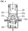
- Figure 4 is an enlarged cross-sectional elevation of the pressure regulator of this embodiment.
- the illustrated fuel supply apparatus includes a filter element support wall 6a which supports the filter medium of the filter element 6 and separates fuel which has been filtered from unfiltered fuel within the main housing 5.
- the element support wall 6a is made from an electrically conducting resin, and it acts as a conductor for dissipating static electricity which is generated during filtration of the fuel.
- the fuel supply apparatus also includes an upper housing 11 which is made of an electrically conducting resin and is joined to the main housing 5 by solvent bonding or other suitable method along a joining surface 12.
- a check valve 9 is provided in the upper housing 11 in a location which communicates with the outlet 5b of the main housing 5.
- the element support wall 6a which is also subjected to solvent bonding, forms a fuel passage communicating with the check valve 9.
- the element support wall 6a is electrically connected to the upper housing 11, so static electricity can be dissipated through the upper housing 11.
- the fuel supply apparatus can be mounted in an opening in the top of the fuel tank 1 by means of the flange of the cover 13.
- the fuel pump 2 is supported by a pump holder 15 which fits over the lower end of the main housing 5.
- One or more terminals such as a power supply terminal connected to the fuel pump 2, a grounding terminal connected to the upper housing 11, and a connecting terminal for an unillustrated fuel gauge may be mounted atop the cover 13.
- a fuel supply passage 8 including a nipple 8a for supplying fuel to an unillustrated engine extends from the top of the cover 13.
- the pump holder 15 supports a pressure regulator 20.
- a vibration absorber 16 made of rubber or other resilient material may be disposed between the pump holder 15 and the lower end of the fuel pump 2 to absorb vibrations of the fuel pump 2.
- the vibration absorber 16 has an opening in its lower end through which fuel can pass between the intake filter 3 and the inlet of the fuel pump 2.
- a bush 14 may be provided on the discharge port of the fuel pump 2 and around the check valve 9.
- the fuel pump 2 is eccentrically disposed with respect to the inner cylindrical wall of the main housing 5, and the pressure regulator 20 is installed at a branch hole 5c at the bottom of the main housing 5.
- the branch hole 5c is located on the side of the main housing 5 where the gap between the inner wall of the main housing 5 and the fuel pump 2 is largest.
- the branch hole 5c communicates with a space for unfiltered liquid on the upstream side of the filter element 6 at the bottom of the interior of the main housing 5.
- the pressure regulator 20 is not restricted to any particular type.
- a pressure regulator like the one illustrated in Figure 11 can be employed.
- the pressure regulator 20 in the present embodiment communicates with the upstream side of the filter element 6, it can have a simpler, easier to manufacture structure than the pressure regulator 10 of Figure 11.
- Figure 4 illustrates one example of a suitable structure for the pressure regulator 20. It includes a cylindrical valve 20b provided at the center of a diaphragm 20a. The cylindrical valve 20b is urged into contact with a spherical valve seat 20c by a back pressure spring 20e disposed between the valve 20b and the bottom of a tubular housing of the pressure regulator 20.
- valve seat 20c is secured by welding or other suitable method to a valve seat holder 20d which is secured to the housing of the pressure regulator 20.
- a connecting passage 20f for providing fluid communication between the inlet of the pressure regulator 20 (at the upper end of the pressure regulator 20) and the outlet thereof (at the lower end) is formed in the valve seat holder 20d.
- FIG 3 is a schematic illustration of the embodiment of Figure 1. This figure illustrates that the pressure regulator 20 is disposed on the upstream side of the filter element 6 and the check valve 9 instead of on the downstream side as in the apparatus illustrated in Figure 10.
- FIG. 1 - 4 operates in the following manner.
- gasoline or other liquid fuel is sucked from the interior of the fuel tank 1 by the fuel pump 2 through the intake filter 3, which removes coarse contaminants.
- the fuel is pressurized by the fuel pump 2 and discharged to the interior of the fuel filter unit 4 on the upstream side of the filter element 6.
- the pressure regulator 20 communicates with the upstream side of the filter element 6, so only fuel which is actually required by the unillustrated engine passes through the filter element 6 for the removal of fine contaminants, and fuel which is not required by the engine is discharged into the fuel tank 1 through the pressure regulator 20.
- Fuel which passes through the filter element 6 passes through the check valve 9 and into the fuel supply passage 8 for supply to the engine.
- the pressure within the fuel filter unit 4 is maintained in a prescribed range by the pressure regulator 20, which discharges excess fuel to inside the fuel tank 1 when the pressure in the fuel filter unit 4 exceeds a prescribed level due to an increase in the output of the fuel pump 2 or a decrease in fuel consumption by the engine.
- the filter element 6 can have a smaller filtration surface area than the filter element 6 in the apparatus of Figure 9, so the filter element 6 can be reduced in size, permitting a reduction in the overall size of the fuel supply apparatus.
- the fuel supply apparatus of this embodiment can further be minimized.
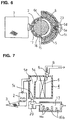
- Figures 5 - 8 illustrate another embodiment of a fuel supply apparatus according to the present invention.
- Figure 5 is a cross-sectional elevation of this embodiment
- Figure 6 is a cross-sectional view taken along line 6-6 of Figure 5
- Figure 7 is a schematic illustration of this embodiment
- Figure 8 is an enlarged perspective view of the vibration absorber of this embodiment.
- the overall structure of this embodiment is similar to that of the preceding embodiment, so only differences between the two embodiments will be described.
- this embodiment instead of fuel which passes through the outlet of the pressure regulator 20 being discharged directly into the fuel tank 1, it is first introduced into a sedimentation flow path 17 in which contaminant particles contained in the fuel can settle out.
- the sedimentation flow path 17 is formed between the outer periphery of the fuel pump 2 and the inner peripheral wall of the pump holder 15 and between the upper portion of the vibration absorber 16 and the lower end surface 5f of the main housing 5.
- Figure 8 illustrates an example of the shape of the vibration absorber 16 in this embodiment. It is a generally cup-shaped member with a crenelated upper end including a plurality of projections 16a spaced around the circumference of the vibration absorber 16 and a plurality of recesses 16b each disposed between two of the projections 16a and defining a groove for holding sediment which settles out of fuel flowing through the sedimentation flow path 17.
- One of the projections 16a is elongated and extends to the lower end surface 5f of the main housing 5 and defines a partition which separates the inlet and the outlet of the sedimentation flow path 17 from each other.
- the remaining projections 16a are shorter and do not extend to the lower end surface 5f of the main housing 5 so that fuel can flow along the space between the upper ends of these shorter projections 16a and the lower end surface 5f.
- a passage which communicates between the intake filter 3 and the inlet of the fuel pump 2 is formed in the bottom of the vibration absorber 16.
- the inlet of the sedimentation flow path 17 communicates with the outlet of the pressure regulator 20, and the outlet of the sedimentation flow path 17 is defined by a hole which is formed in a suitable location in a wall of the pump holder 15 which communicates with the interior of the fuel tank 1.
- the vibration absorber 16 which is made of a resilient material, is elastically compressed between the inner surface of the pump holder 15 and the outer surface of the fuel pump 2, so it forms a seal against the pump holder 15 and the fuel pump 2 along the length of the sedimentation flow path 17 so that fuel can enter and leave the sedimentation flow path 17 only through the inlet and outlet thereof.
- Figure 9 is a cross-sectional view of another vibration absorber 116 for defining a sedimentation flow path 117 that can be used instead of the vibration absorber 16 of Figure 5
- Figure 10 is an enlarged fragmental sectional view of the sedimentation flow path 117 shown in Figure 9
- Figure 11 is a sectional side view taken along line 11 - 11 of Figure 9.
- the vibration absorber 116 illustrated in Figure 9-11 comprises a vertically extending partition wall 116a having an upper end that abuts against a bottom surface 105f of the main housing 105 to vertically partition and define an inlet 117b and an outlet 117c of the sedimentation flow path 117.
- a number of fins 116b are disposed to extend from the inner periphery of the outer wall extending from the vibration absorber 116 into the sedimentation flow path 117 and in the direction perpendicular to that of the fuel flow within the sedimentation flow path 117 and the fins 116b define substantially cylindrical vortex spaces 117a between them.
- Each of the vortex spaces 117a has at its bottom end a blind hole 116c which is beveled at its open end.
- the inlet 117b of the sedimentation flow path 117 communicates with the discharge port of the pressure regulator 20.
- the outlet 117c of the sedimentation flow path 117 is defined by a communication hole formed at a suitable position in the wall of the pump holder 15 to open to the interior of the fuel tank 1.
- the sedimentation flow path 117 is substantially hermetically closed except for the inlet 117b and outlet 117c by fitting the vibration absorber 116 between the fuel pump 2, the pump holder 15 and the main housing 5 in a slightly elastically compressed state.
- the fuel which is actually supplied to the engine passes through the filter element 6 and has fine contaminants removed from it.
- excess fuel which is not supplied to the engine is discharged into the fuel tank 1 by the pressure regulator 20 without having passed through filter element 6, since the pressure regulator 20 communicates with the upstream side of the filter element 6.
- the fuel pump 2 When the fuel pump 2 employs a direct current motor as a drive source, powder caused by abrasion of the brushes and the commutator of the motor is frequently generated, and this powder is introduced as contamination into the fuel passing through the fuel pump 2.
- the amount of the contaminant powder present in the fuel which is not supplied to the engine increases with the length of operation of the fuel pump 2.
- the contaminant powder circulates from the fuel pump 2 to the fuel filter unit 4 to the pressure regulator 20 to the interior of the fuel tank 1 to the intake filter 3 and back to the fuel pump 2.
- the contaminant powder can be the cause of problems such as clogging of the intake filter 3, a decrease in the sealing ability of the pressure regulator 20, and an increase in the rotational resistance of the pump 2.
- the amount of contaminant powder present in the fuel circulating through the fuel supply apparatus is decreased by the sedimentation flow path 17.
- Powder formed by the abrasion of the brushes and the commutator of the motor of the fuel pump 2 has a higher specific gravity than the fuel in which it is contained, which is typically gasoline or similar liquid. Therefore, when fuel containing the contaminant powder is discharged from the pressure regulator 20 and introduced into the sedimentation flow path 17 illustrated in Figures 5 - 8, where the flow speed of the fuel is reduced, the contaminant powder settles out of the fuel within the sedimentation flow path 17 and collects as sediment in the recesses 16b of the vibration absorber 16 instead of being discharged into the fuel tank 1.
- vortex spaces 117a are defined by the fins 116b that extend from the vibration absorber 116 and the blind holes 16c are formed into the surfaces of the vibration absorber 116 in the embodiment shown in Figures 9 - 11, similar vortex spaces and blind holes may equally be defined in the inner circumferential surface of the pump holder 15.
- sedimentation flow path 17 shown in Figures 5 - 8 or the sedimentation flow path 117 shown in Figures 9 - 11 Another benefit of the sedimentation flow path 17 shown in Figures 5 - 8 or the sedimentation flow path 117 shown in Figures 9 - 11 is that since the fuel discharged from the pressure regulator 20 is not introduced directly into the fuel tank 1 but is introduced into the fuel tank 1 through the sedimentation flow path 17 or 117, the discharge noise of the pressure regulator 20 can be decreased.
- the embodiment of Figures 5 - 8 may further include a connecting pipe 5d which extends vertically within the main housing 5 along the outer wall thereof between the upper portion of the main housing 5 and the branch hole 5c.
- the interior of the connecting pipe 5d defines a connecting passage 5e which communicates between the upper portion of the main housing 5 and the branch hole 5c.
- flow to the pressure regulator 20 branches off from other flow within the main housing 5 at the upper portion of the main housing 5.
- the lower end of the connecting pipe 5d surrounds the branch hole 5c so that fuel within the main housing 5 can enter the branch hole 5c only by passing through the connecting pipe 5d.
- fuel which is discharged from the fuel pump 2 may contain particulate contaminants such as powder caused by abrasion in the motor of the fuel pump 2.
- the pressure regulator 20 When the pressure regulator 20 is in a closed state, the contaminant powder in fuel which is introduced into the pressure regulator 20 may become caught between the opposing surfaces of the valve 20b and the valve seat 20c, preventing intimate contact between the opposing surfaces and producing a decrease in the sealing ability of the pressure regulator 20. This decrease in sealing ability may allow fuel to leak out of the main housing 5 through the pressure regulator 20.
- fuel within the main housing 20 can only enter the pressure regulator 20 via the connecting pipe 5d which extends to the upper portion of the main housing 5. Therefore, even if fuel leaks from the pressure regulator 20 when an engine connected to the fuel supply apparatus is stopped, the main housing 5 as a whole will not run dry, since fuel in the portions of the main housing 5 outside of the connecting pipe 5d is prevented by the connecting pipe 5d from flowing into the pressure regulator 20. Therefore, the engine can be restarted without delay and without the introduction of large amounts of air into the engine.
- the pressure regulator 20 can have a simple valve structure which enables the pressure regulator 20 to be economical and compact.
Landscapes
- Engineering & Computer Science (AREA)
- Chemical & Material Sciences (AREA)
- Combustion & Propulsion (AREA)
- Mechanical Engineering (AREA)
- General Engineering & Computer Science (AREA)
- Chemical Kinetics & Catalysis (AREA)
- Cooling, Air Intake And Gas Exhaust, And Fuel Tank Arrangements In Propulsion Units (AREA)
- Structures Of Non-Positive Displacement Pumps (AREA)
- Fuel-Injection Apparatus (AREA)
Applications Claiming Priority (4)
| Application Number | Priority Date | Filing Date | Title |
|---|---|---|---|
| JP2000270265 | 2000-09-06 | ||
| JP2000270265 | 2000-09-06 | ||
| JP2001075873A JP4374789B2 (ja) | 2000-09-06 | 2001-03-16 | 燃料供給装置 |
| JP2001075873 | 2001-03-16 |
Publications (2)
| Publication Number | Publication Date |
|---|---|
| EP1186772A2 true EP1186772A2 (de) | 2002-03-13 |
| EP1186772A3 EP1186772A3 (de) | 2003-01-02 |
Family
ID=26599363
Family Applications (1)
| Application Number | Title | Priority Date | Filing Date |
|---|---|---|---|
| EP01120705A Withdrawn EP1186772A3 (de) | 2000-09-06 | 2001-09-04 | In einem Behälter angeordnete Brennstoffversorgungsvorrichtung |
Country Status (5)
| Country | Link |
|---|---|
| US (1) | US6520163B2 (de) |
| EP (1) | EP1186772A3 (de) |
| JP (1) | JP4374789B2 (de) |
| CN (1) | CN1209555C (de) |
| TW (1) | TW550337B (de) |
Cited By (7)
| Publication number | Priority date | Publication date | Assignee | Title |
|---|---|---|---|---|
| FR2849115A1 (fr) * | 2002-12-20 | 2004-06-25 | Siemens Vdo Automotive Corp | Module de pompe comportant un regulateur de pression |
| EP1388664A3 (de) * | 2002-08-05 | 2005-04-27 | Denso Corporation | Pumpenmodul |
| WO2005108146A1 (de) * | 2004-05-04 | 2005-11-17 | Robert Bosch Gmbh | Vorrichtung zum fördern von kraftstoff aus einem vorratsbehälter zu einer brennkraftmaschine |
| WO2006111435A1 (de) * | 2005-04-21 | 2006-10-26 | Robert Bosch Gmbh | Vorrichtung zum fördern von kraftstoff aus einem kraftstofftank zur brennkraftmaschine eines kraftfahrzeuges |
| EP1740820A4 (de) * | 2004-04-30 | 2008-02-20 | Int Engine Intellectual Prop | Kraftstoffsystem |
| EP2003322A3 (de) * | 2007-06-15 | 2009-04-15 | TI Automotive (Neuss) GmbH | Kraftstoffpumpe mit elektrisch kommutiertem Motor |
| EP2161440A3 (de) * | 2008-09-05 | 2011-09-28 | Delphi Technologies, Inc. | Brennstoffmodul mit Durchlassaufwärtsstrom aus einem Regler |
Families Citing this family (39)
| Publication number | Priority date | Publication date | Assignee | Title |
|---|---|---|---|---|
| CN1208546C (zh) * | 2000-08-18 | 2005-06-29 | 三菱电机株式会社 | 燃料供给装置 |
| TW558605B (en) * | 2002-02-08 | 2003-10-21 | Mitsubishi Electric Corp | Fuel filter and fuel supply device |
| WO2003100246A1 (en) * | 2002-05-29 | 2003-12-04 | Mitsubishi Denki Kabushiki Kaisha | Fuel supply system and fuel pressure regulator |
| US7302938B2 (en) * | 2003-10-16 | 2007-12-04 | Ford Motor Company | Mechanical returnless fuel system |
| US6953026B2 (en) * | 2003-10-16 | 2005-10-11 | Visteon Global Technologies, Inc. | Pressure regulating valve for automotive fuel system |
| US20060000454A1 (en) * | 2004-07-02 | 2006-01-05 | Visteon Global Technologies, Inc. | In-tank fuel supply unit having long life filter |
| US7591250B2 (en) * | 2005-06-22 | 2009-09-22 | Continental Automotive Systems Us, Inc. | Pump retaining structure for fuel pump module |
| US7263980B2 (en) * | 2005-06-22 | 2007-09-04 | Siemens Vdo Automotive Corporation | Pump vapor deflector for fuel pump module assembly |
| JP4664800B2 (ja) * | 2005-10-27 | 2011-04-06 | 株式会社ケーヒン | 燃料ポンプユニット装置 |
| JP4670781B2 (ja) * | 2006-09-22 | 2011-04-13 | 株式会社デンソー | 燃料ポンプモジュール |
| US7228849B1 (en) * | 2006-09-29 | 2007-06-12 | Delphi Technologies, Inc. | Conical concave cap pressure relief valve |
| JP4613917B2 (ja) * | 2007-03-07 | 2011-01-19 | 三菱電機株式会社 | 燃料供給装置 |
| JP4693809B2 (ja) * | 2007-04-03 | 2011-06-01 | 三菱電機株式会社 | 燃料ポンプモジュール |
| US20090000844A1 (en) * | 2007-06-27 | 2009-01-01 | Jesus Castillo | Fuel module with quick disconnect cover for easy filter replacement |
| JP4939318B2 (ja) * | 2007-06-28 | 2012-05-23 | 三菱電機株式会社 | 車両用燃料供給装置 |
| JP2009144542A (ja) * | 2007-12-12 | 2009-07-02 | Aisan Ind Co Ltd | 燃料供給装置 |
| US8079479B2 (en) | 2008-01-18 | 2011-12-20 | Synerject, Llc | In-tank fuel delivery module having an accessible fuel filter |
| JP2009236006A (ja) * | 2008-03-27 | 2009-10-15 | Mitsubishi Electric Corp | 燃料供給装置 |
| JP2011102550A (ja) * | 2009-11-10 | 2011-05-26 | Denso Corp | 燃料供給装置 |
| JP5370091B2 (ja) * | 2009-11-12 | 2013-12-18 | 京三電機株式会社 | 燃料フィルタ装置 |
| US8360740B2 (en) * | 2010-02-12 | 2013-01-29 | Synerject, Llc | Integrated fuel delivery module and methods of manufacture |
| CA2770867C (en) | 2011-03-08 | 2018-11-06 | Synerject Llc | In-tank fluid transfer assembly |
| CN102359426A (zh) * | 2011-09-08 | 2012-02-22 | 力帆实业(集团)股份有限公司 | 电喷摩托车燃油供给系统 |
| GB2505700B (en) * | 2012-09-10 | 2020-02-12 | Tco As | Injection device |
| JP6095520B2 (ja) * | 2013-08-20 | 2017-03-15 | 三菱電機株式会社 | 燃料供給装置 |
| JP6318987B2 (ja) * | 2013-11-05 | 2018-05-09 | 株式会社デンソー | 燃料供給装置 |
| JP6354463B2 (ja) * | 2013-11-05 | 2018-07-11 | 株式会社デンソー | 燃料供給装置 |
| JP6248868B2 (ja) * | 2013-11-05 | 2017-12-20 | 株式会社デンソー | 燃料供給装置 |
| JP2015121139A (ja) * | 2013-12-24 | 2015-07-02 | 株式会社デンソー | 燃料ポンプモジュール |
| US9753443B2 (en) | 2014-04-21 | 2017-09-05 | Synerject Llc | Solenoid systems and methods for detecting length of travel |
| US9997287B2 (en) | 2014-06-06 | 2018-06-12 | Synerject Llc | Electromagnetic solenoids having controlled reluctance |
| WO2015191348A1 (en) | 2014-06-09 | 2015-12-17 | Synerject Llc | Methods and apparatus for cooling a solenoid coil of a solenoid pump |
| JP6192631B2 (ja) * | 2014-12-08 | 2017-09-06 | 株式会社ニフコ | リザーバカップ |
| US20170130648A1 (en) * | 2015-11-10 | 2017-05-11 | Illinois Tool Works Inc. | Fuel System Improvements with High Pressure Pump for Welder Generators |
| JP6665064B2 (ja) * | 2016-09-20 | 2020-03-13 | 愛三工業株式会社 | 圧力調整弁 |
| JP2018096282A (ja) * | 2016-12-13 | 2018-06-21 | 愛三工業株式会社 | 燃料供給装置 |
| CN108005821A (zh) * | 2017-12-29 | 2018-05-08 | 浙江双良汽车零部件有限公司 | 燃料输送系统 |
| CN109736985A (zh) * | 2019-03-27 | 2019-05-10 | 众恒汽车部件有限公司 | 高密封性的滤清器及燃油泵总成 |
| TWI728824B (zh) * | 2020-06-02 | 2021-05-21 | 帆宣系統科技股份有限公司 | 流體去靜電裝置 |
Citations (2)
| Publication number | Priority date | Publication date | Assignee | Title |
|---|---|---|---|---|
| JPH05215048A (ja) | 1992-02-04 | 1993-08-24 | Nippondenso Co Ltd | 燃料圧力調整装置 |
| JPH11241659A (ja) | 1998-02-25 | 1999-09-07 | Mitsubishi Electric Corp | 燃料供給装置 |
Family Cites Families (14)
| Publication number | Priority date | Publication date | Assignee | Title |
|---|---|---|---|---|
| DE4242242C2 (de) * | 1992-12-15 | 2003-04-30 | Bosch Gmbh Robert | Vorrichtung zum Versorgen der Brennkraftmaschine eines Kraftfahrzeuges mit in einem Vorratstank vorhandenem Kraftstoff |
| US5511957A (en) * | 1994-09-27 | 1996-04-30 | Walbro Corporation | High capacity fuel pump and filter combination |
| JPH08121282A (ja) | 1994-10-20 | 1996-05-14 | Nippondenso Co Ltd | 燃料供給装置 |
| JPH08210212A (ja) * | 1994-11-04 | 1996-08-20 | Nippondenso Co Ltd | 燃料供給装置 |
| WO1996014506A1 (en) * | 1994-11-04 | 1996-05-17 | Nippondenso Co., Ltd. | Fuel supply apparatus |
| JP3256972B2 (ja) * | 1995-02-03 | 2002-02-18 | 株式会社デンソー | 燃料供給装置 |
| JPH08218984A (ja) | 1995-02-09 | 1996-08-27 | Toyota Motor Corp | 内燃機関の燃料供給装置 |
| US5769061A (en) * | 1996-04-01 | 1998-06-23 | Denso Corporation | Fuel supply system having a suction filter in a sub-tank |
| JPH1047185A (ja) * | 1996-08-06 | 1998-02-17 | Aisan Ind Co Ltd | 内燃機関用燃料供給装置 |
| FR2768667B1 (fr) * | 1997-09-23 | 1999-12-03 | Bitron France | Dispositif de pompage et reservoir de carburant pour vehicule automobile equipe d'un tel dispositif |
| JP3509881B2 (ja) * | 1997-12-08 | 2004-03-22 | 三菱電機株式会社 | 燃料供給装置 |
| US5908020A (en) * | 1998-07-13 | 1999-06-01 | Uis, Inc. | Marine fuel pump and cooling system |
| CN1208546C (zh) * | 2000-08-18 | 2005-06-29 | 三菱电机株式会社 | 燃料供给装置 |
| JP4404546B2 (ja) * | 2000-08-18 | 2010-01-27 | 三菱電機株式会社 | 燃料供給装置 |
-
2001
- 2001-03-16 JP JP2001075873A patent/JP4374789B2/ja not_active Expired - Lifetime
- 2001-08-29 TW TW090121261A patent/TW550337B/zh not_active IP Right Cessation
- 2001-08-30 CN CNB011312726A patent/CN1209555C/zh not_active Expired - Fee Related
- 2001-08-31 US US09/942,989 patent/US6520163B2/en not_active Expired - Fee Related
- 2001-09-04 EP EP01120705A patent/EP1186772A3/de not_active Withdrawn
Patent Citations (2)
| Publication number | Priority date | Publication date | Assignee | Title |
|---|---|---|---|---|
| JPH05215048A (ja) | 1992-02-04 | 1993-08-24 | Nippondenso Co Ltd | 燃料圧力調整装置 |
| JPH11241659A (ja) | 1998-02-25 | 1999-09-07 | Mitsubishi Electric Corp | 燃料供給装置 |
Cited By (11)
| Publication number | Priority date | Publication date | Assignee | Title |
|---|---|---|---|---|
| EP1388664A3 (de) * | 2002-08-05 | 2005-04-27 | Denso Corporation | Pumpenmodul |
| US7306715B2 (en) | 2002-08-05 | 2007-12-11 | Denso Corporation | Pump module |
| FR2849115A1 (fr) * | 2002-12-20 | 2004-06-25 | Siemens Vdo Automotive Corp | Module de pompe comportant un regulateur de pression |
| EP1740820A4 (de) * | 2004-04-30 | 2008-02-20 | Int Engine Intellectual Prop | Kraftstoffsystem |
| WO2005108146A1 (de) * | 2004-05-04 | 2005-11-17 | Robert Bosch Gmbh | Vorrichtung zum fördern von kraftstoff aus einem vorratsbehälter zu einer brennkraftmaschine |
| CN100513222C (zh) * | 2004-05-04 | 2009-07-15 | 罗伯特·博世有限公司 | 用于将燃料从贮备容器输送到内燃机的装置 |
| US7765990B2 (en) | 2004-05-04 | 2010-08-03 | Robert Bosch Gmbh | Device for delivering fuel from a tank to an internal combustion engine |
| WO2006111435A1 (de) * | 2005-04-21 | 2006-10-26 | Robert Bosch Gmbh | Vorrichtung zum fördern von kraftstoff aus einem kraftstofftank zur brennkraftmaschine eines kraftfahrzeuges |
| EP2003322A3 (de) * | 2007-06-15 | 2009-04-15 | TI Automotive (Neuss) GmbH | Kraftstoffpumpe mit elektrisch kommutiertem Motor |
| US8157542B2 (en) | 2007-06-15 | 2012-04-17 | Ti Automotive (Neuss) Gmbh | Brushless motor fuel pump with control electronics arrangement |
| EP2161440A3 (de) * | 2008-09-05 | 2011-09-28 | Delphi Technologies, Inc. | Brennstoffmodul mit Durchlassaufwärtsstrom aus einem Regler |
Also Published As
| Publication number | Publication date |
|---|---|
| JP4374789B2 (ja) | 2009-12-02 |
| TW550337B (en) | 2003-09-01 |
| CN1342833A (zh) | 2002-04-03 |
| EP1186772A3 (de) | 2003-01-02 |
| CN1209555C (zh) | 2005-07-06 |
| US6520163B2 (en) | 2003-02-18 |
| JP2002155823A (ja) | 2002-05-31 |
| US20020026927A1 (en) | 2002-03-07 |
Similar Documents
| Publication | Publication Date | Title |
|---|---|---|
| US6520163B2 (en) | In-tank fuel supply apparatus | |
| JP5414483B2 (ja) | 燃料供給装置 | |
| US5992394A (en) | Fuel supply device housing pump and filter in sub-tank | |
| US7874817B2 (en) | Fuel pump assembly with a vapor purge passage arrangement for a fuel pump module | |
| US6029633A (en) | Passive fuel delivery module and suspension mechanism | |
| US20040020839A1 (en) | Pump module | |
| US6719539B1 (en) | Fuel feeder | |
| US5758627A (en) | Fuel filter for vehicle | |
| KR20080082424A (ko) | 연료 공급 장치 | |
| KR100288416B1 (ko) | 연료 필터 | |
| JP3956867B2 (ja) | 燃料供給装置 | |
| US7472693B2 (en) | Fuel feed apparatus having fuel pump and filter | |
| JPH1061519A (ja) | 燃料微孔フィルタを有する燃料圧送モジュール | |
| JPH11230076A (ja) | 燃料圧送ユニット | |
| JP4168602B2 (ja) | 船外機における燃料供給装置 | |
| KR20010033373A (ko) | 연료 공급 모듈 | |
| JP2009236006A (ja) | 燃料供給装置 | |
| CN108884797B (zh) | 压力调节器及燃料供给装置 | |
| CN112105435A (zh) | 用于清洁液态的流体的过滤器的过滤壳体的中间盖和滤芯以及过滤器和用途 | |
| JP5285057B2 (ja) | 燃料供給装置 | |
| KR100704347B1 (ko) | 전기펌프를 자동차 연료탱크 내에 장착하는 구조체, 및각각의 흡입필터 | |
| JP6804608B1 (ja) | 燃料供給装置 | |
| JP4329037B2 (ja) | 燃料供給装置 | |
| JP2010144594A (ja) | 燃料ポンプ | |
| JP2003201932A (ja) | 燃料供給装置 |
Legal Events
| Date | Code | Title | Description |
|---|---|---|---|
| PUAI | Public reference made under article 153(3) epc to a published international application that has entered the european phase |
Free format text: ORIGINAL CODE: 0009012 |
|
| AK | Designated contracting states |
Kind code of ref document: A2 Designated state(s): AT BE CH CY DE DK ES FI FR GB GR IE IT LI LU MC NL PT SE TR |
|
| AX | Request for extension of the european patent |
Free format text: AL;LT;LV;MK;RO;SI |
|
| PUAL | Search report despatched |
Free format text: ORIGINAL CODE: 0009013 |
|
| AK | Designated contracting states |
Kind code of ref document: A3 Designated state(s): AT BE CH CY DE DK ES FI FR GB GR IE IT LI LU MC NL PT SE TR |
|
| AX | Request for extension of the european patent |
Free format text: AL;LT;LV;MK;RO;SI |
|
| 17P | Request for examination filed |
Effective date: 20021218 |
|
| AKX | Designation fees paid |
Designated state(s): DE FR GB |
|
| RAP1 | Party data changed (applicant data changed or rights of an application transferred) |
Owner name: MITSUBISHI DENKI KABUSHIKI KAISHA |
|
| STAA | Information on the status of an ep patent application or granted ep patent |
Free format text: STATUS: THE APPLICATION HAS BEEN WITHDRAWN |
|
| 18W | Application withdrawn |
Effective date: 20071228 |