EP1186940A2 - Dispositif pour le contrôle de la lumière utilisant un cristal liquide et son procédé de fabrication - Google Patents
Dispositif pour le contrôle de la lumière utilisant un cristal liquide et son procédé de fabrication Download PDFInfo
- Publication number
- EP1186940A2 EP1186940A2 EP01121604A EP01121604A EP1186940A2 EP 1186940 A2 EP1186940 A2 EP 1186940A2 EP 01121604 A EP01121604 A EP 01121604A EP 01121604 A EP01121604 A EP 01121604A EP 1186940 A2 EP1186940 A2 EP 1186940A2
- Authority
- EP
- European Patent Office
- Prior art keywords
- alignment film
- light
- controlling device
- treated
- transparent
- Prior art date
- Legal status (The legal status is an assumption and is not a legal conclusion. Google has not performed a legal analysis and makes no representation as to the accuracy of the status listed.)
- Withdrawn
Links
Images



Classifications
-
- G—PHYSICS
- G02—OPTICS
- G02F—OPTICAL DEVICES OR ARRANGEMENTS FOR THE CONTROL OF LIGHT BY MODIFICATION OF THE OPTICAL PROPERTIES OF THE MEDIA OF THE ELEMENTS INVOLVED THEREIN; NON-LINEAR OPTICS; FREQUENCY-CHANGING OF LIGHT; OPTICAL LOGIC ELEMENTS; OPTICAL ANALOGUE/DIGITAL CONVERTERS
- G02F1/00—Devices or arrangements for the control of the intensity, colour, phase, polarisation or direction of light arriving from an independent light source, e.g. switching, gating or modulating; Non-linear optics
- G02F1/01—Devices or arrangements for the control of the intensity, colour, phase, polarisation or direction of light arriving from an independent light source, e.g. switching, gating or modulating; Non-linear optics for the control of the intensity, phase, polarisation or colour
- G02F1/13—Devices or arrangements for the control of the intensity, colour, phase, polarisation or direction of light arriving from an independent light source, e.g. switching, gating or modulating; Non-linear optics for the control of the intensity, phase, polarisation or colour based on liquid crystals, e.g. single liquid crystal display cells
- G02F1/133—Constructional arrangements; Operation of liquid crystal cells; Circuit arrangements
- G02F1/1333—Constructional arrangements; Manufacturing methods
- G02F1/1337—Surface-induced orientation of the liquid crystal molecules, e.g. by alignment layers
- G02F1/133753—Surface-induced orientation of the liquid crystal molecules, e.g. by alignment layers with different alignment orientations or pretilt angles on a same surface, e.g. for grey scale or improved viewing angle
-
- G—PHYSICS
- G02—OPTICS
- G02F—OPTICAL DEVICES OR ARRANGEMENTS FOR THE CONTROL OF LIGHT BY MODIFICATION OF THE OPTICAL PROPERTIES OF THE MEDIA OF THE ELEMENTS INVOLVED THEREIN; NON-LINEAR OPTICS; FREQUENCY-CHANGING OF LIGHT; OPTICAL LOGIC ELEMENTS; OPTICAL ANALOGUE/DIGITAL CONVERTERS
- G02F1/00—Devices or arrangements for the control of the intensity, colour, phase, polarisation or direction of light arriving from an independent light source, e.g. switching, gating or modulating; Non-linear optics
- G02F1/01—Devices or arrangements for the control of the intensity, colour, phase, polarisation or direction of light arriving from an independent light source, e.g. switching, gating or modulating; Non-linear optics for the control of the intensity, phase, polarisation or colour
- G02F1/13—Devices or arrangements for the control of the intensity, colour, phase, polarisation or direction of light arriving from an independent light source, e.g. switching, gating or modulating; Non-linear optics for the control of the intensity, phase, polarisation or colour based on liquid crystals, e.g. single liquid crystal display cells
- G02F1/133—Constructional arrangements; Operation of liquid crystal cells; Circuit arrangements
- G02F1/1333—Constructional arrangements; Manufacturing methods
- G02F1/1337—Surface-induced orientation of the liquid crystal molecules, e.g. by alignment layers
- G02F1/13378—Surface-induced orientation of the liquid crystal molecules, e.g. by alignment layers by treatment of the surface, e.g. embossing, rubbing or light irradiation
- G02F1/133788—Surface-induced orientation of the liquid crystal molecules, e.g. by alignment layers by treatment of the surface, e.g. embossing, rubbing or light irradiation by light irradiation, e.g. linearly polarised light photo-polymerisation
-
- G—PHYSICS
- G02—OPTICS
- G02F—OPTICAL DEVICES OR ARRANGEMENTS FOR THE CONTROL OF LIGHT BY MODIFICATION OF THE OPTICAL PROPERTIES OF THE MEDIA OF THE ELEMENTS INVOLVED THEREIN; NON-LINEAR OPTICS; FREQUENCY-CHANGING OF LIGHT; OPTICAL LOGIC ELEMENTS; OPTICAL ANALOGUE/DIGITAL CONVERTERS
- G02F1/00—Devices or arrangements for the control of the intensity, colour, phase, polarisation or direction of light arriving from an independent light source, e.g. switching, gating or modulating; Non-linear optics
- G02F1/01—Devices or arrangements for the control of the intensity, colour, phase, polarisation or direction of light arriving from an independent light source, e.g. switching, gating or modulating; Non-linear optics for the control of the intensity, phase, polarisation or colour
- G02F1/13—Devices or arrangements for the control of the intensity, colour, phase, polarisation or direction of light arriving from an independent light source, e.g. switching, gating or modulating; Non-linear optics for the control of the intensity, phase, polarisation or colour based on liquid crystals, e.g. single liquid crystal display cells
- G02F1/133—Constructional arrangements; Operation of liquid crystal cells; Circuit arrangements
- G02F1/1333—Constructional arrangements; Manufacturing methods
- G02F1/1337—Surface-induced orientation of the liquid crystal molecules, e.g. by alignment layers
- G02F1/133753—Surface-induced orientation of the liquid crystal molecules, e.g. by alignment layers with different alignment orientations or pretilt angles on a same surface, e.g. for grey scale or improved viewing angle
- G02F1/133757—Surface-induced orientation of the liquid crystal molecules, e.g. by alignment layers with different alignment orientations or pretilt angles on a same surface, e.g. for grey scale or improved viewing angle with different alignment orientations
-
- G—PHYSICS
- G02—OPTICS
- G02F—OPTICAL DEVICES OR ARRANGEMENTS FOR THE CONTROL OF LIGHT BY MODIFICATION OF THE OPTICAL PROPERTIES OF THE MEDIA OF THE ELEMENTS INVOLVED THEREIN; NON-LINEAR OPTICS; FREQUENCY-CHANGING OF LIGHT; OPTICAL LOGIC ELEMENTS; OPTICAL ANALOGUE/DIGITAL CONVERTERS
- G02F1/00—Devices or arrangements for the control of the intensity, colour, phase, polarisation or direction of light arriving from an independent light source, e.g. switching, gating or modulating; Non-linear optics
- G02F1/29—Devices or arrangements for the control of the intensity, colour, phase, polarisation or direction of light arriving from an independent light source, e.g. switching, gating or modulating; Non-linear optics for the control of the position or the direction of light beams, i.e. deflection
Definitions
- the present invention relates to a light controlling device using liquid crystal and a method of producing the same and an optical alignment-treatment for an alignment film.
- a light controlling device using liquid crystal is referred to simply as "light controlling device" in this specification.
- Each of the light controlling device includes a cell container and liquid crystal filled in the cell container.
- the cell container includes two transparent substrates arranged opposing each other with a gap therebetween. Disposed on one surface of each transparent substrate are a transparent electrode pattern and an alignment film.
- a rubbing process is beforehand conducted in general for the alignment film.
- a multi-domain treatment is conducted for the alignment film.
- the alignment film is subdivided into small partitions classified into groups and alignment treatments are conducted for the respective groups such that each group has different alignment direction to each other.
- a mask of a predetermined shape is in general formed by photolithography to cover the partitions of particular groups.
- a rubbing process or an optical alignment-treatment for aligning the molecules along a predetermined direction is conducted for the remaining partitions of groups not covered with the mask.
- a mask of another predetermined shape is formed by photolithography.
- the refractive index of liquid crystal changes between a direction parallel to and a direction vertical to a longitudinal direction of molecule of the liquid crystal. Therefore, the refractive index of liquid crystal layer is influenced by the direction of light incident thereto.
- the apparent refractive index of liquid crystal layer means an effective (actual) refractive index of liquid crystal layer and is influenced by the direction of the incident light.
- the alignment-treatment by rubbing process produces an alignment film which aligns molecules of the liquid crystal in uniaxial direction. Therefore, in a light controlling device including an alignment film treated with the rubbing process, the apparent refractive index of liquid crystal layer is easily influenced by the direction of light incident thereto.
- the apparent refractive index of liquid crystal layer is less influenced by the direction of light incident thereto.
- this light controlling device has non-negligible discontinuity in the alignment direction of molecules of the liquid crystal at boundary between one partition and another partition in the alignment film.
- Another object of the present invention is to provide a method of producing a light controlling device capable of easily conducting a desired light controlling operation.
- Still another object of the present invention is to provide a method of optical alignment-treatment for facilitating to obtain an alignment film which can uniformly align molecules of liquid crystal in any azimuth direction in a plane.
- a light controlling device comprising (i) a cell container, comprising a first transparent substrate and a second transparent substrate, said first and second transparent substrates opposing each other with a gap therebetween; a transparent electrode pattern and an alignment film formed on an inside surface of each said substrate, at least one of said alignment films being a treated alignment film; and (ii) liquid crystal filled in said cell container, said liquid crystal including liquid-crystal molecules uniformly aligned, when voltages are not applied to said transparent electrode patterns respectively formed on said first and second transparent substrates, in any direction of azimuth in a plane at the surface of said alignment film on said first transparent substrate and in a plane at the surface of said alignment film on said second transparent substrate.
- a method of producing a light controlling device comprising the steps of: preparing a transparent substrate having one surface on which a transparent electrode pattern and a non-treated alignment film of which surface properties change by light radiated thereonto are formed; arranging a photo mask including a slit-shaped light transmission section and a light source on an outside of said non-treated alignment film; radiating light, with a relative positional relationship between said photo mask and said light source kept fixed, via said light transmission section onto said non-treated alignment film with a constant oblique angle of incidence of light while rotating said non-treated alignment film relative to said photo mask, conducting thereby an optical alignment-treatment for said non-treated alignment film, and resultantly obtaining a treated alignment film thus processed; assembling a cell container using said transparent substrate having said treated alignment film; and filling said cell container with liquid crystal.
- a method of optical alignment-treatment comprising the steps of: arranging a photo mask including a slit-shaped light transmission section and a light source on an outside of a non-treated alignment film of which surface properties change by light radiated thereonto; and radiating light, with a relative positional relationship between said photo mask and said light source kept fixed, via said light transmission section onto said non-treated alignment film with a constant oblique angle of incidence of light while rotating said non-treated alignment film relative to said photo mask and conducting thereby an optical alignment-treatment for said non-treated alignment film.
- the apparent refractive index of the liquid crystal layer can be kept substantially fixed regardless of an incidence angle of light incident thereto.
- molecules of the liquid crystal are aligned, for example, radially or concentrically in the plane.
- optical alignment-treatment it is possible to produce an alignment film which radially or concentrically aligns the liquid-crystal molecules in a plane at the surface.
- the apparent refractive index of liquid crystal layer is less influenced by the direction of light incident thereto. This leads to a light controlling device to easily control light in a desired way.
- a cell container of a light controlling device includes a first alignment film for which the optical alignment-treatment is conducted and a second alignment film for which any alignment-treatment is not conducted and the cell container is filled with liquid crystal to which a chiral agent is added, there can be produced a light controlling device in which molecules of the liquid crystal are aligned in any azimuth direction in a plane at the surface of the first alignment film and in a plane at the surface of the second alignment film.
- a film made of an alignment material for which an alignment-treatment has been conducted is called “a treated alignment film” and a film made of an alignment material for which any alignment treatment is not conducted is called “a non-treated alignment film”.
- a slit-shaped light transmission section is as follows.
- a light shielding film having a slit is formed on a transparent base material, a region of the transparent base material exposed in the slit forms the slit-shaped light transmission section.
- a light transmission section implemented by a slit formed in a predetermined location of the light shielding material also forms the slit-shaped light transmission section.
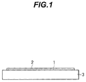
- Figs. 1, 2A, 2B, 3, 4, and 5 are diagram for explaining a method of producing a light controlling device according to an embodiment.
- a transparent electrode pattern 1 and a non-treated alignment film 2 are formed on one surface of a transparent substrate 3.
- the transparent electrode pattern 1 is formed in a desired contour according to, for example, a kind of a light controlling device to be produced.
- the transparent electrode pattern 1 can be formed, for example, by one transparent electrode which covers a predetermined area of one surface of the transparent substrate 3 or by concentrically arranging many annular transparent electrodes having mutually different diameters.
- the transparent electrode pattern 1 can be formed, for example, by arranging many circular transparent electrodes in a matrix form.
- the transparent electrode pattern 1 can be formed, for example, by forming many transparent electrodes on one surface of the transparent substrate 3, leaving a central section of the surface of the transparent substrate 3 as an area to form a treated alignment film.
- the transparent electrode pattern 1 is formed using transparent electrode materials such as indium tin oxide (ITO), zinc oxide, tin oxide, and indium oxide, and the like, or thin film of metal such as gold and the like.
- transparent electrode materials such as indium tin oxide (ITO), zinc oxide, tin oxide, and indium oxide, and the like, or thin film of metal such as gold and the like.
- the non-treated alignment film 2 is a film formed using an alignment material of which surface properties are changeable by radiation of light.
- the change of the surface properties is caused, when the film 2 is made of organic polymer, by phenomena such as (1) disconnection of a main chain or side chains of the polymer, (2) displacement of a direction of the side chain, and (3) cross-linking.
- the materials of the film 2 include, for example, polyvinyl cinnamate (PVC), polyimide (e.g., SE-610, SE-7792, or the like manufactured by Nissan Chemical Industries Ltd.), polysilane modified with cinnamoyl group, and organic material modified with chalcone group to enhance photodimerization by radiation of light having a long wavelength.
- the non-treated alignment film 2 is formed in a desired shape such as a circular or rectangular shape by spin coating, offset printing, or the like.
- pre-baking and/or post-baking are/is carried out when necessary.
- a location in which the non-treated alignment film 2 is formed is appropriately selected according to a kind or the like of the light controlling device to be produced.
- the non-treated alignment film 2 is formed to cover the transparent electrode pattern 1 as shown in Fig. 1.
- the non-treated alignment film 2 is directly formed in a predetermined location on one surface of the transparent substrate 3.
- the transparent electrode pattern 1 is not interposed between the film 2 and the transparent substrate 3.
- Film thickness of the non-treated alignment film 2 can be appropriately selected in a range from about 0.001 micrometer ( ⁇ m) to about 0.2 ⁇ m.
- the film thickness of the film 2 favorably ranges from about 0.01 ⁇ m to 0.1 ⁇ m.
- the transparent substrate 3 itself, not including the transparent electrode pattern 1 and the non-treated alignment film 2, is formed using a plate or a film made of transparent glass, transparent resin, transparent ceramic, or the like, which have a desired light transmittance corresponding to use or the like of the light controlling device to be produced. It is favorable that the substrate 3 is thin, desirably one millimeter (mm) or less, and more desirably 0.3 mm or less.
- an optical alignment-treatment is conducted for the film 2.
- Figs. 2A and 2B show a method of executing the optical alignment-treatment.
- a photo mask 6 with a slit-shaped light transmission section 5 formed therein and a light source, not shown, are placed outside of the non-treated alignment film 2.
- predetermined light L is radiated from the light source via the light transmission section 5 onto the non-treated alignment film 2 with a fixed, inclined angle of incidence while the non-treated alignment film 2 being rotated relative to the photo mask 6.
- the optical alignment-treatment is conducted for the non-treated alignment film 2. Resultantly, a treated alignment film is obtained.
- the light L obliquely enters the film 2 with incidence angle ⁇ 1.
- the light L is substantially parallel to a central line of the light transmission section 5 in its longitudinal direction when viewed in a front view.
- the light L is a polarized light or non-polarized light with a predetermined wavelength depending on a material of the non-treated alignment film 2.
- the transparent substrate 3 is attached onto a rotary shaft 7 such that the non-treated alignment film 2 faces upward in an inclined state and is inclined by an angle ⁇ 1 relative to a plane in which the incident angle of the light L is 0 degree (°), and the substrate 3 is rotated in a direction of an arrow mark A.
- the photo mask 6 is fixed to be substantially parallel to the transparent substrate 3.
- An end point 5a of the light transmission section 5 is placed in an extent of a central line B of the rotary shaft 7. Therefore, when the rotary shaft 7 rotates, the light transmission section 5 rotates relative to the non-treated alignment film 2.
- the section 5 rotates about the end point 5a.
- the light transmission section 5 need has a line width equal to or larger than the wavelength of the light L used in the alignment-treatment. Length of the section 5 is appropriately selected according to a size and a shape of the region to be treated in the non-treated alignment film 2, a distance between the photo mask 6 and the non-treated alignment film 2, the incident angle ⁇ 1 of the light L, and the like.
- the light transmission section 5 favorably has a contour of a sector, as view in plan, as shown in Fig. 2A to obtain a treated alignment film to radially align liquid-crystal molecules.
- the section 5 may be in a shape, as view in plan, of a slit, a rectangle, an ellipse, or shapeless.
- the light transmission section 5 can be, for example, in the rectangular shape.
- the section 5 has the sector shape, it is desirable that the section has a line width equal to or larger than the wavelength of the light L also at the end point 5a as the center of the relative rotational movement. Therefore, the shape, as viewed in plan, of the section 5 cannot be exactly the shape of a sector depending on cases.
- the light transparent section 5 of following type is also called "a light transparent section 5 of a sector shape”.
- the end point 5a of the section 5 has a line width equal to or larger than the wavelength of the light L and hence the shape, as viewed in plan, of the section 5 is not exactly a sector. However, if two sides each of which through, as viewed in plan, the end point 5a are extended to outside of the end point 5a, the light transmission section 5 can be in the shape, as viewed in plan, of an exact sector.
- the sector favorably has a central angle ⁇ 2 ranging from about 0.1° to about 45°, more favorably, from about 0.5° to about 5°.
- Figs. 3A and 3B are conceptual diagrams of a shaded light transmission section.
- the light transmission section 15 of Fig. 3A is a light transmission section formed, when a light shielding film 10 having a sector-shaped slit 10a is formed on a transparent base material 11, by using the transparent base material 11 exposed in the slit 10a.
- the light transmission section 15 is colored such that the quantity of transmission light of the section 15 increases or decreases in a direction from a center of the sector-shaped slit 10a to an outer end thereof.
- the colored area is smudged. Gradation of the smudging indicates that of the color.
- a light transmission section 25 of Fig. 3B is also formed, when a light shielding film 20 having a sector-shaped slit 20a is formed on a transparent base material 21, by using the transparent base material 21 exposed in the slit 20a.
- the section 25 includes many shading plates 22 disposed on its rear surface (placed on the side of the non-treated alignment film 2 when used).
- shading plates 22 are composed, as a whole, of masks of which the light transmission factor continuously ranging from several percent to 100 percent.
- the quantity of transmission light decreases in a direction from the center of the sector-shaped slit 20a to an outer end thereof.
- the wavelength and intensity of the light L used for the optical alignment-treatment are appropriately selected depending on various factors such as a material of the non-treated alignment film 2, the inclination angle of the transparent substrate 3, the rotary speed of the substrate 3, and materials of the liquid crystal used for the light controlling device to be produced.
- the incidence angle ⁇ 1 of the light L can be selected in a range from about 5° to about 85°.
- the angle ⁇ 1 favorably ranges from about 30° to about 80°, more favorably from about 30° to about 60°.
- an alignment film produced by conducting an optical alignment-treatment for a non-treated alignment film 2 is referred to as "a treated alignment film 2a" and an area of the alignment film 2a in which the alignment treatment has been actually conducted is referred to as "optically treated section”.
- a cell container is assembled using the transparent substrate 3 with the treated alignment film 2a obtained by conducting the optical alignment-treatment for the non-treated alignment film 2.
- Fig. 4 schematically shows a cross section of the cell container assembled as above.
- two transparent substrates 3, 3 each of which includes the treated alignment film 2a obtained by conducting the optical alignment-treatment for the non-treated alignment film 2 are attached to each other using seal members (e.g. adhesive) 11 disposed on edge sections of either one of the substrates 3, 3 with a predetermined cell thickness kept therebetween to resultantly assemble a cell container 30.
- seal members e.g. adhesive
- Each treated alignment film 2a is placed inside the cell container 30.
- projections of the center of rotation of the slit-shaped light transmission section 5 used in the optical alignment-treatment overlap each other in a plan view.
- the cell container 30 may be assembled using one transparent substrate 3 having a treated alignment film 2a and the other transparent substrate 3 having a non-treated alignment film 2.
- liquid crystal 40 As shown in Fig. 5, by filling liquid crystal 40 in the cell container 30, a light controlling device 50 can be obtained. Various kinds of liquid crystal can be used.
- a light controlling device 50 By producing a light controlling device 50 with above-described manner, there can be obtained a light controlling device in which when each transparent electrode pattern 1 is not applied with a voltage, the liquid-crystal molecules at the surface of the optically treated section of the treated alignment film 2a are radially aligned in a plane.
- the liquid-crystal molecules are uniformly aligned in any azimuth direction in the plane at the surface of the optically treated section. Resultantly, in the area of the treated alignment film 2a included in the optically treated section in a plan view, anisotropy of the apparent refractive index of the liquid-crystal layer is improved. Therefore, by using the area as an effective operation area of the light controlling device 50, the apparent refractive index of the device 50 is less influenced by the direction of light incident thereto. Therefore, light can be easily and desirably controlled.
- the area of the treated alignment film 2a included in the optically treated section in a plan view will be referred to as "effective operation area" of the light controlling device herebelow.
- the light controlling device of a first embodiment can be produced using the method of producing a light controlling device in the embodiment described above.
- the description below will be given by referring to the reference numerals of Figs. 1, 2A, 2B, 4, and 5.
- a transparent electrode pattern 1 is formed using a transparent electrode material covering the surface of the glass substrate.
- a 0.05 ⁇ m thick polyimide film SE-610 manufactured by Nissan Chemical Industries Ltd.
- the polyimide film is pre-baked for two minutes at 90°C and is then post-baked for 90 minutes at 220°C to resultantly obtain a non-treated alignment film 2.
- the optical alignment-treatment is conducted as shown in Figs. 2A and 2B to obtain a treated alignment film 2a.
- the light transmission section 5 used in the treatment has a sector in which the end point 5a is 0.5 ⁇ m wide, the string on the other end is 10 ⁇ m long, the radius of the section 5 is 200 ⁇ m long, and the center angle ⁇ 2 is about 2.7°.
- the light L used in the optical alignment-treatment is an ultraviolet ray.
- the light L is radiated onto the non-treated alignment film 2 with the incident angle ⁇ 1 set to 45°.
- the quantity of radiate light is selected such that light having a 315 nm wavelength radiated via the slit-shaped light transmission section 5 onto the non-treated alignment film 2 has an intensity of 100 mJ/m 2 .
- the glass substrate (transparent substrate 3) is rotated only once.
- the transparent substrates 3 are attached to each other using the seal members (e.g. adhesive) 11 as shown in Fig. 4 to assemble a cell container 30.
- the seal members e.g. adhesive
- the cell container 30 is then filled with liquid crystal 40 such as fluorine-containing nematic liquid crystal (e.g. ZLI-4792 manufactured by Merck Ltd.) or super-twisted nematic liquid crystal (e.g. ZLI-2293 manufactured by Merck Ltd.) as shown in Fig. 5 to obtain a light controlling device.
- liquid crystal 40 such as fluorine-containing nematic liquid crystal (e.g. ZLI-4792 manufactured by Merck Ltd.) or super-twisted nematic liquid crystal (e.g. ZLI-2293 manufactured by Merck Ltd.) as shown in Fig. 5 to obtain a light controlling device.
- the liquid crystal 40 does not contain the chiral agent.
- Fig. 6 schematically shows the state of alignment.
- each arrow mark indicates an alignment direction of liquid-crystal molecules.
- liquid-crystal molecules at the surface are radially aligned in a plane as a whole, centering on a position O.
- the position O is a projection, onto the treated alignment film 2a, of the center of rotation of the slit-shaped light transmission section 5 used in the optical alignment-treatment.
- Each liquid-crystal molecule at the surface is in a state slightly tilted with raising an outer side thereof.
- the liquid-crystal molecules have a pre-tilt angle of about 1°.
- each transparent electrode pattern 1 of the light controlling device 50 When a voltage is applied to each transparent electrode pattern 1 of the light controlling device 50, there does not occur any defect such as disclination line in the effective operation area. Therefore, it can be recognized that each liquid-crystal molecule rose in the direction of its pre-tilt angle in the effective operation area.
- the device 50 can be used, for example, as a liquid-crystal lens or a lens aberration compensator.
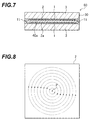
- Fig. 7 schematically shows a cross section of a light controlling device 60 of the embodiment.
- the same constituent components as those shown in Fig. 1 or 5 are assigned with the same reference numerals, and description thereof will be avoided.
- the optical controlling device 60 differs in structure from the optical controlling device 50 of the first embodiment in that a non-treated alignment film 2 is formed on one of the transparent substrates 3 of the cell container 30 and the cell container 30 is filled with liquid crystal 40a containing a chiral agent (e.g., S-811 or ZLI-3786 manufactured by Merck Ltd.). Excepting these points, the optical controlling device 60 is the same in structure as the optical controlling device 50 of the first embodiment.
- a chiral agent e.g., S-811 or ZLI-3786 manufactured by Merck Ltd.
- the chiral agent is added to the liquid crystal such that a ratio d/p between the cell thickness d of the light controlling device 60 and the chiral pitch p is 1/4. That is, the chiral agent is added so as to set the twist angle of the liquid crystal to 90°
- the liquid crystal 40a containing the chiral agent is filled in the cell container 30 in an isotropic state or in a nematic state. In the nematic state, defect of flow orientation remains in the liquid crystal 40a. Therefore, in a relatively short period of time after the injection of the liquid crystal 40a, the liquid crystal 40a is heated for about one hour at 150C°. The liquid crystal 40a is then gradually cooled for re-alignment.
- the state of alignment of liquid-crystal molecules in a plane at a surface of the optically treated section of the treated alignment film 2a is substantially the same as that of liquid-crystal molecules in a plane at the surface of the optically treated section of the treated alignment film 2a in the light controlling device 50 of the first embodiment.
- the state of alignment of liquid-crystal molecules in a plane at a surface of the non-treated alignment film 2 is considerably different from that of the liquid-crystal molecules in a plane at the surface of the treated alignment film 2a.
- Fig. 8 schematically shows the state of alignment of liquid-crystal molecules at the surface of the non-treated alignment film 2.
- Each arrow mark indicated by dotted lines indicates an alignment direction of the liquid-crystal molecules.
- liquid-crystal molecules at the surface are concentrically aligned about a point P of the non-treated alignment film 2 in a state in which each liquid-crystal molecule is relatively rotated 90° from an alignment direction of the liquid-crystal molecule at the surface of the treated alignment film 2a.
- the point P of the non-treated alignment film 2 shown in Fig. 8 overlaps, in a plan view, the position of the projection, onto the treated alignment film 2a, of the center of rotation of the slit-shaped light transmission section 5 used in the optical alignment-treatment to form the treated alignment film 2a.
- each transparent electrode pattern 1 of the light controlling device 60 When a voltage is applied to each transparent electrode pattern 1 of the light controlling device 60, defects such as a disclination line does not appear in the effective operation area. This implies that the each molecule of liquid crystal rose respectively fixed direction in the effective operation area.
- the device 60 can be used for the purposes as the light controlling device 50.
- the rising direction of the liquid-crystal molecules can be controlled without controlling the surface energy of the non-treated alignment film.
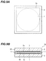
- Fig. 9A is a plan view schematically showing one of two transparent substrates 3 of the light controlling device 70 in the third embodiment.
- Fig. 9B schematically shows a cross section of the light controlling device 70.
- the light controlling device 70 of the third embodiment is a light controlling device which can be used as a liquid-crystal lens.
- each transparent electrode pattern 1 includes one circular transparent electrode.
- An overall upper surface of the treated alignment film 2a is an optically treated section.
- the light controlling device 70 is constituted in the same way as for the light controlling device 50 of the first embodiment.
- liquid-crystal molecules at the surface of the treated alignment film 2a of the light controlling device 50 liquid-crystal molecules at the surface of the optically treated section of the light controlling device 70 are radially aligned in a plane as a whole each of the liquid-crystal molecules is slightly tilted with raising an outer side thereof.
- an electric filed generated between the patterns 1 is represented by lines of electric force.
- a line of electric force from a center of one electrode pattern 1 to the other electrode pattern 1 is linearly drawn.
- lines of electric force between the electrode patterns 1 draw curves toward the outside. The curvature of the lines of electric force is stronger as the lines are drawing between the more peripheral positions of the electrode patterns 1.
- the strength of the electric filed generated between the electrode patterns 1 become weaker as the distance the pertinent line of electric force and the center of the electrode patterns 1 increases in a plan view.
- a non-uniform electric filed is formed between the electrode patterns 1.
- the light controlling device 70 can be used as a liquid-crystal lens having a variable focal distance.
- a treated alignment film 2a which can radially align the liquid-crystal molecules by continuously changing the pre-tilt thereof in a direction from the position O shown in Fig. 6 to the outside.
- the light controlling device in which the liquid-crystal molecules are thus aligned can be used as a liquid-crystal lens having a variable focal distance even when each transparent electrode pattern 1 is shaped into a rectangular.
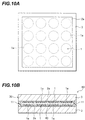
- Fig. 10A is a plan view schematically showing one of two transparent substrates 3 of the light controlling device 80 of the fourth embodiment.
- Fig. 10B schematically shows a cross section of the light controlling device 80.
- the light controlling device 80 of the fourth embodiment is a light controlling device which can be used as a liquid-crystal microlens.
- the device 80 differs in constitution from the light controlling device 50 of the first embodiment in points (1) and (2) as below.
- the light controlling device 80 is constituted in the same way as for the light controlling device 50 of the first embodiment.
- liquid-crystal molecules at the surface of the treated alignment film 2a of the light controlling device 50 liquid-crystal molecules at the surface of the optically treated section of the light controlling device 80 are radially aligned in a plane as a whole, each of the liquid-crystal molecules is slightly tilted with raising an outer side thereof.
- each effective operation area of the light controlling device 80 anisotropy of the apparent refractive index of the liquid-crystal layer is improved.
- the tilt angle of liquid-crystal molecules in the effective operation area can be continuously changed in a direction from the center to the outside.
- Each effective operation area can be therefore used as a liquid-crystal lens having a variable focal distance.
- Fig. 11A is a plan view schematically showing one of two transparent substrates 3 of the light controlling device 90 of the fifth embodiment.
- Fig. 11B schematically shows a cross section of the light controlling device 90.
- the light controlling device 90 of the fifth embodiment is a light controlling device which can be used as a liquid-crystal rotary wave plate.
- the optical characteristic is controlled by applying a horizontal electric field to the liquid crystal 40.
- the device 90 differs in constitution from the light controlling device 50 of the first embodiment in points (1) and (2) as below.
- the light controlling device 90 is constituted in the same way as for the light controlling device 50 of the first embodiment.
- liquid-crystal molecules at the surface of the treated alignment film 2a of the light controlling device 50 liquid-crystal molecules at the surface of the optically aligned section of the light controlling device 90 are radially aligned in a plane as a whole, each of the liquid-crystal molecules is slightly tilted with raising an outer side thereof.
- a plurality of transparent electrodes respectively opposing each other via the treated alignment film 2a form respective sets of transparent electrodes.
- an electric field (a horizontal electric field) is generated in a direction parallel to the surface of the transparent substrates 3, and the liquid-crystal molecules re-orient corresponding to the direction of the horizontal electric field.
- optical anisotropy takes place.
- the principle axis of the optical anisotropy extends in a direction of the horizontal electric field when viewed from the side of incidence of light.
- the direction of polarization of the polarized light incident to the device 90 can be changed.
- An azimuth angle of an incident light to which the device function as a wave plate can be electrically controlled.
- retardation of the device 90 can be set to a value corresponding to a 1/4 wave plate, a 1/2 wave plate, or the like.
- the polarized state of light can be compensated for to obtain fixed linear polarization.
- the light controlling device 90 which can serve as a liquid-crystal rotary wave plate can be used, for example, as a polarization stabilizer for optical communication.
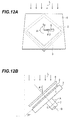
- the optical alignment-treatment can be conducted for a non-treated alignment film 2 using the method shown in Figs. 12A and 12B.
- the photo mask 6 is disposed such that the central line in the longitudinal direction of the light transmission section 5 almost orthogonally intersects the light L in a front view.
- the light L obliquely enters the non-treated alignment film 2 with an incident angle ⁇ 1.
- the other arrangement is substantially the same as for Figs. 2A and 2B.
- Figs. 12A and 12B are also included in Figs. 2A and 2B.
- Figs. 12A and 12B the same constituent components as those shown in Figs. 2A and 2B are assigned with the same reference numerals, and description thereof will be avoided.
- liquid-crystal molecules at the surface of the treated alignment film are concentrically aligned in a plane and liquid-crystal molecules at the surface of the non-treated alignment film are concentrically or radially aligned in a plane.
- the angle between the central line in the longitudinal direction of the light transmission section 5 and the light L in a front view can be appropriately selected in a range from 0° to 180° according to a material of the non-treated alignment film 2, the wavelength of the light L, a kind (polarized or non-polarized) of the light L, intensity of the light L, and the like.
- the light controlling device are a liquid-crystal lens, a liquid-crystal microlens, a liquid-crystal rotary wave plate, and liquid-crystal optical shutter.
- the light controlling device can be used as a single unit or in combination with various optical devices and/or various optical members, for example, with a linear polarizer, a circular polarizer, a cholesteric film, and the like.
- an iris can be assembled by combining a liquid-crystal lens with a polarizer.
- optical alignment-treatment are also applicable to the production of optical devices, for example, a liquid-crystal prism in which discontinuity existing in an alignment direction of liquid-crystal molecules does not cause any serious problem in practices. Moreover, these methods can be used to produce a liquid-crystal display.
- the liquid-crystal molecules can be uniformly aligned in any direction of azimuth in a plane at the surface of the liquid crystal and the alignment film.
- the light controlling device including liquid crystal facilitates a desired light control operation.
- the present invention is capable of aligning liquid-crystal molecules uniformly in any azimuth direction in a plane at a surface of an alignment film. This leads to a light controlling device to easily control light in a desired way.
Landscapes
- Physics & Mathematics (AREA)
- Nonlinear Science (AREA)
- Spectroscopy & Molecular Physics (AREA)
- Mathematical Physics (AREA)
- Chemical & Material Sciences (AREA)
- Crystallography & Structural Chemistry (AREA)
- General Physics & Mathematics (AREA)
- Optics & Photonics (AREA)
- Liquid Crystal (AREA)
Applications Claiming Priority (2)
| Application Number | Priority Date | Filing Date | Title |
|---|---|---|---|
| JP2000274344 | 2000-09-11 | ||
| JP2000274344A JP4748467B2 (ja) | 2000-09-11 | 2000-09-11 | 光制御素子とその製造方法、および光配向処理方法 |
Publications (2)
| Publication Number | Publication Date |
|---|---|
| EP1186940A2 true EP1186940A2 (fr) | 2002-03-13 |
| EP1186940A3 EP1186940A3 (fr) | 2003-05-28 |
Family
ID=18760115
Family Applications (1)
| Application Number | Title | Priority Date | Filing Date |
|---|---|---|---|
| EP01121604A Withdrawn EP1186940A3 (fr) | 2000-09-11 | 2001-09-11 | Dispositif pour le contrôle de la lumière utilisant un cristal liquide et son procédé de fabrication |
Country Status (3)
| Country | Link |
|---|---|
| US (1) | US20020033442A1 (fr) |
| EP (1) | EP1186940A3 (fr) |
| JP (1) | JP4748467B2 (fr) |
Cited By (8)
| Publication number | Priority date | Publication date | Assignee | Title |
|---|---|---|---|---|
| EP1353217A1 (fr) * | 2002-03-29 | 2003-10-15 | JSR Corporation | Procédé d'alignement optique et dispositif à cristaux liquides |
| EP1725908A4 (fr) * | 2004-01-22 | 2007-12-05 | Vescent Photonics Inc | Guide d'ondes a cristaux liquides possedant des formes refractives afin de controler dynamiquement la lumiere |
| US7570320B1 (en) | 2005-09-01 | 2009-08-04 | Vescent Photonics, Inc. | Thermo-optic liquid crystal waveguides |
| US8463080B1 (en) | 2004-01-22 | 2013-06-11 | Vescent Photonics, Inc. | Liquid crystal waveguide having two or more control voltages for controlling polarized light |
| US8860897B1 (en) | 2004-01-22 | 2014-10-14 | Vescent Photonics, Inc. | Liquid crystal waveguide having electric field orientated for controlling light |
| US8989523B2 (en) | 2004-01-22 | 2015-03-24 | Vescent Photonics, Inc. | Liquid crystal waveguide for dynamically controlling polarized light |
| US8995038B1 (en) | 2010-07-06 | 2015-03-31 | Vescent Photonics, Inc. | Optical time delay control device |
| US9366938B1 (en) | 2009-02-17 | 2016-06-14 | Vescent Photonics, Inc. | Electro-optic beam deflector device |
Families Citing this family (19)
| Publication number | Priority date | Publication date | Assignee | Title |
|---|---|---|---|---|
| JP3804934B2 (ja) * | 2002-03-29 | 2006-08-02 | Jsr株式会社 | 光配向法 |
| JP3844234B2 (ja) * | 2002-10-25 | 2006-11-08 | Jsr株式会社 | 光配向法および液晶表示素子 |
| KR101212135B1 (ko) * | 2005-06-14 | 2012-12-14 | 엘지디스플레이 주식회사 | 액정표시소자 및 그 제조방법 |
| WO2013031462A1 (fr) * | 2011-08-29 | 2013-03-07 | シャープ株式会社 | Procédé de fabrication d'un dispositif d'affichage à cristaux liquides |
| KR102243116B1 (ko) * | 2013-10-21 | 2021-04-22 | 메르크 파텐트 게엠베하 | 복굴절성 중합체 필름의 제조 방법 |
| WO2016026055A1 (fr) * | 2014-08-22 | 2016-02-25 | UNIVERSITé LAVAL | Dispositifs de modulateur à cristaux liquides basés sur des structures d'électrode non uniformes |
| US10552676B2 (en) | 2015-08-03 | 2020-02-04 | Facebook Technologies, Llc | Methods and devices for eye tracking based on depth sensing |
| US10459305B2 (en) | 2015-08-03 | 2019-10-29 | Facebook Technologies, Llc | Time-domain adjustment of phase retardation in a liquid crystal grating for a color display |
| US20170038591A1 (en) | 2015-08-03 | 2017-02-09 | Oculus Vr, Llc | Display with a Tunable Pinhole Array for Augmented Reality |
| US10338451B2 (en) | 2015-08-03 | 2019-07-02 | Facebook Technologies, Llc | Devices and methods for removing zeroth order leakage in beam steering devices |
| CN105093700B (zh) * | 2015-09-17 | 2019-01-22 | 京东方科技集团股份有限公司 | 一种取向装置、显示面板和显示装置 |
| US10247858B2 (en) | 2015-10-25 | 2019-04-02 | Facebook Technologies, Llc | Liquid crystal half-wave plate lens |
| US10416454B2 (en) | 2015-10-25 | 2019-09-17 | Facebook Technologies, Llc | Combination prism array for focusing light |
| US10203566B2 (en) | 2015-12-21 | 2019-02-12 | Facebook Technologies, Llc | Enhanced spatial resolution using a segmented electrode array |
| US11269220B2 (en) | 2016-06-14 | 2022-03-08 | Sharp Kabushiki Kaisha | Polarized-light irradiation device and method for manufacturing liquid crystal display device |
| WO2018180960A1 (fr) * | 2017-03-30 | 2018-10-04 | シャープ株式会社 | Procédé de fabrication d'une cellule à cristaux liquides et procédé de fabrication d'antenne de balayage |
| US11201411B2 (en) * | 2017-03-30 | 2021-12-14 | Sharp Kabushiki Kaisha | Liquid crystal cell and scanning antenna |
| US12007652B2 (en) * | 2018-06-15 | 2024-06-11 | Magic Leap, Inc. | Wide field-of-view polarization switches and methods of fabricating liquid crystal optical elements with pretilt |
| WO2019241575A1 (fr) | 2018-06-15 | 2019-12-19 | Magic Leap, Inc. | Commutateurs de polarisation à champ de vision large comprenant des éléments optiques à cristaux liquides à pré-inclinaison |
Family Cites Families (11)
| Publication number | Priority date | Publication date | Assignee | Title |
|---|---|---|---|---|
| JPH0830815B2 (ja) * | 1991-03-20 | 1996-03-27 | 株式会社ジーティシー | 液晶表示装置 |
| GB2255193B (en) * | 1991-04-24 | 1994-10-12 | Marconi Gec Ltd | Optical device |
| JPH04345124A (ja) * | 1991-05-23 | 1992-12-01 | Toyota Motor Corp | 焦点距離可変液晶レンズ |
| JPH06265902A (ja) * | 1993-03-11 | 1994-09-22 | Stanley Electric Co Ltd | 液晶表示装置及びその製造方法 |
| JPH06324337A (ja) * | 1993-03-15 | 1994-11-25 | Toshiba Corp | 液晶表示装置 |
| JP3127069B2 (ja) * | 1993-12-15 | 2001-01-22 | シャープ株式会社 | 液晶表示装置の製造方法 |
| JPH09243825A (ja) * | 1996-03-12 | 1997-09-19 | Fujitsu Ltd | 偏光板、その製造方法、及び、液晶表示装置 |
| JP3583250B2 (ja) * | 1997-01-27 | 2004-11-04 | アルプス電気株式会社 | 反射型液晶表示装置 |
| JPH11109303A (ja) * | 1997-09-30 | 1999-04-23 | Advantest Corp | 光結合器 |
| JP3540174B2 (ja) * | 1998-10-12 | 2004-07-07 | ウシオ電機株式会社 | 斜めから光を照射するプロキシミティ露光方法 |
| KR20000065706A (ko) * | 1999-04-08 | 2000-11-15 | 김순택 | 액정표시소자와 배향막의 표면 처리방법 및 장치 |
-
2000
- 2000-09-11 JP JP2000274344A patent/JP4748467B2/ja not_active Expired - Fee Related
-
2001
- 2001-09-10 US US09/950,142 patent/US20020033442A1/en not_active Abandoned
- 2001-09-11 EP EP01121604A patent/EP1186940A3/fr not_active Withdrawn
Cited By (15)
| Publication number | Priority date | Publication date | Assignee | Title |
|---|---|---|---|---|
| CN1450394B (zh) * | 2002-03-29 | 2010-04-28 | Jsr株式会社 | 光取向法及液晶显示元件 |
| EP1353217A1 (fr) * | 2002-03-29 | 2003-10-15 | JSR Corporation | Procédé d'alignement optique et dispositif à cristaux liquides |
| US7787085B2 (en) | 2002-03-29 | 2010-08-31 | Jsr Corporation | Optical alignment method and liquid crystal display element |
| US8380025B2 (en) | 2004-01-22 | 2013-02-19 | Vescent Photonics, Inc. | Liquid crystal waveguide having refractive shapes for dynamically controlling light |
| US8311372B2 (en) | 2004-01-22 | 2012-11-13 | Vescent Photonics, Inc. | Liquid crystal waveguide having refractive shapes for dynamically controlling light |
| EP1725908A4 (fr) * | 2004-01-22 | 2007-12-05 | Vescent Photonics Inc | Guide d'ondes a cristaux liquides possedant des formes refractives afin de controler dynamiquement la lumiere |
| US8463080B1 (en) | 2004-01-22 | 2013-06-11 | Vescent Photonics, Inc. | Liquid crystal waveguide having two or more control voltages for controlling polarized light |
| US8860897B1 (en) | 2004-01-22 | 2014-10-14 | Vescent Photonics, Inc. | Liquid crystal waveguide having electric field orientated for controlling light |
| US8989523B2 (en) | 2004-01-22 | 2015-03-24 | Vescent Photonics, Inc. | Liquid crystal waveguide for dynamically controlling polarized light |
| US7570320B1 (en) | 2005-09-01 | 2009-08-04 | Vescent Photonics, Inc. | Thermo-optic liquid crystal waveguides |
| US9366938B1 (en) | 2009-02-17 | 2016-06-14 | Vescent Photonics, Inc. | Electro-optic beam deflector device |
| US9829766B2 (en) | 2009-02-17 | 2017-11-28 | Analog Devices, Inc. | Electro-optic beam deflector device |
| US9880443B2 (en) | 2009-02-17 | 2018-01-30 | Analog Devices, Inc. | Electro-optic beam deflector device having adjustable in-plane beam control |
| US9885892B2 (en) | 2009-02-17 | 2018-02-06 | Analog Devices, Inc. | Electro-optic beam deflector device |
| US8995038B1 (en) | 2010-07-06 | 2015-03-31 | Vescent Photonics, Inc. | Optical time delay control device |
Also Published As
| Publication number | Publication date |
|---|---|
| JP2002082333A (ja) | 2002-03-22 |
| JP4748467B2 (ja) | 2011-08-17 |
| EP1186940A3 (fr) | 2003-05-28 |
| US20020033442A1 (en) | 2002-03-21 |
Similar Documents
| Publication | Publication Date | Title |
|---|---|---|
| EP1186940A2 (fr) | Dispositif pour le contrôle de la lumière utilisant un cristal liquide et son procédé de fabrication | |
| TW567378B (en) | Liquid-crystal display device and method of fabricating the same | |
| US20230418109A1 (en) | Liquid crystal display apparatus | |
| US20020080320A1 (en) | Liquid crystal display device | |
| US20090002612A1 (en) | Liquid Crystal Display Panel and Fabrication Method For Liquid Crystal Display Panel | |
| JPH06324337A (ja) | 液晶表示装置 | |
| US6475705B2 (en) | Method for manufacturing a multidomain liquid crystal display panel | |
| KR20020002248A (ko) | 액정표시소자 및 그 제조방법 | |
| US8830427B2 (en) | Liquid crystal display | |
| JP2002532753A (ja) | マルチツイストカラー液晶ディスプレイ | |
| US7365817B2 (en) | Multi-domain liquid crystal display and method for manufacturing the same | |
| CN101206329A (zh) | 制造液晶显示器的方法 | |
| US9891466B2 (en) | Liquid crystal display panel and fabrication method thereof | |
| KR101040457B1 (ko) | 코팅형 보상필름을 적용한 액정표시장치 및 그 제조방법 | |
| US20080291377A1 (en) | Liquid Crystal Display Device and Manufacturing Method Thereof | |
| KR100767587B1 (ko) | 코팅형 보상필름을 적용한 액정표시장치 및 그 제조방법 | |
| KR101146985B1 (ko) | 표시 장치 및 이의 제조 방법 | |
| JP2739041B2 (ja) | 液晶表示装置の製造方法及び液晶表示装置 | |
| KR100431052B1 (ko) | 표면 굴곡에 의하여 형성된 다중 영역 효과를 가지는 액정표시 장치 | |
| KR101438040B1 (ko) | 프린지 필드 스위칭 액정표시장치 및 그 제조방법 | |
| KR100961265B1 (ko) | 광학 보상 필름 및 이를 이용한 액정표시장치 | |
| JPH10133206A (ja) | 液晶表示装置およびその製造方法 | |
| WO2012063936A1 (fr) | Dispositif d'affichage à cristaux liquides et procédé de fabrication d'un dispositif d'affichage à cristaux liquides | |
| KR20050078468A (ko) | 액정 표시 장치와 이의 제조 방법 | |
| KR20110078897A (ko) | 낮은 수직 선경사각을 갖는 액정표시장치 및 그 제조 방법 |
Legal Events
| Date | Code | Title | Description |
|---|---|---|---|
| PUAI | Public reference made under article 153(3) epc to a published international application that has entered the european phase |
Free format text: ORIGINAL CODE: 0009012 |
|
| AK | Designated contracting states |
Kind code of ref document: A2 Designated state(s): AT BE CH CY DE DK ES FI FR GB GR IE IT LI LU MC NL PT SE TR |
|
| AX | Request for extension of the european patent |
Free format text: AL;LT;LV;MK;RO;SI |
|
| PUAL | Search report despatched |
Free format text: ORIGINAL CODE: 0009013 |
|
| AK | Designated contracting states |
Designated state(s): AT BE CH CY DE DK ES FI FR GB GR IE IT LI LU MC NL PT SE TR |
|
| AX | Request for extension of the european patent |
Extension state: AL LT LV MK RO SI |
|
| 17P | Request for examination filed |
Effective date: 20031128 |
|
| AKX | Designation fees paid |
Designated state(s): DE FR GB |
|
| 17Q | First examination report despatched |
Effective date: 20040116 |
|
| STAA | Information on the status of an ep patent application or granted ep patent |
Free format text: STATUS: THE APPLICATION IS DEEMED TO BE WITHDRAWN |
|
| 18D | Application deemed to be withdrawn |
Effective date: 20040727 |