EP1189059A1 - Détecteur de cellules sanguines, analyseur de sang et méthode utilisant le détecteur - Google Patents
Détecteur de cellules sanguines, analyseur de sang et méthode utilisant le détecteur Download PDFInfo
- Publication number
- EP1189059A1 EP1189059A1 EP01121733A EP01121733A EP1189059A1 EP 1189059 A1 EP1189059 A1 EP 1189059A1 EP 01121733 A EP01121733 A EP 01121733A EP 01121733 A EP01121733 A EP 01121733A EP 1189059 A1 EP1189059 A1 EP 1189059A1
- Authority
- EP
- European Patent Office
- Prior art keywords
- blood
- specimen
- blood cell
- orifice
- supplying
- Prior art date
- Legal status (The legal status is an assumption and is not a legal conclusion. Google has not performed a legal analysis and makes no representation as to the accuracy of the status listed.)
- Granted
Links
- 210000004369 blood Anatomy 0.000 title claims abstract description 109
- 239000008280 blood Substances 0.000 title claims abstract description 109
- 210000000601 blood cell Anatomy 0.000 title claims abstract description 33
- 238000000034 method Methods 0.000 title claims description 14
- 239000003085 diluting agent Substances 0.000 claims description 113
- 210000003743 erythrocyte Anatomy 0.000 claims description 85
- 210000000265 leukocyte Anatomy 0.000 claims description 84
- 239000007788 liquid Substances 0.000 claims description 84
- 238000004458 analytical method Methods 0.000 claims description 48
- 102000001554 Hemoglobins Human genes 0.000 claims description 22
- 108010054147 Hemoglobins Proteins 0.000 claims description 22
- 238000004140 cleaning Methods 0.000 claims description 19
- 230000000717 retained effect Effects 0.000 claims description 5
- 230000001678 irradiating effect Effects 0.000 claims 3
- 238000007599 discharging Methods 0.000 claims 1
- 239000003795 chemical substances by application Substances 0.000 description 21
- 238000010790 dilution Methods 0.000 description 20
- 239000012895 dilution Substances 0.000 description 20
- 210000002445 nipple Anatomy 0.000 description 13
- 239000002245 particle Substances 0.000 description 12
- 238000005070 sampling Methods 0.000 description 11
- 210000001772 blood platelet Anatomy 0.000 description 9
- 238000002347 injection Methods 0.000 description 9
- 239000007924 injection Substances 0.000 description 9
- 238000009826 distribution Methods 0.000 description 7
- 238000002835 absorbance Methods 0.000 description 6
- 238000002360 preparation method Methods 0.000 description 6
- 238000004159 blood analysis Methods 0.000 description 5
- 238000004891 communication Methods 0.000 description 4
- 238000001514 detection method Methods 0.000 description 4
- 238000010586 diagram Methods 0.000 description 4
- 238000005534 hematocrit Methods 0.000 description 4
- 239000000463 material Substances 0.000 description 3
- 238000005259 measurement Methods 0.000 description 3
- 239000013043 chemical agent Substances 0.000 description 2
- 238000010276 construction Methods 0.000 description 2
- 239000012530 fluid Substances 0.000 description 2
- BASFCYQUMIYNBI-UHFFFAOYSA-N platinum Chemical compound [Pt] BASFCYQUMIYNBI-UHFFFAOYSA-N 0.000 description 2
- 229920002492 poly(sulfone) Polymers 0.000 description 2
- 239000011347 resin Substances 0.000 description 2
- 229920005989 resin Polymers 0.000 description 2
- 238000007865 diluting Methods 0.000 description 1
- 239000011521 glass Substances 0.000 description 1
- 239000000203 mixture Substances 0.000 description 1
- 230000002093 peripheral effect Effects 0.000 description 1
- 229910052697 platinum Inorganic materials 0.000 description 1
- 239000010979 ruby Substances 0.000 description 1
- 229910001750 ruby Inorganic materials 0.000 description 1
- 238000005549 size reduction Methods 0.000 description 1
Images


Classifications
-
- G—PHYSICS
- G01—MEASURING; TESTING
- G01N—INVESTIGATING OR ANALYSING MATERIALS BY DETERMINING THEIR CHEMICAL OR PHYSICAL PROPERTIES
- G01N15/00—Investigating characteristics of particles; Investigating permeability, pore-volume or surface-area of porous materials
- G01N15/10—Investigating individual particles
- G01N15/14—Optical investigation techniques, e.g. flow cytometry
-
- G—PHYSICS
- G01—MEASURING; TESTING
- G01N—INVESTIGATING OR ANALYSING MATERIALS BY DETERMINING THEIR CHEMICAL OR PHYSICAL PROPERTIES
- G01N15/00—Investigating characteristics of particles; Investigating permeability, pore-volume or surface-area of porous materials
- G01N15/10—Investigating individual particles
- G01N15/1031—Investigating individual particles by measuring electrical or magnetic effects
- G01N15/12—Investigating individual particles by measuring electrical or magnetic effects by observing changes in resistance or impedance across apertures when traversed by individual particles, e.g. by using the Coulter principle
- G01N15/134—Devices using two or more apertures
-
- G—PHYSICS
- G01—MEASURING; TESTING
- G01N—INVESTIGATING OR ANALYSING MATERIALS BY DETERMINING THEIR CHEMICAL OR PHYSICAL PROPERTIES
- G01N15/00—Investigating characteristics of particles; Investigating permeability, pore-volume or surface-area of porous materials
- G01N15/10—Investigating individual particles
- G01N15/1031—Investigating individual particles by measuring electrical or magnetic effects
- G01N15/12—Investigating individual particles by measuring electrical or magnetic effects by observing changes in resistance or impedance across apertures when traversed by individual particles, e.g. by using the Coulter principle
- G01N15/131—Details
- G01N2015/133—Flow forming
-
- Y—GENERAL TAGGING OF NEW TECHNOLOGICAL DEVELOPMENTS; GENERAL TAGGING OF CROSS-SECTIONAL TECHNOLOGIES SPANNING OVER SEVERAL SECTIONS OF THE IPC; TECHNICAL SUBJECTS COVERED BY FORMER USPC CROSS-REFERENCE ART COLLECTIONS [XRACs] AND DIGESTS
- Y10—TECHNICAL SUBJECTS COVERED BY FORMER USPC
- Y10T—TECHNICAL SUBJECTS COVERED BY FORMER US CLASSIFICATION
- Y10T436/00—Chemistry: analytical and immunological testing
- Y10T436/10—Composition for standardization, calibration, simulation, stabilization, preparation or preservation; processes of use in preparation for chemical testing
- Y10T436/101666—Particle count or volume standard or control [e.g., platelet count standards, etc.]
-
- Y—GENERAL TAGGING OF NEW TECHNOLOGICAL DEVELOPMENTS; GENERAL TAGGING OF CROSS-SECTIONAL TECHNOLOGIES SPANNING OVER SEVERAL SECTIONS OF THE IPC; TECHNICAL SUBJECTS COVERED BY FORMER USPC CROSS-REFERENCE ART COLLECTIONS [XRACs] AND DIGESTS
- Y10—TECHNICAL SUBJECTS COVERED BY FORMER USPC
- Y10T—TECHNICAL SUBJECTS COVERED BY FORMER US CLASSIFICATION
- Y10T436/00—Chemistry: analytical and immunological testing
- Y10T436/11—Automated chemical analysis
- Y10T436/117497—Automated chemical analysis with a continuously flowing sample or carrier stream
-
- Y—GENERAL TAGGING OF NEW TECHNOLOGICAL DEVELOPMENTS; GENERAL TAGGING OF CROSS-SECTIONAL TECHNOLOGIES SPANNING OVER SEVERAL SECTIONS OF THE IPC; TECHNICAL SUBJECTS COVERED BY FORMER USPC CROSS-REFERENCE ART COLLECTIONS [XRACs] AND DIGESTS
- Y10—TECHNICAL SUBJECTS COVERED BY FORMER USPC
- Y10T—TECHNICAL SUBJECTS COVERED BY FORMER US CLASSIFICATION
- Y10T436/00—Chemistry: analytical and immunological testing
- Y10T436/11—Automated chemical analysis
- Y10T436/119163—Automated chemical analysis with aspirator of claimed structure
Definitions
- the present invention relates to a detector for blood analysis and to a blood analyzer and a blood analyzing method. More particularly, the invention relates to a detector for analyzing white blood cells and red blood cells in a blood sample by an electric resistance method and to a blood analyzer for determination of the numbers and particle size distributions of the white blood cells and the red blood cells.
- the flow circuit includes a plurality of fluid devices such as values and pumps which make a network using tubes and nipples.
- the orifices 20, 21 are each generally formed in a disk of artificial ruby, because they are required to be highly resistant to breakage and chemical agents and to have a high dimensional accuracy.
- platinum is employed which is highly resistant to chemical agents.
- the materials for the orifices and the electrodes are very expensive, increasing the costs of the conventional blood analyzer in which these components are provided in the white blood cell detector and the red blood cell detector. Since the white blood cell detector and the red blood cell detector are separately provided, the diluent pumps for supplying the diluent and the valves for switching the flow paths should be provided for each of the white blood cell detector and the red blood cell detector. This increases the complexity, size and costs of the analyzer.
- the present invention is directed to a detector which can singly achieve easy and accurate analysis of white blood cells and red blood cells.
- the present invention is further directed to simplification, size reduction and cost reduction of a blood analyzer.
- a blood cell detector which comprises an orifice section having a single orifice, a first supplying section for supplying a first blood specimen into the orifice section, a second supplying section for supplying a second blood specimen into the orifice section, and first and second electrodes provided on opposite sides of the orifice for detecting a change in impedance of each of the first and second blood specimens when the first and second blood specimens are selectively caused to pass through the orifice.
- the blood cell detector comprises an orifice section having a single orifice, a first supplying section for supplying a first blood specimen into the orifice section, a second supplying section for supplying a second blood specimen into the orifice section, and first and second electrodes provided on opposite sides of the orifice for detecting a change in impedance of each of the first and second blood specimens when the first and second blood specimens are selectively caused to pass through the orifice.
- the first and second blood specimens may be caused to pass through the orifice in the same direction or in opposite directions.
- the first blood specimen may be a specimen for analysis of white blood cells
- the second blood specimen may be a specimen for analysis of red blood cells.
- the first supplying section may include a container pervious to light for retaining a specimen for analysis of hemoglobin, a light source for applying light to the container, and a light receiving section for receiving light transmitted through the container.
- the second supplying section may include sheath flow means for causing the red blood cell specimen to be enclosed in a sheath liquid to pass through the orifice.
- the sheath flow means may include a nozzle for ejecting the red blood cell specimen into the orifice, and a sheath liquid supplying section for supplying the sheath liquid in which the red blood cell specimen is enclosed to pass through the orifice.
- the first and second supplying sections may include first and second blood specimen containers, respectively.
- the first supplying section may include a blood specimen container for retaining the first blood specimen
- the second supplying section may include a nozzle for ejecting the second blood specimen into the orifice, and a sheath liquid supplying section for supplying a sheath liquid in which the ejected second blood specimen is enclosed to pass through the orifice.
- a blood analyzer having the aforesaid blood cell detector.
- an electric resistance method is employed for detection of blood cells.
- the electric resistance method has such drawbacks that there are variations in detection signal depending on a position in the orifice through which each particle passes, that a plurality of particles passing through the orifice in a close positional relation are counted as a single particle, and that particles having passed through the orifice are liable to stay in the vicinity of the orifice to cause noises.
- a sheath flow method is advantageously employed.
- the sheath flow method herein means a method such that a specimen is fed into the orifice while being enclosed in a sheath liquid.
- a nozzle is preferably provided for allowing the red blood cell specimen to be enclosed in the sheath liquid to be fed into the orifice. This drastically improves the accuracy of the analysis of the red blood cells and platelets. Further, a measuring factor for the red blood cell specimen can be reduced, thereby allowing for reduction in the consumption of a diluent and drastic reduction in the period required for the analysis.
- Basic blood analysis items include the number of white blood cells (WBC), the number of red blood cells (RBC), the number of platelets (PLT), the amount of hemoglobin (HGB), and hematocrit (HCT).
- the hematocrit is determined by processing red blood cell detection signals.
- the inventive blood cell detector preferably further includes a hemoglobin specimen container for retaining a hemoglobin specimen for determination of the hemoglobin amount. With this arrangement, the blood analyzer having the inventive blood cell detector is capable of determining all the basic blood analysis items.
- the red blood cells and the platelets are present in concentrations of about 4,000,000/ ⁇ l and about 200,000/ ⁇ l, respectively, in a normal blood sample and, hence, differ in concentration by an order of magnitude. Further, the red blood cells and the platelets differ in size and, therefore, can simultaneously be analyzed by employing the same blood specimen.
- the white blood cells are present in a concentration of about 5,000/ ⁇ l in a normal blood sample and, hence, are smaller in concentration by three orders of magnitude than the red blood cells, but similar in size to the red blood cells. Therefore, it is impossible to simultaneously analyze the red blood cells and the white blood cells by employing the same blood specimen.
- a hemolyzed blood sample is employed for the analysis of the white blood cells.
- An hemolyzation agent for hemolyzation for the white blood cell analysis may also be employed for hemolyzation for the hemoglobin analysis, depending on its composition.
- the blood cells are preferably allowed to pass through the orifice at predetermined intervals for higher accuracy. Therefore, the white blood cells and the red blood cells which are different in concentration are separately analyzed by diluting a blood sample by different dilution factors. Since the platelets and the red blood cells in blood are two to three orders of magnitude greater in concentration than the white blood cells, the dilution factor for the red blood cell specimen should correspondingly be increased as compared with the dilution factor for the white blood cell specimen. Therefore, it is a conventional practice to dilute the blood sample, for example, 25,000 times for the red blood cell specimen and 500 times for the white blood cell specimen and supply the red blood cell specimen and the white blood cell specimen to the corresponding detectors. Where the sheath flow method is employed, on the other hand, the dilution factor for the red blood cell specimen can be reduced to about 750, while the dilution factor for the white blood cell specimen is 500.
- the blood sample to be analyzed is diluted by different dilution factors for the red blood cell specimen and for the white blood cell specimen.
- the blood sample is diluted with a diluent by a high dilution factor, e.g., by a factor of 25,000, at one time, the ratio of the amount of the blood sample to the amount of the diluent is so small that an error in the amount of the blood sample significantly influences the analysis. Therefore, it is preferred to prepare the red blood cell specimen through two-stage dilution, and to prepare the white blood cell specimen through one-stage dilution.
- Fig. 2 is a sectional view illustrating a white blood cell and red blood cell detector to be employed in Embodiment 1
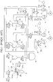
- Fig. 3 shows a flow circuit of a blood analyzer according to Embodiment 1.
- the flow circuit includes a plurality of fluid devices which make a network using tubes and nipples.
- the white blood cell and red blood cell detector 50 includes a first liquid container 31, a second liquid container 36, a third liquid container 42, a disk 30 having an orifice 33, a jet nozzle 32, and electrodes 34, 35 (a negative electrode 34 and a positive electrode 35) for detecting a change in impedance.
- the orifice 33 has a diameter that allows for passage of a white blood cell and a red blood cell. Changes in impedance detected by the electrodes 34, 35 when a blood cell passes through the center of the orifice 33 and when the blood cell passes through a portion of the orifice other than the center thereof differ from each other. This reduces the accuracy of the analysis.
- the diameter of the orifice 33 is herein set to 50 ⁇ m-100 ⁇ m. Preferably, the diameter is 80 ⁇ m.
- the first liquid container 31 and the third liquid container 42 are combined together, and the third liquid container 42 is a rectangular column of a transparent polysulfone resin pervious to light.
- the material for the third liquid container is not limited to the polysulfone resin, but may be glass.
- the shape of the third liquid container is not limited to a rectangular shape, but may be a cylindrical shape or a combination of a rectangular shape and a cylindrical shape.
- a diluent and a hemolyzation agent are respectively pumped into the first liquid container 31 via a diluent injection nozzle 80 and a hemolyzation agent injection nozzle 81 by a diluent pump 51 and a hemolyzation agent pump 53 shown in Fig. 3.
- the second liquid container 36 is provided with nipples 82, 32 for connection to an external flow circuit. Liquid within the first liquid container 31 and the third liquid container 42 is discharged from a drain nipple 84.
- a mixing chamber 55 shown in Fig. 3 and the first liquid container 31 each have an open top, through which a blood sample and the like are injected from a pipette 61.
- the diluent pump 51, a quantitative sampling pump 52 and the hemolyzation agent pump 53 shown in Fig. 3 are driven by stepping motors 58, 59.
- reference characters V14 to V18, V20 to V24, V30, V33, V35 to V38 denote electromagnetic valves. It is herein assumed that these valves are normally closed.
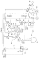
- Fig. 8 is an electric circuit diagram of the blood analyzer according to Embodiment 1.
- a signal processing section 200 receives a signal from an input section 201 for presetting various processing conditions of the signal processing section 200 and outputs driving signals to the electromagnetic values V14-V18, V20-V24, V30, V33 and V35-V38, the stepping motors 58, 59 and a manipulator 203 for manipulating the pipette 61.
- the signal processing section 200 also drives a lamp 66 and receives signals from a light receiving section 67 (see, Fig. 3) and the electrodes 34, 35.
- the signal processing section 200 processes the signal from the electrodes 34, 35 for determination of WBC, RBC, PLT and HCT and also processes the signal from the light receiving section 67 for determination of the hemoglobin amount (HGB).
- a result of the determination is output from an output section 202.
- the signal processing section 200 includes a microcomputer having a CPU, a ROM and a RAM and driving circuits for driving the electromagnetic values V14-V18, V20-V24, V30, V33, and V35-V38, the stepping motors 58, 59, the manipulator 203 and the lump 66.
- the lump 66 is a light emitting diode and the light receiving section includes a photo diode.
- the manipulator 203 includes stepping motors for moving the pipette 61 vertically and horizontally.
- the analysis of white blood cells is carried out in the following sequence.
- red blood cells The analysis of red blood cells is carried out in the following sequence.
- the cleaning of the detector for the next blood analysis is carried out in the following sequence.
- the absorbance of a hemolyzed blood sample is measured.
- STROMATOLYSER(TM) WH available from Sysmex
- the hemolyzation can effectively be carried out for the white blood cell analysis and for the hemoglobin analysis.
- the absorbance is first measured with the diluent retained in the third liquid container 42 for blank measurement, and then is measured with a hemoglobin specimen retained in the third liquid container 42 by the lamp 66 and the light receiving section 67.
- the hemoglobin amount is determined by calculating a difference between the measurements of the absorbance.
- hemoglobin The analysis of the hemoglobin is carried out in the following sequence.
- a timing chart is shown in Fig. 7 which illustrates operations to be performed in the respective components over time (in the order from the left side to the right side). Hatched portions in the timing chart indicate operating periods.
- a detector according to this embodiment is adapted to perform the analysis by causing the white blood cell specimen and the red blood cell specimen to pass through the orifice by suction.
- An explanation will be given to Embodiment 2 with reference to Figs. 4 to 6.
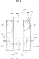
- Fig. 4 is a front view illustrating a white blood cell and red blood cell detector 50a according to Embodiment 2.
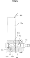
- Fig. 5 is a sectional view as seen in the direction of arrows A-A in Fig. 4
- Fig. 6 is a sectional view as seen in the direction of arrows B-B in Fig. 4.
- the white blood cell and red blood cell detector 50a includes a first liquid container 31a for retaining a white blood cell specimen, a second liquid container 36a for retaining a red blood cell specimen, a disk 30a having an orifice 33a, electrodes 34a, 35a (a negative electrode 34a and a positive electrode 35a) for detecting a change in impedance, and an electrode chamber 120 in which the electrode 34a is disposed.
- the white blood cell specimen is supplied from the first liquid container 31a through a flow path 114 and the electrode chamber 120, and caused to pass through the orifice 33a.
- the red blood cell specimen is supplied from the second liquid container 36a through a flow path 115 and the electrode chamber 120, and caused to pass through the orifice 33a.
- the orifice 33a has a diameter of 80 ⁇ m as in Embodiment 1.
- the first and second liquid containers 31a, 36a respectively have open tops, through which a diluent and a hemolyzation agent are injected therein from diluent injection nozzles 80a, 80b and a hemolyzation agent injection nozzle 81a. Further, a blood sample is injected from a pipette (not shown) through the open tops of the first and second liquid containers 31a, 36a.
- the detector 50a further has nipples 84a, 116, 118, 119 for connection to an external flow circuit.
- a valve V100 is switched to prevent or permit passage of the white blood cell specimen from a discharge path 111 of the first liquid container 31a to the flow path 114.
- a valve V101 is switched to prevent or permit passage of the red blood cell specimen from a discharge path 112 of the second liquid container 36a to the flow path 115.
- the valves V100, V101 are switched to open or close the flow paths 114 and 115, respectively, by moving movable pieces P therein in the direction of an arrow C.
- the white blood cell and red blood cell detector 50a has a hemoglobin specimen retaining section provided in the first liquid container 31a thereof, a lamp and a light receiving section, the hemoglobin analysis can be performed.
- the detector is adapted to intermittently inject air for a predetermined period into the specimens in the first and second liquid containers 31a, 36a through the nipples 118, 119, the specimens can be agitated.
- variations in the concentrations of the specimens in the containers can be eliminated for improvement of the accuracy of the analysis.
- white blood cells and red blood cells in a blood sample can easily and accurately be analyzed with the use of a single detector. Since the number of diluent pumps, the number of valves and the number of electrodes can be reduced, a less expensive blood analyzer can be provided which has a simplified construction and a reduced size.
Landscapes
- Chemical & Material Sciences (AREA)
- Dispersion Chemistry (AREA)
- Physics & Mathematics (AREA)
- Health & Medical Sciences (AREA)
- Life Sciences & Earth Sciences (AREA)
- Analytical Chemistry (AREA)
- Biochemistry (AREA)
- General Health & Medical Sciences (AREA)
- General Physics & Mathematics (AREA)
- Immunology (AREA)
- Pathology (AREA)
- Investigating Or Analysing Biological Materials (AREA)
- Investigating Or Analyzing Materials By The Use Of Electric Means (AREA)
Applications Claiming Priority (2)
| Application Number | Priority Date | Filing Date | Title |
|---|---|---|---|
| JP2000282458 | 2000-09-18 | ||
| JP2000282458 | 2000-09-18 |
Publications (2)
| Publication Number | Publication Date |
|---|---|
| EP1189059A1 true EP1189059A1 (fr) | 2002-03-20 |
| EP1189059B1 EP1189059B1 (fr) | 2009-06-24 |
Family
ID=18766974
Family Applications (1)
| Application Number | Title | Priority Date | Filing Date |
|---|---|---|---|
| EP01121733A Expired - Lifetime EP1189059B1 (fr) | 2000-09-18 | 2001-09-18 | Détecteur de cellules sanguines, analyseur de sang et méthode utilisant le détecteur |
Country Status (4)
| Country | Link |
|---|---|
| US (1) | US6716633B2 (fr) |
| EP (1) | EP1189059B1 (fr) |
| AT (1) | ATE434760T1 (fr) |
| DE (1) | DE60139056D1 (fr) |
Cited By (5)
| Publication number | Priority date | Publication date | Assignee | Title |
|---|---|---|---|---|
| FR2841653A1 (fr) * | 2002-06-26 | 2004-01-02 | Abx Sa | Procede et dispositif d'analyse d'un echantillon de sang |
| EP1378750A1 (fr) * | 2002-07-01 | 2004-01-07 | Sysmex Corporation | Analyseurs de sang et méthodes d'analyse de sang |
| KR100552620B1 (ko) * | 2004-01-13 | 2006-02-20 | 플래닛팔이 주식회사 | 적혈구 지수 측정 장치 및 방법 |
| CN103389386A (zh) * | 2012-05-09 | 2013-11-13 | 深圳中科强华科技有限公司 | 便携型三分类血细胞分析仪液路系统及其方法 |
| WO2021147179A1 (fr) * | 2020-01-22 | 2021-07-29 | 深圳市锦瑞生物科技有限公司 | Procédé de détection de particules de sang et analyseur de sang associé |
Families Citing this family (8)
| Publication number | Priority date | Publication date | Assignee | Title |
|---|---|---|---|---|
| US7487061B2 (en) | 2002-05-23 | 2009-02-03 | Sysmex Corporation | Sample analyzer |
| JP4926812B2 (ja) * | 2007-02-01 | 2012-05-09 | シスメックス株式会社 | 血球分析装置および体液分析方法 |
| JP5162177B2 (ja) * | 2007-07-31 | 2013-03-13 | シスメックス株式会社 | 粒子分析装置及び粒子分析方法 |
| EP2071339A3 (fr) | 2007-12-12 | 2015-05-20 | Sysmex Corporation | Système pour fournir des informations de test animal et procédé pour fournir des informations de test animal |
| CN104713816B (zh) * | 2015-02-04 | 2017-06-23 | 深圳市帝迈生物技术有限公司 | 一种全血crp检测装置与方法、及一种血液细胞分析仪 |
| CN111712703B (zh) * | 2019-11-18 | 2024-04-12 | 深圳迈瑞生物医疗电子股份有限公司 | 样本分析仪及样本分析方法 |
| CN113702267B (zh) * | 2020-05-22 | 2025-08-12 | 深圳迈瑞动物医疗科技股份有限公司 | 血红蛋白浓度的检测方法及血液细胞分析仪 |
| CN114859068B (zh) * | 2021-02-03 | 2025-09-23 | 深圳市帝迈生物技术有限公司 | 试剂盒及poct血细胞分析仪 |
Citations (4)
| Publication number | Priority date | Publication date | Assignee | Title |
|---|---|---|---|---|
| US4078211A (en) * | 1976-09-29 | 1978-03-07 | Coulter Electronics, Inc. | Method and apparatus for balancing particle detecting signals generated in a particle study device having multiple apertures |
| EP0652428A1 (fr) * | 1993-11-04 | 1995-05-10 | Toa Medical Electronics Co., Ltd. | Analyseur de particules |
| WO2000049385A2 (fr) * | 1999-02-16 | 2000-08-24 | Coulter International Corp. | Procede et appareil d'analyse des globules dans un echantillon de sang entier |
| EP1069423A2 (fr) * | 1999-07-16 | 2001-01-17 | Sysmex Corporation | Cuve de circulation pour un appareil d'analyse de particules avec une région de détection électrique |
Family Cites Families (13)
| Publication number | Priority date | Publication date | Assignee | Title |
|---|---|---|---|---|
| US3921066A (en) * | 1974-02-25 | 1975-11-18 | Angel Eng Corp | Blood test device and method |
| US4729876A (en) * | 1984-11-27 | 1988-03-08 | Nova Celltrak, Inc. | Blood analysis system |
| WO1989004961A1 (fr) * | 1987-11-13 | 1989-06-01 | Techne Corporation | Appareil hematologique de comptage de cellules |
| FR2629206B1 (fr) * | 1988-03-28 | 1991-01-04 | Melet Francois | Analyseur hematologique automatique simplifie |
| FR2629207B1 (fr) * | 1988-07-07 | 1991-05-31 | Melet Francois | Analyseur hematologique automatique a dispositif simplifie de prelevement et de distribution |
| ATE130679T1 (de) * | 1988-07-07 | 1995-12-15 | Francois Melet | Vereinfachter lysekreislauf für einen automatischen blutanalysator. |
| JP2815435B2 (ja) * | 1989-12-22 | 1998-10-27 | 株式会社日立製作所 | 粒子解析装置及び血球カウンタ |
| JP2965688B2 (ja) * | 1990-11-30 | 1999-10-18 | シスメックス株式会社 | 粒子検出装置 |
| JPH07119757B2 (ja) * | 1991-03-31 | 1995-12-20 | 日本光電工業株式会社 | 血球計数装置 |
| US5380491A (en) * | 1993-01-21 | 1995-01-10 | Cdc Technologies, Inc. | Apparatus for pumping and directing fluids for hematology testing |
| SE513881C2 (sv) * | 1994-01-10 | 2000-11-20 | Boule Medical Ab | Förfarande och anordning för analys av vätskeprover |
| FR2771175B1 (fr) * | 1997-11-19 | 2000-02-18 | Francois Melet | Dispositif automatique compteur analyseur d'hematologie |
| GB9810493D0 (en) * | 1998-05-16 | 1998-07-15 | Microbial Systems Ltd | Particle detector system |
-
2001
- 2001-09-18 EP EP01121733A patent/EP1189059B1/fr not_active Expired - Lifetime
- 2001-09-18 AT AT01121733T patent/ATE434760T1/de not_active IP Right Cessation
- 2001-09-18 DE DE60139056T patent/DE60139056D1/de not_active Expired - Lifetime
- 2001-09-18 US US09/954,057 patent/US6716633B2/en not_active Expired - Fee Related
Patent Citations (4)
| Publication number | Priority date | Publication date | Assignee | Title |
|---|---|---|---|---|
| US4078211A (en) * | 1976-09-29 | 1978-03-07 | Coulter Electronics, Inc. | Method and apparatus for balancing particle detecting signals generated in a particle study device having multiple apertures |
| EP0652428A1 (fr) * | 1993-11-04 | 1995-05-10 | Toa Medical Electronics Co., Ltd. | Analyseur de particules |
| WO2000049385A2 (fr) * | 1999-02-16 | 2000-08-24 | Coulter International Corp. | Procede et appareil d'analyse des globules dans un echantillon de sang entier |
| EP1069423A2 (fr) * | 1999-07-16 | 2001-01-17 | Sysmex Corporation | Cuve de circulation pour un appareil d'analyse de particules avec une région de détection électrique |
Non-Patent Citations (1)
| Title |
|---|
| TATSUMI NORIYUKI ET AL.: "Principle of Blood cell Counter - Development of Electric Inpedance Method", SYSMEX JOURNAL INTERNATIONAL, vol. 9, no. 1, 1999, pages 8 - 20, XP002185485 * |
Cited By (8)
| Publication number | Priority date | Publication date | Assignee | Title |
|---|---|---|---|---|
| FR2841653A1 (fr) * | 2002-06-26 | 2004-01-02 | Abx Sa | Procede et dispositif d'analyse d'un echantillon de sang |
| WO2004003517A1 (fr) * | 2002-06-26 | 2004-01-08 | Abx | Procede et dispositif d'analyse d'un echantillon de sang |
| EP1378750A1 (fr) * | 2002-07-01 | 2004-01-07 | Sysmex Corporation | Analyseurs de sang et méthodes d'analyse de sang |
| US7906073B2 (en) | 2002-07-01 | 2011-03-15 | Sysmex Corporation | Analyzers and methods for analyzing analytes |
| KR100552620B1 (ko) * | 2004-01-13 | 2006-02-20 | 플래닛팔이 주식회사 | 적혈구 지수 측정 장치 및 방법 |
| CN103389386A (zh) * | 2012-05-09 | 2013-11-13 | 深圳中科强华科技有限公司 | 便携型三分类血细胞分析仪液路系统及其方法 |
| CN103389386B (zh) * | 2012-05-09 | 2014-09-24 | 深圳中科强华科技有限公司 | 便携型三分类血细胞分析仪液路系统及其方法 |
| WO2021147179A1 (fr) * | 2020-01-22 | 2021-07-29 | 深圳市锦瑞生物科技有限公司 | Procédé de détection de particules de sang et analyseur de sang associé |
Also Published As
| Publication number | Publication date |
|---|---|
| ATE434760T1 (de) | 2009-07-15 |
| US6716633B2 (en) | 2004-04-06 |
| DE60139056D1 (de) | 2009-08-06 |
| EP1189059B1 (fr) | 2009-06-24 |
| US20020034824A1 (en) | 2002-03-21 |
Similar Documents
| Publication | Publication Date | Title |
|---|---|---|
| EP2076766B1 (fr) | Procédé pour aspirer et distribuer des liquides dans un analyseur automatise | |
| EP1189059B1 (fr) | Détecteur de cellules sanguines, analyseur de sang et méthode utilisant le détecteur | |
| US5380491A (en) | Apparatus for pumping and directing fluids for hematology testing | |
| US8623297B2 (en) | Device for the preparation and fractioned dispensing of fluid samples, dispensing system including such device and related method | |
| US9217750B2 (en) | Sample processing apparatus and cleaning method | |
| US5728351A (en) | Apparatus for making a plurality of reagent mixtures and analyzing particle distributions of the reagent mixtures | |
| CA2489177C (fr) | Cartouche jetable permettant de caracteriser des particules en suspension dans un liquide | |
| EP2804003B1 (fr) | Appareil d'analyse sanguine | |
| US5905214A (en) | Particle detector and particle analyzing apparatus | |
| JPS595933A (ja) | 液体試料のフロ−分析方法 | |
| JPH08178824A (ja) | 粒子測定装置 | |
| US6812032B1 (en) | Apparatus and method for making a plurality of reagent mixtures and analyzing particle distributions of the reagent mixtures | |
| JPH06130072A (ja) | 自動分析装置 | |
| KR101762877B1 (ko) | 혈액과 시약의 혼합장치 | |
| JPH11304799A (ja) | 全血血球免疫測定装置における試薬サンプリング不足検知機構 | |
| JP4759188B2 (ja) | 血球検出器及びそれを備えた血液分析装置 | |
| JP2869158B2 (ja) | 自動試料導入方法及び自動試料導入装置 | |
| JP2796352B2 (ja) | 粒子計数装置 | |
| CN222599593U (zh) | 具有浓度判断功能的智能色谱仪 | |
| US20240201217A1 (en) | Method of washing a fluidic system of an in-vitro diagnostic analyzer | |
| EP0448198A1 (fr) | Dispositif pour mélanger du fluide | |
| EP0789843B1 (fr) | Appareil permettant de pomper et de diriger des fluides en vue d'effectuer un test d'hematologie | |
| CA2199256A1 (fr) | Appareil permettant de pomper et de diriger des fluides en vue d'effectuer un test d'hematologie | |
| JPH04369461A (ja) | 粒子計測装置 | |
| JPH05119036A (ja) | 粒子計測装置 |
Legal Events
| Date | Code | Title | Description |
|---|---|---|---|
| PUAI | Public reference made under article 153(3) epc to a published international application that has entered the european phase |
Free format text: ORIGINAL CODE: 0009012 |
|
| AK | Designated contracting states |
Kind code of ref document: A1 Designated state(s): AT BE CH CY DE DK ES FI FR GB GR IE IT LI LU MC NL PT SE TR |
|
| AX | Request for extension of the european patent |
Free format text: AL;LT;LV;MK;RO;SI |
|
| 17P | Request for examination filed |
Effective date: 20020618 |
|
| AKX | Designation fees paid |
Free format text: AT BE CH CY DE DK ES FI FR GB GR IE IT LI LU MC NL PT SE TR |
|
| GRAP | Despatch of communication of intention to grant a patent |
Free format text: ORIGINAL CODE: EPIDOSNIGR1 |
|
| GRAS | Grant fee paid |
Free format text: ORIGINAL CODE: EPIDOSNIGR3 |
|
| RAP1 | Party data changed (applicant data changed or rights of an application transferred) |
Owner name: SYSMEX CORPORATION |
|
| GRAA | (expected) grant |
Free format text: ORIGINAL CODE: 0009210 |
|
| AK | Designated contracting states |
Kind code of ref document: B1 Designated state(s): AT BE CH CY DE DK ES FI FR GB GR IE IT LI LU MC NL PT SE TR |
|
| REG | Reference to a national code |
Ref country code: GB Ref legal event code: FG4D |
|
| REG | Reference to a national code |
Ref country code: CH Ref legal event code: EP |
|
| RAP2 | Party data changed (patent owner data changed or rights of a patent transferred) |
Owner name: SYSMEX CORPORATION |
|
| REG | Reference to a national code |
Ref country code: IE Ref legal event code: FG4D |
|
| REF | Corresponds to: |
Ref document number: 60139056 Country of ref document: DE Date of ref document: 20090806 Kind code of ref document: P |
|
| NLT2 | Nl: modifications (of names), taken from the european patent patent bulletin |
Owner name: SYSMEX CORPORATION Effective date: 20090708 |
|
| PG25 | Lapsed in a contracting state [announced via postgrant information from national office to epo] |
Ref country code: FI Free format text: LAPSE BECAUSE OF FAILURE TO SUBMIT A TRANSLATION OF THE DESCRIPTION OR TO PAY THE FEE WITHIN THE PRESCRIBED TIME-LIMIT Effective date: 20090624 Ref country code: AT Free format text: LAPSE BECAUSE OF FAILURE TO SUBMIT A TRANSLATION OF THE DESCRIPTION OR TO PAY THE FEE WITHIN THE PRESCRIBED TIME-LIMIT Effective date: 20090624 |
|
| PG25 | Lapsed in a contracting state [announced via postgrant information from national office to epo] |
Ref country code: SE Free format text: LAPSE BECAUSE OF FAILURE TO SUBMIT A TRANSLATION OF THE DESCRIPTION OR TO PAY THE FEE WITHIN THE PRESCRIBED TIME-LIMIT Effective date: 20090924 |
|
| NLV1 | Nl: lapsed or annulled due to failure to fulfill the requirements of art. 29p and 29m of the patents act | ||
| PG25 | Lapsed in a contracting state [announced via postgrant information from national office to epo] |
Ref country code: ES Free format text: LAPSE BECAUSE OF FAILURE TO SUBMIT A TRANSLATION OF THE DESCRIPTION OR TO PAY THE FEE WITHIN THE PRESCRIBED TIME-LIMIT Effective date: 20091005 |
|
| PG25 | Lapsed in a contracting state [announced via postgrant information from national office to epo] |
Ref country code: BE Free format text: LAPSE BECAUSE OF FAILURE TO SUBMIT A TRANSLATION OF THE DESCRIPTION OR TO PAY THE FEE WITHIN THE PRESCRIBED TIME-LIMIT Effective date: 20090624 Ref country code: NL Free format text: LAPSE BECAUSE OF FAILURE TO SUBMIT A TRANSLATION OF THE DESCRIPTION OR TO PAY THE FEE WITHIN THE PRESCRIBED TIME-LIMIT Effective date: 20090624 |
|
| PG25 | Lapsed in a contracting state [announced via postgrant information from national office to epo] |
Ref country code: PT Free format text: LAPSE BECAUSE OF FAILURE TO SUBMIT A TRANSLATION OF THE DESCRIPTION OR TO PAY THE FEE WITHIN THE PRESCRIBED TIME-LIMIT Effective date: 20091024 |
|
| PG25 | Lapsed in a contracting state [announced via postgrant information from national office to epo] |
Ref country code: DK Free format text: LAPSE BECAUSE OF FAILURE TO SUBMIT A TRANSLATION OF THE DESCRIPTION OR TO PAY THE FEE WITHIN THE PRESCRIBED TIME-LIMIT Effective date: 20090624 Ref country code: MC Free format text: LAPSE BECAUSE OF NON-PAYMENT OF DUE FEES Effective date: 20090930 |
|
| PLBE | No opposition filed within time limit |
Free format text: ORIGINAL CODE: 0009261 |
|
| REG | Reference to a national code |
Ref country code: CH Ref legal event code: PL |
|
| STAA | Information on the status of an ep patent application or granted ep patent |
Free format text: STATUS: NO OPPOSITION FILED WITHIN TIME LIMIT |
|
| 26N | No opposition filed |
Effective date: 20100325 |
|
| PG25 | Lapsed in a contracting state [announced via postgrant information from national office to epo] |
Ref country code: IE Free format text: LAPSE BECAUSE OF NON-PAYMENT OF DUE FEES Effective date: 20090918 |
|
| PG25 | Lapsed in a contracting state [announced via postgrant information from national office to epo] |
Ref country code: CH Free format text: LAPSE BECAUSE OF NON-PAYMENT OF DUE FEES Effective date: 20090930 Ref country code: GR Free format text: LAPSE BECAUSE OF FAILURE TO SUBMIT A TRANSLATION OF THE DESCRIPTION OR TO PAY THE FEE WITHIN THE PRESCRIBED TIME-LIMIT Effective date: 20090925 Ref country code: LI Free format text: LAPSE BECAUSE OF NON-PAYMENT OF DUE FEES Effective date: 20090930 |
|
| PG25 | Lapsed in a contracting state [announced via postgrant information from national office to epo] |
Ref country code: IT Free format text: LAPSE BECAUSE OF FAILURE TO SUBMIT A TRANSLATION OF THE DESCRIPTION OR TO PAY THE FEE WITHIN THE PRESCRIBED TIME-LIMIT Effective date: 20090624 |
|
| PG25 | Lapsed in a contracting state [announced via postgrant information from national office to epo] |
Ref country code: LU Free format text: LAPSE BECAUSE OF NON-PAYMENT OF DUE FEES Effective date: 20090918 |
|
| PG25 | Lapsed in a contracting state [announced via postgrant information from national office to epo] |
Ref country code: TR Free format text: LAPSE BECAUSE OF FAILURE TO SUBMIT A TRANSLATION OF THE DESCRIPTION OR TO PAY THE FEE WITHIN THE PRESCRIBED TIME-LIMIT Effective date: 20090624 |
|
| PG25 | Lapsed in a contracting state [announced via postgrant information from national office to epo] |
Ref country code: CY Free format text: LAPSE BECAUSE OF FAILURE TO SUBMIT A TRANSLATION OF THE DESCRIPTION OR TO PAY THE FEE WITHIN THE PRESCRIBED TIME-LIMIT Effective date: 20090624 |
|
| PGFP | Annual fee paid to national office [announced via postgrant information from national office to epo] |
Ref country code: DE Payment date: 20140911 Year of fee payment: 14 |
|
| PGFP | Annual fee paid to national office [announced via postgrant information from national office to epo] |
Ref country code: GB Payment date: 20140917 Year of fee payment: 14 |
|
| PGFP | Annual fee paid to national office [announced via postgrant information from national office to epo] |
Ref country code: FR Payment date: 20140906 Year of fee payment: 14 |
|
| REG | Reference to a national code |
Ref country code: DE Ref legal event code: R119 Ref document number: 60139056 Country of ref document: DE |
|
| GBPC | Gb: european patent ceased through non-payment of renewal fee |
Effective date: 20150918 |
|
| REG | Reference to a national code |
Ref country code: FR Ref legal event code: ST Effective date: 20160531 |
|
| PG25 | Lapsed in a contracting state [announced via postgrant information from national office to epo] |
Ref country code: GB Free format text: LAPSE BECAUSE OF NON-PAYMENT OF DUE FEES Effective date: 20150918 Ref country code: DE Free format text: LAPSE BECAUSE OF NON-PAYMENT OF DUE FEES Effective date: 20160401 |
|
| PG25 | Lapsed in a contracting state [announced via postgrant information from national office to epo] |
Ref country code: FR Free format text: LAPSE BECAUSE OF NON-PAYMENT OF DUE FEES Effective date: 20150930 |