EP1189187A2 - Procédé et système de surveillance d'une zône prédéterminée - Google Patents
Procédé et système de surveillance d'une zône prédéterminée Download PDFInfo
- Publication number
- EP1189187A2 EP1189187A2 EP01119125A EP01119125A EP1189187A2 EP 1189187 A2 EP1189187 A2 EP 1189187A2 EP 01119125 A EP01119125 A EP 01119125A EP 01119125 A EP01119125 A EP 01119125A EP 1189187 A2 EP1189187 A2 EP 1189187A2
- Authority
- EP
- European Patent Office
- Prior art keywords
- area
- image
- detection
- monitoring
- data
- Prior art date
- Legal status (The legal status is an assumption and is not a legal conclusion. Google has not performed a legal analysis and makes no representation as to the accuracy of the status listed.)
- Granted
Links
Images


Classifications
-
- G—PHYSICS
- G08—SIGNALLING
- G08B—SIGNALLING SYSTEMS, e.g. PERSONAL CALLING SYSTEMS; ORDER TELEGRAPHS; ALARM SYSTEMS
- G08B13/00—Burglar, theft or intruder alarms
- G08B13/18—Actuation by interference with heat, light, or radiation of shorter wavelength; Actuation by intruding sources of heat, light, or radiation of shorter wavelength
- G08B13/189—Actuation by interference with heat, light, or radiation of shorter wavelength; Actuation by intruding sources of heat, light, or radiation of shorter wavelength using passive radiation detection systems
- G08B13/194—Actuation by interference with heat, light, or radiation of shorter wavelength; Actuation by intruding sources of heat, light, or radiation of shorter wavelength using passive radiation detection systems using image scanning and comparing systems
- G08B13/196—Actuation by interference with heat, light, or radiation of shorter wavelength; Actuation by intruding sources of heat, light, or radiation of shorter wavelength using passive radiation detection systems using image scanning and comparing systems using television cameras
- G08B13/19665—Details related to the storage of video surveillance data
- G08B13/19669—Event triggers storage or change of storage policy
-
- G—PHYSICS
- G08—SIGNALLING
- G08B—SIGNALLING SYSTEMS, e.g. PERSONAL CALLING SYSTEMS; ORDER TELEGRAPHS; ALARM SYSTEMS
- G08B13/00—Burglar, theft or intruder alarms
- G08B13/18—Actuation by interference with heat, light, or radiation of shorter wavelength; Actuation by intruding sources of heat, light, or radiation of shorter wavelength
- G08B13/189—Actuation by interference with heat, light, or radiation of shorter wavelength; Actuation by intruding sources of heat, light, or radiation of shorter wavelength using passive radiation detection systems
- G08B13/194—Actuation by interference with heat, light, or radiation of shorter wavelength; Actuation by intruding sources of heat, light, or radiation of shorter wavelength using passive radiation detection systems using image scanning and comparing systems
- G08B13/196—Actuation by interference with heat, light, or radiation of shorter wavelength; Actuation by intruding sources of heat, light, or radiation of shorter wavelength using passive radiation detection systems using image scanning and comparing systems using television cameras
- G08B13/19602—Image analysis to detect motion of the intruder, e.g. by frame subtraction
- G08B13/19608—Tracking movement of a target, e.g. by detecting an object predefined as a target, using target direction and or velocity to predict its new position
-
- G—PHYSICS
- G08—SIGNALLING
- G08B—SIGNALLING SYSTEMS, e.g. PERSONAL CALLING SYSTEMS; ORDER TELEGRAPHS; ALARM SYSTEMS
- G08B13/00—Burglar, theft or intruder alarms
- G08B13/18—Actuation by interference with heat, light, or radiation of shorter wavelength; Actuation by intruding sources of heat, light, or radiation of shorter wavelength
- G08B13/189—Actuation by interference with heat, light, or radiation of shorter wavelength; Actuation by intruding sources of heat, light, or radiation of shorter wavelength using passive radiation detection systems
- G08B13/194—Actuation by interference with heat, light, or radiation of shorter wavelength; Actuation by intruding sources of heat, light, or radiation of shorter wavelength using passive radiation detection systems using image scanning and comparing systems
- G08B13/196—Actuation by interference with heat, light, or radiation of shorter wavelength; Actuation by intruding sources of heat, light, or radiation of shorter wavelength using passive radiation detection systems using image scanning and comparing systems using television cameras
- G08B13/19639—Details of the system layout
- G08B13/19641—Multiple cameras having overlapping views on a single scene
-
- G—PHYSICS
- G08—SIGNALLING
- G08B—SIGNALLING SYSTEMS, e.g. PERSONAL CALLING SYSTEMS; ORDER TELEGRAPHS; ALARM SYSTEMS
- G08B13/00—Burglar, theft or intruder alarms
- G08B13/18—Actuation by interference with heat, light, or radiation of shorter wavelength; Actuation by intruding sources of heat, light, or radiation of shorter wavelength
- G08B13/189—Actuation by interference with heat, light, or radiation of shorter wavelength; Actuation by intruding sources of heat, light, or radiation of shorter wavelength using passive radiation detection systems
- G08B13/194—Actuation by interference with heat, light, or radiation of shorter wavelength; Actuation by intruding sources of heat, light, or radiation of shorter wavelength using passive radiation detection systems using image scanning and comparing systems
- G08B13/196—Actuation by interference with heat, light, or radiation of shorter wavelength; Actuation by intruding sources of heat, light, or radiation of shorter wavelength using passive radiation detection systems using image scanning and comparing systems using television cameras
- G08B13/19639—Details of the system layout
- G08B13/19652—Systems using zones in a single scene defined for different treatment, e.g. outer zone gives pre-alarm, inner zone gives alarm
-
- G—PHYSICS
- G08—SIGNALLING
- G08B—SIGNALLING SYSTEMS, e.g. PERSONAL CALLING SYSTEMS; ORDER TELEGRAPHS; ALARM SYSTEMS
- G08B13/00—Burglar, theft or intruder alarms
- G08B13/18—Actuation by interference with heat, light, or radiation of shorter wavelength; Actuation by intruding sources of heat, light, or radiation of shorter wavelength
- G08B13/189—Actuation by interference with heat, light, or radiation of shorter wavelength; Actuation by intruding sources of heat, light, or radiation of shorter wavelength using passive radiation detection systems
- G08B13/194—Actuation by interference with heat, light, or radiation of shorter wavelength; Actuation by intruding sources of heat, light, or radiation of shorter wavelength using passive radiation detection systems using image scanning and comparing systems
- G08B13/196—Actuation by interference with heat, light, or radiation of shorter wavelength; Actuation by intruding sources of heat, light, or radiation of shorter wavelength using passive radiation detection systems using image scanning and comparing systems using television cameras
- G08B13/19697—Arrangements wherein non-video detectors generate an alarm themselves
Definitions
- the present invention relates to a method for monitoring a predetermined one Area that has at least two zones, one critical and one uncritical Represent the area and be separated from each other by an alarm limit, as well as a corresponding procedure.
- An exemplary security area is e.g. into a critical and an uncritical area divided, which are separated by an alarm limit.
- a variety of Video surveillance cameras are used to monitor this alarm limit.
- each Video surveillance camera is assigned a predetermined detection range, each a section of the security area visualized and part or all of it Field of view of the video surveillance camera includes an object that is in a certain detection area occurs, from the corresponding video surveillance camera is recorded. Furthermore, this video surveillance camera records the complete motion sequence of the object in its detection area, i.e. all changes of position of the Objects are perceived. In the event that the object is based on the uncritical Area exceeds the alarm limit in the direction of the critical area, triggers the Video surveillance camera alarm off.
- a major disadvantage of this method is that the alarm is triggered for the case that the security guard in the detection area of a first video surveillance camera exceeds the alarm limit from the critical towards the uncritical range, and in a detection range of a second video surveillance camera in returns the critical area beyond the alarm limit.
- the present invention Task based on creating a way when monitoring a predetermined Area with increased decision security to trigger alarm when an unauthorized Object enters a critical area.
- the object of the present invention is achieved by a method for monitoring a predetermined area solved using images, the images at least are generated by a first and a second image capturing device and the predetermined area has at least two zones that are critical and non-critical Represent areas that are separated by an alarm limit.
- a predetermined detection area is assigned to each image capture device, and an object that enters the detection area of an image capture device is from the corresponding image capture device. From this image capture device data is recorded, the changes in the position of the object in the corresponding Describe the detection area.
- An advantage of the transfer of the acquisition data to a first image acquisition device according to the invention to a second image capture device is that the second Image capture device has more data regarding the object being tracked, so that the decisive security when an alarm is triggered is increased significantly. Furthermore, this object transfer between the monitoring devices a complete monitoring of an object that is in the detection areas of several Image capture devices moved.
- the detection areas of the first and second image detection devices are preferably formed such that they overlap in an overlap area or adjoin each other.
- the first image capturing device transfers those recorded by it Data unsolicited to the second image capture device in the event that the first image detection device determines that the object is in the detection range of the second image capture device will occur.
- the second image capture device in the event that it is in the detection area assigned to it Detects an object and determines that this object was previously in the detection area the first image capture device was, the first image capture device for transfer of the data recorded on the object.
- the first image capturing device transfers the data recorded by it to an evaluation device, which via a Network is connected to the first and the second image capture device and which in turn transfers the data to the second image capturing device.
- the evaluation device can send its data to the second image acquisition device without being asked passed in case it is determined that the object is in the detection area the second image capture device will occur.
- the second image capturing device can be a variant if it detects an object, that enters the assigned detection area and that previously in the detection area of the first image capture device was the evaluation device for transferring the Prompt recorded data.
- the data indicate the change in the position of the object in the detection area describe an image capture device, at least information on, which have a motion vector, an average speed and motion direction components represents.
- Area data can thus be transmitted on the basis of this data, a section of the detection area of the second image capture device represent, in which the object based on the detection area of the first image detection device will occur.
- the data preferably have information which represents the section of the detection area of the second image detection device, will enter the object.
- one of the image capture devices must be in order to capture an object in the capture area a so-called detection threshold value is exceeded, wherein in the section of the detection area of the second image capture device into which the Object will occur, the detection threshold is lowered after experiencing the data, that were handed over by the first image capture device.
- An advantage of lowering the detection threshold is that the detection security of objects in the detection area of image capture devices, the Data passed by other image capture devices is increased. This is particularly advantageous in the event that an object e.g. due to different Visibility in the detection area of an image capture device can be detected very well while it is in the detection area of another, adjacent image detection device is difficult to see.
- those from the first image capture device to the second image capture device transferred data are used to identify the Object to perform, which is significantly simplified based on the data passed.
- the monitoring facilities 1, 2 can be designed as common video surveillance cameras or as infrared or thermal imaging cameras.
- the monitoring devices 1, 2 are preferred each mounted on masts 3, 4, which are fixed in a site to be monitored 8 are anchored.
- the monitoring devices 1, 2 can be connected to any rigid or moving objects, for example on parts of a building.
- both surveillance cameras each have a so-called Viewing area 6, 7 of a length 11.
- the length 11 of the viewing area 5, 6, 7 depends on an orientation angle ⁇ of the monitoring devices 1, 2, and the detection properties the corresponding monitoring devices 1, 2.
- Surveillance cameras correspond to the detection properties, for example the optical ones Properties of the camera optics used.
- the viewing areas 5, 6, 7 of different monitoring devices are preferably located 1, 2 such that they overlap each other by predetermined lengths 9, 10, so that a complete monitoring of the area to be monitored is made possible.
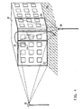
- FIG. 2 shows a three-dimensional illustration of the viewing areas 6, 7 of the monitoring devices 1, 2 from FIG. 1.
- the viewing areas 6, 7 are marked with a rectangular base with a base of length 11 shown, although in reality these viewing areas 6, 7 will generally be designed as so-called "viewing cones".
- the viewing areas 6, 7 preferably overlap one another in such a way that likewise larger objects, for example, starting from the viewing area 6 into the viewing area 7 occur, also in the overlap area of the viewing areas 6, 7 of the length 10 can be fully captured.
- FIG. 3 shows a top view of the arrangement of the monitoring devices 1, 2 according to FIG Fig. 1 in a first embodiment.
- the monitoring devices 1, 2 serve in the illustrated embodiment for this purpose, for example an unauthorized approach to prevent objects on a runway 12 on an airport site. This will by means of the monitoring devices 1, 2 a control line KL1 is monitored and if a Object starting from a permitted area EB this control line KL1 in the direction of If the taxiway exceeds 12, the alarm is triggered.
- a person or a vehicle along a the control line from the permitted area EB indicated by an arrow 13 KL1 in the direction of the taxiway 12 is exceeded when crossing the control line KL1 in point 16 alarm triggered.
- the corresponding object first enters the Viewing area 6 of the monitoring device 1 and then crosses this viewing area 6 and the overlap area that this viewing area 6 with the viewing area 7 of the monitoring device 2 forms.
- the object is registered at the time of its entry Field of view 6 captured by the monitoring device 1 and its movement is determined by means of Object tracking tracks to the point where the object is in the overlap area entry.
- Object tracking means that the entire movement of the object is recorded in the viewing area 6, 7 of the monitoring device 1, 2.
- the object becomes from the monitoring device 1 to the monitoring device 2 by means of so-called “Visual Handover "or object handover and then from the monitoring device 2 continues to point 16 where the alarm is triggered.
- “Visual Handover” or object transfer means that the monitoring device 1 recorded data relating to the object of the monitoring device 2 become.
- a second variant is indicated by means of an arrow 14, which illustrates that again any object such as a person or a vehicle along the direction of the arrow of the arrow 14 moves and the control line KL1 starting from the permitted area EB in the direction of the runway 12. This is when the control line is exceeded KL1 in point 17 alarm triggered.
- the corresponding object enters the viewing area 6 of FIG Monitoring device 1 and leaves this field of view 6 again before entering into the viewing area 7 of the monitoring device 2 and then crossing over the control line 1 in point 17.
- the object enters the viewing area 7 of the monitoring device 2 it is determined that this object has previously covered the viewing area 6 crossed the monitoring device 1, whereupon the object from the monitoring device 1 is transferred to the monitoring device 2.
- a third variant is shown by means of an arrow 15.
- the space between the Control line KL1 and taxiway 12 defined as a restricted area EEB by allowing certain objects to stay.
- the monitoring device In order to prevent such a false alarm from being triggered, the monitoring device must 2 the "history" of the control employee is known, i.e. in the present example the path taken by the control personnel along arrow 15 in the field of vision 6 has covered the monitoring device 1. Accordingly, object tracking of the control employee in both viewing areas 6, 7, and the monitoring device 1 and the monitoring device 2, when making a decision is taken into account, it can be determined that the control employee leaves the Intermediate space has crossed the control line KL1 and then again by crossing the control line KL1 has returned to this space. That means it can it is found that in the present example no alarm is triggered because the exceeding the control line KL1 is a justified crossing.
- Another major advantage of handing over the property is that the security of detection of objects in the viewing areas 6, 7 of the monitoring devices 1, 2 increased is what is explained in more detail below.
- an object enters the viewing area 6, where it is from the monitoring device 1 is detected and where changes in position of the object are tracked and corresponding Data is recorded.
- the notification preferably includes information regarding the direction in which the object is moving and the recorded data so that the monitoring device 2 can determine which location the object will enter into the viewing area 7. The monitoring device can thus 2 recognize the object more easily when entering the viewing area 7 and to capture.
- the detection and detection of the object by the monitoring devices 1, 2 in each of the viewing areas 6, 7 depends on a predetermined threshold value, which must be exceeded in order to record object data, for example trigger this threshold value in the monitoring device 2 is preferred based on the data sent by the monitoring device 1, so that the detection threshold is lowered accordingly. Lowering the Threshold value can take place for a sub-zone of the viewing area 7, into which the monitoring device 1 detected object is likely to occur, or for the complete Viewing area 7.
- a monitoring device 1, 2 that detects an occurrence of an object in their field of view 6, 7 is detected and changes in position of this object captures, record and analyze data to determine if the object may be from the Field of view 6, 7 of another monitoring device 1, 2 has occurred.
- the corresponding monitoring device 1, 2 can be positively analyzed by the other monitoring device 1, 2 data on the movement of the Request objects in the viewing area 6, 7 of this other monitoring device 1, 2.
- an interfering object such as a spider is located moved over a section of a monitoring device 1, 2 and recognized as an object because this object takes into account its determined direction of movement the viewing area 6, 7 of another monitoring device 1, 2 should come.
- the requesting monitoring device 1, 2 has no data relating to the detected Object received from another monitoring device 1, 2 can be assumed that the detected object is not alarm relevant.
- FIG. 4 shows an illustration of an arrangement of monitoring devices 19, 20 according to a further preferred embodiment of the present invention.
- the monitoring facilities 19, 20 can in turn be used as video surveillance cameras be executed or as infrared or thermal imaging cameras.
- the monitoring facilities 19, 20 are preferably each mounted on masts that are firmly in the ground are anchored.
- the monitoring devices 19, 20 can be connected to any rigid or moving objects, for example on parts of a building.
- the monitoring devices 19, 20 are used, for example, for Supervision of a prison building.
- the monitoring devices 19, 20 are designed as surveillance cameras, both have surveillance cameras each have a viewing area 21, 22.
- the size of the monitorable Viewing area 21, 22 depends on the orientation of the monitoring devices 19, 20, as well as the detection properties of the corresponding monitoring devices 19, 20.
- the detection properties correspond for example the optical properties of the camera optics used.
- the assumption is that an object, such as a security guard, from the roof 18 of the building via a fire escape 25 into an allowed area EB can arrive without triggering an alarm.
- an alarm should be triggered when a Object, such as a breakaway, out of a window 24 into the permitted area EB arrives.
- Fig. 5 shows an illustrative block diagram of an embodiment of an inventive Systems for image evaluation.
- a variety preferably delivers of surveillance cameras 1, 2 video signals, each for monitoring one of the corresponding camera 1, 2 are used for the field of view.
- the video signals from the cameras 1, 2 are each connected to an analog / digital converter 29 and digitized.
- the camera 1, 2 can be a common video surveillance camera or an infrared or Be a thermal imaging camera.
- the digitized pixel data of the video signals of the corresponding cameras 1, 2 are each stored in a storage device 30, a storage device 30 preferably two different image memories or one image memory with two different ones Has storage areas, and wherein in the first image memory or first Memory area the digitized pixel data, which represent a respective current image, be stored and in the second image memory or second memory area digitized pixel data representing a reference image are stored.
- the digitized pixel data of the current image compared to that of the reference image of each video signal to see differences between the two images, each generated by one and the same camera 1, 2 will determine.
- a binary image of a current image is generated in the pixels with the binary value "0" represent pixels whose data are related to the pixel data of the respective Reference images are unchanged, while pixels marked with the binary value "1" Represent pixels, i.e. Pixels of the current image, with their data related to the image data of the reference image a change in image was determined.
- the binary images generated are in an object determination device 32 in each case related marked pixels examined, all connected pixels be assigned to an object, d. H.
- Objects are extracted from the binary images. Accordingly, an object corresponds to a coherent image area that is within a certain one of the storage cycle of the second memory or second Storage area dependent period has changed.
- Object data is stored in an object list of the extracted objects, the objects being stored, for example, as a die maximum horizontal and vertical extent of the marked pixel area circumscribing Rectangle or the like can be defined.
- the current object list is with a stored object list of the previous image compared and updated.
- the object data thus generated are evaluated in an evaluation device 33 Detection of alarm-relevant objects and for triggering an alarm.
- data are preferably calculated, which result from the difference of a detection point, for example, the center of a new object and a saved one Center of an assigned object of the previous image results. Based The current object list can be updated with this data.
- any object can be calculated by computing data, preferably a distance traveled, a horizontal and vertical directional component and one include the average speed of the object based on the previous duration, be used to over a certain object in the field of view of a camera 1, 2 to track the entire period of collection.
- each of the first memory and the first memory area become the object corresponding digitized pixel data is read out, using known image processing methods in the image section read out image content features for the object be extracted.
- the size of the extracted Rectangle and the number of marked pixels found within the rectangle are used.
- Feature criteria that are stored in a storage device 34 are compared and preferably an alarm is triggered if all criteria are met at the same time.
- the camera 1, 2 is selected by means of a selection device 28, in its field of vision the corresponding object is detected, and the corresponding video signal of the Current image of the selected camera 1, 2 is switched to one by means of a switch 48 Monitor 35 switched, with the alarm objects showing the associated vectors become.
- FIG. 6 shows a detailed view of the memory device 30 from FIG. 5.
- the memory device 30 preferably comprises two image memories 36, 37, the digitized ones Pixel data of the current image are stored in the image memory 36. Furthermore periodically, the digitized pixel data in the second Image memory 37 stored in each case until image data is stored again the image memory 37 to be used as a reference image. The digitized pixel data the image memories 36, 37 become 31 in the image difference determination device compared with each other. Furthermore, the digitized pixel data from memory 36 are read out by the evaluation device 33 for feature extraction in relation on alarm-relevant objects.
- FIG. 7 shows a detailed view of the image difference determination device 31 from FIG. 5.
- the image difference determination device 31 preferably comprises a subtraction device 38, an amount formation device 39 and a threshold value comparison device 40th
- the digitized pixel data of the current Image compared with the digitized pixel data of the reference image and for each Differences in corresponding pixels are determined. From these differences amounts are formed for the individual pixels in the amount formation device 39, that are compared in the threshold value comparison device 40 with a predetermined threshold value which represents a decision threshold for a pixel change. By for example, this decision threshold will be changes caused by signal noise are eliminated. If the threshold is exceeded, a binary value is generated "1" generated for the corresponding pixel, i.e. for the pixel was one Image change detected and therefore this pixel is noted or marked. at If the threshold value is undershot, a binary value "0" is assigned to the pixel.
- a binary image, the image changes, can be formed by means of the binary values generated in this way represented in the current image with respect to the reference image.
- FIG. 8 shows a detailed view of the object determination device 32 from FIG. 5
- Object determination device 32 preferably comprises a binary image memory 41, an object extractor 42 and an object correlator 43.
- the binary image stored in the image difference determining means 31 is generated, stored.
- This binary image is generated by the object extractor 42 examined for contiguous and marked pixels in order to extract objects and corresponding object data are stored in an object list.
- a major advantage of determining objects is that in the further Processing no longer individual pixels, only the extracted ones Objects are used, which increases the processing speed considerably.
- the current object list with a stored object list is generated by means of the object correlator 43 compared and updated the previous image, using the one from the current one Binary image extracted objects from the objects found in the previous image be assigned by plausibility check.
- FIG. 9 shows a detailed view of the evaluation device 33 from FIG. 5.
- the evaluation device 33 preferably comprises an object tracking device 44, a Feature extraction device 45 and an alarm object checking device 46.
- the object tracking device 44 calculates data which are used to track an object in the Field of view of a corresponding camera 1, 2 can be used. Furthermore determined the object tracking device 44 in the event that an object covers the viewing area of a Camera 1, 2 leaves whether the object enters the field of view of another camera 1, 2. Thus, the object tracking device 44 can send a signal to the selection device 28 send to cause the video signal of the corresponding camera 1, 2 by means of the switch 48 is switched to the monitor 35,
- the feature extraction device 45 reads the image data in the area of alarm-relevant object rectangles from the first image memory 36 in FIG. 6 and extracts in this image detail according to known image processing methods image content features for a corresponding Object. However, this feature extraction only happens for alarm-relevant objects, i.e. for objects that have a predetermined direction, size, speed, etc.
- the alarm object checking device 46 the features of the extracted and tracked Objects with the required feature criteria stored in storage device 34 compared.
- FIG. 10 shows a block diagram of a further variant of the system according to FIG. 5, in which a reduction stage 47 between the analog / digital converter 29 and the memory device 30 is interposed.
- the reduction stage 47 serves to reduce the amount of data a video signal, for example by adding individual pixel data in groups to new pixel data that are stored in the storage device 30.
- FIG. 11 shows a memory section of the binary image memory 41 from FIG. 8.
- the memory section is shown in the form of a 2-dimensional coordinate system 49 with an x-axis in the horizontal direction and y-axis in the vertical direction.
- Marked pixels are with crosses, i.e. Marked "X".
- the extracted objects are rectangular, whereby object 1, that corresponds to the pixel area 50, has a height H1 and a width B1 and Object 2, which corresponds to the pixel region 51, has a height H2 and a width B2.
- data can be determined that the Coordinates x, y of the corresponding object center, the respective object height H, the represent the respective object width B and the number Px of the binary marked pixels. This data is entered in an object list 52.
- the object has a height of 2 pixels and one Width of 4 pixels and includes a total of 5 marked pixels.
- the 12 shows an updated object list in which the data calculated by the object tracking device 44 has been supplemented.
- the current center of detection of an object is represented by the coordinates x n and y n and the last saved center of the object by the coordinates x n-1 and y n-1 .
- the values H n-1 , B n-1 and Px n-1 indicate the last saved height, width or number of the marked pixels of the object.
- the updated object list is supplemented by the determined values for the amount of a movement vector s, an average speed v, a previous duration T and movement direction components R H and R V.
- Object 1 has, for example, a current center of detection (2; 0).
- the last saved center has the coordinates (3.5, 1.5). According to the Pythagorean Theorem, this results in a distance to:
Landscapes
- Physics & Mathematics (AREA)
- General Physics & Mathematics (AREA)
- Engineering & Computer Science (AREA)
- Computer Vision & Pattern Recognition (AREA)
- Multimedia (AREA)
- Alarm Systems (AREA)
- Closed-Circuit Television Systems (AREA)
- Burglar Alarm Systems (AREA)
- Image Analysis (AREA)
Applications Claiming Priority (2)
| Application Number | Priority Date | Filing Date | Title |
|---|---|---|---|
| DE10042935 | 2000-08-31 | ||
| DE2000142935 DE10042935B4 (de) | 2000-08-31 | 2000-08-31 | Verfahren zum Überwachen eines vorbestimmten Bereichs und entsprechendes System |
Publications (3)
| Publication Number | Publication Date |
|---|---|
| EP1189187A2 true EP1189187A2 (fr) | 2002-03-20 |
| EP1189187A3 EP1189187A3 (fr) | 2009-05-27 |
| EP1189187B1 EP1189187B1 (fr) | 2016-02-03 |
Family
ID=7654518
Family Applications (1)
| Application Number | Title | Priority Date | Filing Date |
|---|---|---|---|
| EP01119125.1A Expired - Lifetime EP1189187B1 (fr) | 2000-08-31 | 2001-08-08 | Procédé et système de surveillance d'une zône prédéterminée |
Country Status (4)
| Country | Link |
|---|---|
| EP (1) | EP1189187B1 (fr) |
| DE (1) | DE10042935B4 (fr) |
| ES (1) | ES2563452T3 (fr) |
| NO (1) | NO329869B1 (fr) |
Cited By (13)
| Publication number | Priority date | Publication date | Assignee | Title |
|---|---|---|---|---|
| WO2004045215A1 (fr) * | 2002-11-12 | 2004-05-27 | Intellivid Corporation | Procede et systeme pour la localisation et la surveillance de comportement d'objets multiples se deplaçant a travers une pluralite de champ de vision |
| EP1613084A2 (fr) * | 2004-06-29 | 2006-01-04 | Videra Oy | Système AV et dispositif de commande |
| US7221775B2 (en) | 2002-11-12 | 2007-05-22 | Intellivid Corporation | Method and apparatus for computerized image background analysis |
| US7280673B2 (en) | 2003-10-10 | 2007-10-09 | Intellivid Corporation | System and method for searching for changes in surveillance video |
| US7286157B2 (en) | 2003-09-11 | 2007-10-23 | Intellivid Corporation | Computerized method and apparatus for determining field-of-view relationships among multiple image sensors |
| US7346187B2 (en) | 2003-10-10 | 2008-03-18 | Intellivid Corporation | Method of counting objects in a monitored environment and apparatus for the same |
| EP1772833A4 (fr) * | 2004-08-05 | 2008-11-12 | Matsushita Electric Industrial Co Ltd | Dispositif de surveillance et son programme |
| US7671728B2 (en) | 2006-06-02 | 2010-03-02 | Sensormatic Electronics, LLC | Systems and methods for distributed monitoring of remote sites |
| US7825792B2 (en) | 2006-06-02 | 2010-11-02 | Sensormatic Electronics Llc | Systems and methods for distributed monitoring of remote sites |
| EP2120452A4 (fr) * | 2007-02-14 | 2011-05-18 | Panasonic Corp | Caméra de surveillance et procédé de commande de caméra de surveillance |
| US8174572B2 (en) | 2005-03-25 | 2012-05-08 | Sensormatic Electronics, LLC | Intelligent camera selection and object tracking |
| US9036028B2 (en) | 2005-09-02 | 2015-05-19 | Sensormatic Electronics, LLC | Object tracking and alerts |
| WO2017060083A1 (fr) * | 2015-10-06 | 2017-04-13 | Philips Lighting Holding B.V. | Système de comptage de personnes et d'éclairage intégré |
Families Citing this family (1)
| Publication number | Priority date | Publication date | Assignee | Title |
|---|---|---|---|---|
| DE10310636A1 (de) * | 2003-03-10 | 2004-09-30 | Mobotix Ag | Überwachungsvorrichtung |
Family Cites Families (4)
| Publication number | Priority date | Publication date | Assignee | Title |
|---|---|---|---|---|
| GB2183878B (en) * | 1985-10-11 | 1989-09-20 | Matsushita Electric Works Ltd | Abnormality supervising system |
| CA2155719C (fr) * | 1994-11-22 | 2005-11-01 | Terry Laurence Glatt | Systeme de surveillance video avec cameras pilotes et asservies |
| GB2337146B (en) * | 1998-05-08 | 2000-07-19 | Primary Image Limited | Method and apparatus for detecting motion across a surveillance area |
| US6359647B1 (en) * | 1998-08-07 | 2002-03-19 | Philips Electronics North America Corporation | Automated camera handoff system for figure tracking in a multiple camera system |
-
2000
- 2000-08-31 DE DE2000142935 patent/DE10042935B4/de not_active Expired - Lifetime
-
2001
- 2001-08-08 ES ES01119125.1T patent/ES2563452T3/es not_active Expired - Lifetime
- 2001-08-08 EP EP01119125.1A patent/EP1189187B1/fr not_active Expired - Lifetime
- 2001-08-27 NO NO20014158A patent/NO329869B1/no not_active IP Right Cessation
Cited By (24)
| Publication number | Priority date | Publication date | Assignee | Title |
|---|---|---|---|---|
| WO2004045215A1 (fr) * | 2002-11-12 | 2004-05-27 | Intellivid Corporation | Procede et systeme pour la localisation et la surveillance de comportement d'objets multiples se deplaçant a travers une pluralite de champ de vision |
| US7221775B2 (en) | 2002-11-12 | 2007-05-22 | Intellivid Corporation | Method and apparatus for computerized image background analysis |
| US7460685B2 (en) | 2002-11-12 | 2008-12-02 | Intellivid Corporation | Method and apparatus for computerized image background analysis |
| US8547437B2 (en) | 2002-11-12 | 2013-10-01 | Sensormatic Electronics, LLC | Method and system for tracking and behavioral monitoring of multiple objects moving through multiple fields-of-view |
| US7286157B2 (en) | 2003-09-11 | 2007-10-23 | Intellivid Corporation | Computerized method and apparatus for determining field-of-view relationships among multiple image sensors |
| US7280673B2 (en) | 2003-10-10 | 2007-10-09 | Intellivid Corporation | System and method for searching for changes in surveillance video |
| US7346187B2 (en) | 2003-10-10 | 2008-03-18 | Intellivid Corporation | Method of counting objects in a monitored environment and apparatus for the same |
| EP1613084A2 (fr) * | 2004-06-29 | 2006-01-04 | Videra Oy | Système AV et dispositif de commande |
| EP1772833A4 (fr) * | 2004-08-05 | 2008-11-12 | Matsushita Electric Industrial Co Ltd | Dispositif de surveillance et son programme |
| US8174572B2 (en) | 2005-03-25 | 2012-05-08 | Sensormatic Electronics, LLC | Intelligent camera selection and object tracking |
| US8502868B2 (en) | 2005-03-25 | 2013-08-06 | Sensormatic Electronics, LLC | Intelligent camera selection and object tracking |
| US9407878B2 (en) | 2005-09-02 | 2016-08-02 | Sensormatic Electronics, LLC | Object tracking and alerts |
| US9036028B2 (en) | 2005-09-02 | 2015-05-19 | Sensormatic Electronics, LLC | Object tracking and alerts |
| US9881216B2 (en) | 2005-09-02 | 2018-01-30 | Sensormatic Electronics, LLC | Object tracking and alerts |
| US8013729B2 (en) | 2006-06-02 | 2011-09-06 | Sensormatic Electronics, LLC | Systems and methods for distributed monitoring of remote sites |
| US7825792B2 (en) | 2006-06-02 | 2010-11-02 | Sensormatic Electronics Llc | Systems and methods for distributed monitoring of remote sites |
| US7671728B2 (en) | 2006-06-02 | 2010-03-02 | Sensormatic Electronics, LLC | Systems and methods for distributed monitoring of remote sites |
| US9286775B2 (en) | 2007-02-14 | 2016-03-15 | Panasonic Intellectual Property Management Co., Ltd. | Monitoring camera and monitoring camera control method |
| US9437089B2 (en) | 2007-02-14 | 2016-09-06 | Panasonic Intellectual Property Management Co., Ltd. | Monitoring camera and monitoring camera control method |
| US9870685B2 (en) | 2007-02-14 | 2018-01-16 | Panasonic Intellectual Property Management Co., Ltd. | Monitoring camera and monitoring camera control method |
| EP2120452A4 (fr) * | 2007-02-14 | 2011-05-18 | Panasonic Corp | Caméra de surveillance et procédé de commande de caméra de surveillance |
| US10475312B2 (en) | 2007-02-14 | 2019-11-12 | Panasonic intellectual property Management co., Ltd | Monitoring camera and monitoring camera control method |
| US10861304B2 (en) | 2007-02-14 | 2020-12-08 | Panasonic I-Pro Sensing Solutions Co., Ltd. | Monitoring camera and monitoring camera control method |
| WO2017060083A1 (fr) * | 2015-10-06 | 2017-04-13 | Philips Lighting Holding B.V. | Système de comptage de personnes et d'éclairage intégré |
Also Published As
| Publication number | Publication date |
|---|---|
| NO329869B1 (no) | 2011-01-17 |
| NO20014158L (no) | 2002-03-01 |
| DE10042935B4 (de) | 2005-07-21 |
| DE10042935A1 (de) | 2002-03-14 |
| EP1189187B1 (fr) | 2016-02-03 |
| ES2563452T3 (es) | 2016-03-15 |
| NO20014158D0 (no) | 2001-08-27 |
| EP1189187A3 (fr) | 2009-05-27 |
Similar Documents
| Publication | Publication Date | Title |
|---|---|---|
| DE60034555T2 (de) | System zur objekterkennung und -verfolgung | |
| DE112010003000B4 (de) | Sichtsystem zum Überwachen von Menschen in dynamischen Umgebungen | |
| EP0853299B1 (fr) | Procédé et dispositif de commande d'un aménagement pour porte en réponse à la présence des personnes | |
| DE69622476T2 (de) | Verfahren und Gerät zur Objekterkennung innerhalb des Gesichtfeldes eines Abbildungsgerätes | |
| EP1189187B1 (fr) | Procédé et système de surveillance d'une zône prédéterminée | |
| DE102008039130A1 (de) | Durch ein neurales Netzwerk gesteuertes automatisches Verfolgungs- und Erkennungssystem und Verfahren | |
| EP0815539B1 (fr) | Procede pour detecter des objets en mouvement dans des images se succedant dans le temps | |
| DE602005001627T2 (de) | Vorrichtung zur Extraktion von Fussgängern | |
| EP2174260A2 (fr) | Dispositif pour identifier et/ou classifier des modèles de mouvements dans une séquence d'images d'une scène de surveillance, procédé et programme informatique | |
| DE69738287T2 (de) | Verfahren zum Anzeigen eines sich bewegenden Objekts, dessen Bahn zu identifizieren ist, Anzeigesystem unter Verwendung dieses Verfahrens und Programmaufzeichnungsmedium dafür | |
| DE4410406A1 (de) | Vorrichtung zum Überwachen der Umgebung eines Fahrzeugs | |
| DE4430016C2 (de) | Bewegungsmelder und ein Verfahren zur Bewegungsmeldung | |
| WO1998040855A1 (fr) | Systeme de surveillance video d'une surface | |
| DE102012215544A1 (de) | Überwachung einer Bahnstrecke | |
| EP2095008A1 (fr) | Procédé et dispositif de surveillance d'un espace à trois dimensions | |
| DE102005026876A1 (de) | Fahrzeugumgebungs-Überwachungsvorrichtung | |
| WO2002054364A2 (fr) | Systeme de detection de fumee base sur la video | |
| DE19621612C2 (de) | Vorrichtung zur Überwachung eines Gleisabschnittes in einem Bahnhof | |
| DE69738270T2 (de) | Erfassungssystem | |
| DE102018008282A1 (de) | Vorrichtung und Verfahren zum Erfassen von Flugobjekten | |
| DE10049366A1 (de) | Verfahren zum Überwachen eines Sicherheitsbereichs und entsprechendes System | |
| DE19937928B4 (de) | Einrichtung zum Erkennen eines beweglichen Körpers und Einrichtung zum Überwachen eines Kraftfahrzeugs | |
| EP1026632B1 (fr) | Systeme et procede d'evaluation d'image | |
| DE19956266A1 (de) | Überwachungsanlage | |
| DE102007033133A1 (de) | Verfahren und Vorrichtung zur Detektion von Objekten |
Legal Events
| Date | Code | Title | Description |
|---|---|---|---|
| PUAI | Public reference made under article 153(3) epc to a published international application that has entered the european phase |
Free format text: ORIGINAL CODE: 0009012 |
|
| AK | Designated contracting states |
Kind code of ref document: A2 Designated state(s): AT BE CH CY DE DK ES FI FR GB GR IE IT LI LU MC NL PT SE TR |
|
| AX | Request for extension of the european patent |
Free format text: AL;LT;LV;MK;RO;SI |
|
| PUAL | Search report despatched |
Free format text: ORIGINAL CODE: 0009013 |
|
| AK | Designated contracting states |
Kind code of ref document: A3 Designated state(s): AT BE CH CY DE DK ES FI FR GB GR IE IT LI LU MC NL PT SE TR |
|
| AX | Request for extension of the european patent |
Extension state: AL LT LV MK RO SI |
|
| RIC1 | Information provided on ipc code assigned before grant |
Ipc: H04N 7/18 20060101ALI20090417BHEP Ipc: G08B 13/196 20060101ALI20090417BHEP Ipc: G08B 13/194 20060101ALI20090417BHEP Ipc: G08B 15/00 20060101AFI20020128BHEP |
|
| 17P | Request for examination filed |
Effective date: 20091127 |
|
| AKX | Designation fees paid |
Designated state(s): AT BE CH CY DE DK ES FI FR GB GR IE IT LI LU MC NL PT SE TR |
|
| 17Q | First examination report despatched |
Effective date: 20101229 |
|
| RAP1 | Party data changed (applicant data changed or rights of an application transferred) |
Owner name: SECURITON GMBH |
|
| GRAP | Despatch of communication of intention to grant a patent |
Free format text: ORIGINAL CODE: EPIDOSNIGR1 |
|
| INTG | Intention to grant announced |
Effective date: 20150318 |
|
| GRAS | Grant fee paid |
Free format text: ORIGINAL CODE: EPIDOSNIGR3 |
|
| GRAP | Despatch of communication of intention to grant a patent |
Free format text: ORIGINAL CODE: EPIDOSNIGR1 |
|
| INTG | Intention to grant announced |
Effective date: 20150928 |
|
| GRAA | (expected) grant |
Free format text: ORIGINAL CODE: 0009210 |
|
| AK | Designated contracting states |
Kind code of ref document: B1 Designated state(s): AT BE CH CY DE DK ES FI FR GB GR IE IT LI LU MC NL PT SE TR |
|
| REG | Reference to a national code |
Ref country code: GB Ref legal event code: FG4D Free format text: NOT ENGLISH |
|
| REG | Reference to a national code |
Ref country code: AT Ref legal event code: REF Ref document number: 774012 Country of ref document: AT Kind code of ref document: T Effective date: 20160215 Ref country code: CH Ref legal event code: NV Representative=s name: BOVARD AG, CH Ref country code: CH Ref legal event code: EP |
|
| REG | Reference to a national code |
Ref country code: IE Ref legal event code: FG4D Free format text: LANGUAGE OF EP DOCUMENT: GERMAN |
|
| REG | Reference to a national code |
Ref country code: ES Ref legal event code: FG2A Ref document number: 2563452 Country of ref document: ES Kind code of ref document: T3 Effective date: 20160315 |
|
| REG | Reference to a national code |
Ref country code: DE Ref legal event code: R096 Ref document number: 50116527 Country of ref document: DE |
|
| REG | Reference to a national code |
Ref country code: NL Ref legal event code: FP |
|
| REG | Reference to a national code |
Ref country code: SE Ref legal event code: TRGR |
|
| PG25 | Lapsed in a contracting state [announced via postgrant information from national office to epo] |
Ref country code: FI Free format text: LAPSE BECAUSE OF FAILURE TO SUBMIT A TRANSLATION OF THE DESCRIPTION OR TO PAY THE FEE WITHIN THE PRESCRIBED TIME-LIMIT Effective date: 20160203 Ref country code: IT Free format text: LAPSE BECAUSE OF FAILURE TO SUBMIT A TRANSLATION OF THE DESCRIPTION OR TO PAY THE FEE WITHIN THE PRESCRIBED TIME-LIMIT Effective date: 20160203 |
|
| REG | Reference to a national code |
Ref country code: FR Ref legal event code: PLFP Year of fee payment: 16 |
|
| PG25 | Lapsed in a contracting state [announced via postgrant information from national office to epo] |
Ref country code: PT Free format text: LAPSE BECAUSE OF FAILURE TO SUBMIT A TRANSLATION OF THE DESCRIPTION OR TO PAY THE FEE WITHIN THE PRESCRIBED TIME-LIMIT Effective date: 20160603 |
|
| PG25 | Lapsed in a contracting state [announced via postgrant information from national office to epo] |
Ref country code: DK Free format text: LAPSE BECAUSE OF FAILURE TO SUBMIT A TRANSLATION OF THE DESCRIPTION OR TO PAY THE FEE WITHIN THE PRESCRIBED TIME-LIMIT Effective date: 20160203 |
|
| REG | Reference to a national code |
Ref country code: DE Ref legal event code: R097 Ref document number: 50116527 Country of ref document: DE |
|
| PLBE | No opposition filed within time limit |
Free format text: ORIGINAL CODE: 0009261 |
|
| STAA | Information on the status of an ep patent application or granted ep patent |
Free format text: STATUS: NO OPPOSITION FILED WITHIN TIME LIMIT |
|
| 26N | No opposition filed |
Effective date: 20161104 |
|
| PG25 | Lapsed in a contracting state [announced via postgrant information from national office to epo] |
Ref country code: MC Free format text: LAPSE BECAUSE OF FAILURE TO SUBMIT A TRANSLATION OF THE DESCRIPTION OR TO PAY THE FEE WITHIN THE PRESCRIBED TIME-LIMIT Effective date: 20160203 |
|
| REG | Reference to a national code |
Ref country code: IE Ref legal event code: MM4A |
|
| PG25 | Lapsed in a contracting state [announced via postgrant information from national office to epo] |
Ref country code: IE Free format text: LAPSE BECAUSE OF NON-PAYMENT OF DUE FEES Effective date: 20160808 |
|
| REG | Reference to a national code |
Ref country code: FR Ref legal event code: PLFP Year of fee payment: 17 |
|
| PG25 | Lapsed in a contracting state [announced via postgrant information from national office to epo] |
Ref country code: CY Free format text: LAPSE BECAUSE OF FAILURE TO SUBMIT A TRANSLATION OF THE DESCRIPTION OR TO PAY THE FEE WITHIN THE PRESCRIBED TIME-LIMIT Effective date: 20160203 |
|
| PG25 | Lapsed in a contracting state [announced via postgrant information from national office to epo] |
Ref country code: GR Free format text: LAPSE BECAUSE OF FAILURE TO SUBMIT A TRANSLATION OF THE DESCRIPTION OR TO PAY THE FEE WITHIN THE PRESCRIBED TIME-LIMIT Effective date: 20160203 Ref country code: TR Free format text: LAPSE BECAUSE OF FAILURE TO SUBMIT A TRANSLATION OF THE DESCRIPTION OR TO PAY THE FEE WITHIN THE PRESCRIBED TIME-LIMIT Effective date: 20160203 |
|
| REG | Reference to a national code |
Ref country code: FR Ref legal event code: PLFP Year of fee payment: 18 |
|
| PGFP | Annual fee paid to national office [announced via postgrant information from national office to epo] |
Ref country code: NL Payment date: 20200826 Year of fee payment: 20 |
|
| PGFP | Annual fee paid to national office [announced via postgrant information from national office to epo] |
Ref country code: DE Payment date: 20200827 Year of fee payment: 20 Ref country code: ES Payment date: 20200902 Year of fee payment: 20 Ref country code: GB Payment date: 20200826 Year of fee payment: 20 Ref country code: FR Payment date: 20200826 Year of fee payment: 20 Ref country code: LU Payment date: 20200820 Year of fee payment: 20 |
|
| PGFP | Annual fee paid to national office [announced via postgrant information from national office to epo] |
Ref country code: CH Payment date: 20200826 Year of fee payment: 20 Ref country code: AT Payment date: 20200824 Year of fee payment: 20 Ref country code: BE Payment date: 20200825 Year of fee payment: 20 Ref country code: SE Payment date: 20200826 Year of fee payment: 20 |
|
| REG | Reference to a national code |
Ref country code: DE Ref legal event code: R071 Ref document number: 50116527 Country of ref document: DE |
|
| REG | Reference to a national code |
Ref country code: NL Ref legal event code: MK Effective date: 20210807 |
|
| REG | Reference to a national code |
Ref country code: CH Ref legal event code: PL |
|
| REG | Reference to a national code |
Ref country code: GB Ref legal event code: PE20 Expiry date: 20210807 |
|
| REG | Reference to a national code |
Ref country code: AT Ref legal event code: MK07 Ref document number: 774012 Country of ref document: AT Kind code of ref document: T Effective date: 20210808 |
|
| REG | Reference to a national code |
Ref country code: SE Ref legal event code: EUG |
|
| REG | Reference to a national code |
Ref country code: BE Ref legal event code: MK Effective date: 20210808 |
|
| REG | Reference to a national code |
Ref country code: ES Ref legal event code: FD2A Effective date: 20211126 |
|
| PG25 | Lapsed in a contracting state [announced via postgrant information from national office to epo] |
Ref country code: GB Free format text: LAPSE BECAUSE OF EXPIRATION OF PROTECTION Effective date: 20210807 |
|
| PG25 | Lapsed in a contracting state [announced via postgrant information from national office to epo] |
Ref country code: ES Free format text: LAPSE BECAUSE OF EXPIRATION OF PROTECTION Effective date: 20210809 |