EP1193390A2 - Système d'alimentation de carburant pour un moteur à combustion interne - Google Patents
Système d'alimentation de carburant pour un moteur à combustion interne Download PDFInfo
- Publication number
- EP1193390A2 EP1193390A2 EP01120454A EP01120454A EP1193390A2 EP 1193390 A2 EP1193390 A2 EP 1193390A2 EP 01120454 A EP01120454 A EP 01120454A EP 01120454 A EP01120454 A EP 01120454A EP 1193390 A2 EP1193390 A2 EP 1193390A2
- Authority
- EP
- European Patent Office
- Prior art keywords
- feed pump
- fuel
- pump
- supply device
- fuel supply
- Prior art date
- Legal status (The legal status is an assumption and is not a legal conclusion. Google has not performed a legal analysis and makes no representation as to the accuracy of the status listed.)
- Withdrawn
Links
- 239000000446 fuel Substances 0.000 title claims abstract description 70
- 238000002485 combustion reaction Methods 0.000 title claims abstract description 30
- 238000002347 injection Methods 0.000 claims abstract description 7
- 239000007924 injection Substances 0.000 claims abstract description 7
- 238000003860 storage Methods 0.000 claims description 5
- 239000012528 membrane Substances 0.000 description 5
- 239000002826 coolant Substances 0.000 description 2
- 238000004519 manufacturing process Methods 0.000 description 2
- 238000010276 construction Methods 0.000 description 1
- 230000001419 dependent effect Effects 0.000 description 1
- 238000001514 detection method Methods 0.000 description 1
- 238000011161 development Methods 0.000 description 1
- 230000018109 developmental process Effects 0.000 description 1
- 238000005461 lubrication Methods 0.000 description 1
- 238000007726 management method Methods 0.000 description 1
- 238000000034 method Methods 0.000 description 1
- 238000005086 pumping Methods 0.000 description 1
- 238000011144 upstream manufacturing Methods 0.000 description 1
Images
Classifications
-
- F—MECHANICAL ENGINEERING; LIGHTING; HEATING; WEAPONS; BLASTING
- F02—COMBUSTION ENGINES; HOT-GAS OR COMBUSTION-PRODUCT ENGINE PLANTS
- F02M—SUPPLYING COMBUSTION ENGINES IN GENERAL WITH COMBUSTIBLE MIXTURES OR CONSTITUENTS THEREOF
- F02M37/00—Apparatus or systems for feeding liquid fuel from storage containers to carburettors or fuel-injection apparatus; Arrangements for purifying liquid fuel specially adapted for, or arranged on, internal-combustion engines
- F02M37/04—Feeding by means of driven pumps
- F02M37/18—Feeding by means of driven pumps characterised by provision of main and auxiliary pumps
-
- F—MECHANICAL ENGINEERING; LIGHTING; HEATING; WEAPONS; BLASTING
- F02—COMBUSTION ENGINES; HOT-GAS OR COMBUSTION-PRODUCT ENGINE PLANTS
- F02M—SUPPLYING COMBUSTION ENGINES IN GENERAL WITH COMBUSTIBLE MIXTURES OR CONSTITUENTS THEREOF
- F02M37/00—Apparatus or systems for feeding liquid fuel from storage containers to carburettors or fuel-injection apparatus; Arrangements for purifying liquid fuel specially adapted for, or arranged on, internal-combustion engines
- F02M37/04—Feeding by means of driven pumps
- F02M37/041—Arrangements for driving gear-type pumps
Definitions
- the invention is based on one Fuel supply device for an internal combustion engine according to the preamble of claim 1.
- Such a fuel supply device is from the Literature, Diesel engine management, Vieweg publishing house, 2nd edition 1998, pages 262 and 263.
- This Fuel supply device has a feed pump, through the fuel from a reservoir to one High pressure pump is promoted. Through the high pressure pump Fuel under high pressure at least indirectly Injection points promoted on the internal combustion engine.
- the Feed pump is mechanically driven by the internal combustion engine driven. When the engine is started, the Feed pump thus driven only at low speed, so that the amount of fuel delivered by this below Under certain circumstances it is not sufficient to start the To enable internal combustion engine.
- the feed pump does not have sufficient fuel promoted.
- the feed pump could be modified in this way that it delivers more fuel, but then under different operating conditions the amount of fuel delivered would be too large and useless would have to be taxed.
- the fuel supply device with the features according to claim 1, in contrast, has the advantage that by the electrically driven further feed pump targeted at the required operating conditions High-pressure pump supplied fuel quantity can be increased can, so that a safe start and safe operation the internal combustion engine under all operating conditions is guaranteed.
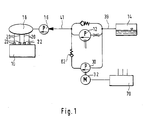
- FIG. 1 shows a Fuel supply device for an internal combustion engine in a schematic representation
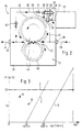
- Figure 2 is a conveyor module
- Figure 3 is a map of the by pumping the Delivery module delivered fuel quantity depending on the Rotational speed.
- FIG 1 is a fuel supply device for an internal combustion engine 10 of a motor vehicle or a stationary engine shown, the particular is a self-igniting internal combustion engine.
- the Fuel supply device has a feed pump 12 on, through which fuel from a reservoir 14 is promoted.
- the feed pump 12 can, for example, as Gear pump to be designed and is mechanically by the Internal combustion engine 10 driven.
- the speed of the Feed pump 12 is proportional to the speed of the Internal combustion engine 10.
- Downstream after the feed pump 12 a high pressure pump 16 is arranged, the suction side of the fuel delivered by the feed pump 12 is supplied.
- a high-pressure accumulator is located downstream of the high-pressure pump 16 18 arranged from which lines 20 to injection points 22 lead away on the cylinders of the internal combustion engine 10.
- injectors which Fuel into the combustion chambers of the cylinders Inject internal combustion engine 10.
- valves 21 are provided, through which the connection of the injectors with the High-pressure accumulator 18 can be opened and separated.
- a high pressure pump is provided whose suction side is connected to the feed pump 12.
- a further feed pump 30 provided that has an electric drive 32.
- the Drive 32 is preferably a direct current electric motor wherein the on-board voltage source of the motor vehicle as Voltage source is used.
- the mechanically driven feed pump 12 and the other Feed pump 30 are preferably to a feed module 34 summarized.
- the conveyor module 34 is enlarged in FIG. 2 shown.
- the conveyor module 34 has a housing 36 with a suction-side connection 38 on which a suction line 39 to Storage container 14 is connected. Is on the housing 36 in addition, a pressure-side connection 40 is arranged on the a pressure line 41 connected to the high pressure pump 16 is.
- a pressure-side connection 40 is arranged on the a pressure line 41 connected to the high pressure pump 16 is.
- the housing 36 is a for the feed pump 12 Pump chamber 42 limited in the as part of the Feed pump 12 two on their outer circumference Intermeshing gears 44 are arranged, one of which is in not shown by the internal combustion engine 10 is driven. When operating the feed pump 12 is by their rotating gears 44 along on their circumference extending delivery channels 46 fuel from the suction side with the suction port 38 to the pressure side with the pressure port 40 promoted.
- the further feed pump 30 is, for example, as Diaphragm pump is formed and has a in the housing 36 in a further pump chamber 48 arranged membrane 50.
- the membrane 50 is connected to a plunger 52, which by the electric motor 32 is driven in one stroke.
- the electric motor 32 can be arranged in the housing 36 or as shown in Figure 2 outside the housing 36, wherein a shaft 54 of the electric motor 32 projects into the housing 36 and is coupled to the plunger 52 via an eccentric 55, so that when the shaft 54 rotates, the plunger 52 in the lifting movement is driven. The lifting movement of the Ram 52 is transferred to membrane 50.
- the Membrane 50 becomes a pump work space in pump chamber 48 56 limited, the one running in the housing 36 Connection 57, for example in the form of a hole or a channel to which suction port 38 is connected.
- Connection 57 is an opening into the pump work space 56
- Check valve 58 arranged during the suction stroke of the membrane 50 is open so that fuel from the suction port 38 in can reach the pump workspace 56.
- the Pump workspace 56 is also via a in the housing 36th extending connection 60, again for example in the form a bore or a channel with the pressure connection 40 connected.
- a connection to the pressure connection 40 is in the connection 60 non-return valve 61 arranged.
- the check valve 61 is preferably in the connection 60 is arranged near the pump work space 56.
- the plunger 52, the diaphragm 50 and the check valves 58 and 61, together with a receiving one Housing part form a structural unit for itself, which in the Housing 36 of the conveyor module 34 is inserted.
- In the Connection 60 of the pump workspace 56 with the Pressure port 40 may be another near the pressure port 40 opening to the pressure connection 40 and to the pump work space 56 closing check valve 62 may be arranged.
- the check valve 62 prevents the Feed pump 12 delivered fuel through the connection 60 into the pump work space 56 of the further feed pump 30 is ousted.
- the operation of the further feed pump 30 is preferred controlled by an electronic control device 70, through which, for example, the injection of the Fuel is controlled with the injectors.
- the Control device 70 are signals about the operating state fed to the internal combustion engine 10, in particular via its Speed, load, coolant temperature, fuel temperature and possibly other parameters. Through the The control device 70 becomes the further feed pump 30 especially at low speed and / or at high Coolant and / or fuel temperature in operation set. A low engine 10 speed is particularly present when starting, so that by the Control device 70 the further feed pump 30 when starting the engine 10 is operated when the Feed pump 12 due to the low speed of the Internal combustion engine 10 also only at low speed is operated.
- the further Feed pump 30 through the control device 70 before the start of the internal combustion engine 10 started is, so that the high pressure pump 16 early Fuel is supplied. This will make a good one Lubrication of the high pressure pump 16 reached. It can it can be provided, for example, that the control device 70 a signal about unlocking the doors of the Motor vehicle is supplied or via the introduction of the Ignition key in the ignition lock or turning the Ignition key in an ignition position or Seat occupancy detection and in this case already another feed pump 30 is put into operation. If the Internal combustion engine 10 a sufficiently high speed has reached, for example, the proper one Idle speed, the control device 70 further feed pump 30 switched on, so that then only the feed pump 12 delivers fuel to the high pressure pump 16.
- the feed pump 12 when the engine 10 is not could be operated by the control device 70 the further feed pump 30 is started, whereby a sufficient amount of fuel to the high pressure pump 16 is funded to at least one emergency operation of the To enable internal combustion engine 10 with low power.
- the further Feed pump 30 is started after the Storage container 14 completely emptied and then again was filled. This will vent and fill the Lines 39 and 41 to the high pressure pump 16 reached, see above that this when starting the Internal combustion engine 10 is already filled with fuel and the starting process can be shortened.
- FIG 3 a map of a fuel delivery rate is over shown the speed of the feed pump 12, the specified numerical values are only examples.
- the High pressure pump 16 has a fuel temperature of about -20 ° C a fuel requirement with the point A is marked and at a fuel temperature of about + 90 ° C a fuel requirement marked with point B. is.
- the delivery rate V 'above the pump speed np at entered a fuel temperature of about -20 ° C and designated with C. It is also another characteristic for a fuel temperature of about + 90 ° C entered and with D designated. From Figure 3 it is clear that the Fuel delivery by the feed pump 12 only from one certain minimum speed npmin of the feed pump 12 begins, which increases with increasing fuel temperature.
- the pumped by the further feed pump 30 The amount of fuel is significantly less than that of the Delivery pump 12 delivered maximum fuel delivery.
- the Delivery rate of the further fuel pump 30 can for example between about 3% and 20% of the maximum Flow rate of the feed pump 12 amount.
- the further one Feed pump 30 is only in for a short period of time Operation so that this is only relative to a corresponding short life span needs to be designed, what a enables cost-effective production. By using it the further feed pump 30 can also be the feed pump 12 themselves are made easier by this larger manufacturing tolerances can be accepted the delivery rate, especially at low pump speeds deteriorate, however, due to the funding of the another feed pump 30 is compensated.
- the further one Feed pump 30 can also be used as a separate unit Feed pump 12 may be formed.
- the further Feed pump 30 of the feed pump 12 also in series Storage container 14 may be connected upstream.
Landscapes
- Engineering & Computer Science (AREA)
- Chemical & Material Sciences (AREA)
- Combustion & Propulsion (AREA)
- Mechanical Engineering (AREA)
- General Engineering & Computer Science (AREA)
- Fuel-Injection Apparatus (AREA)
Applications Claiming Priority (2)
| Application Number | Priority Date | Filing Date | Title |
|---|---|---|---|
| DE10048247 | 2000-09-29 | ||
| DE10048247A DE10048247A1 (de) | 2000-09-29 | 2000-09-29 | Kraftstoffversorgungseinrichtung für eine Brennkraftmaschine |
Publications (2)
| Publication Number | Publication Date |
|---|---|
| EP1193390A2 true EP1193390A2 (fr) | 2002-04-03 |
| EP1193390A3 EP1193390A3 (fr) | 2003-03-19 |
Family
ID=7658065
Family Applications (1)
| Application Number | Title | Priority Date | Filing Date |
|---|---|---|---|
| EP01120454A Withdrawn EP1193390A3 (fr) | 2000-09-29 | 2001-08-28 | Système d'alimentation de carburant pour un moteur à combustion interne |
Country Status (4)
| Country | Link |
|---|---|
| US (1) | US6543425B2 (fr) |
| EP (1) | EP1193390A3 (fr) |
| JP (1) | JP2002155824A (fr) |
| DE (1) | DE10048247A1 (fr) |
Families Citing this family (17)
| Publication number | Priority date | Publication date | Assignee | Title |
|---|---|---|---|---|
| DE19963719A1 (de) * | 1999-12-29 | 2001-07-12 | Bosch Gmbh Robert | Kraftstoffversorgungssystem für eine Brennkraftmaschine mit hybrid angetriebener Kraftstoffpumpe |
| DE10057786A1 (de) * | 2000-11-22 | 2002-06-06 | Siemens Ag | Einspritzsystem für eine Brennkraftmaschine und Verfahren zum Regeln und/oder Entlüften eines solchen Einspritzsystems |
| DE10153396A1 (de) * | 2001-11-01 | 2003-05-28 | Siemens Ag | Einrichtung zur Ansteuerung einer elektrischen Kraftstoffpumpe |
| JP4090382B2 (ja) * | 2003-04-21 | 2008-05-28 | 株式会社日立製作所 | 筒内噴射式内燃機関の燃料供給装置 |
| US6817343B1 (en) * | 2003-04-23 | 2004-11-16 | Caterpillar Inc. | Electronic control system for fuel system priming |
| JP4415275B2 (ja) * | 2006-03-23 | 2010-02-17 | 株式会社デンソー | 燃料供給装置 |
| JP2010007572A (ja) * | 2008-06-27 | 2010-01-14 | Denso Corp | 燃料供給装置 |
| DE102008041067A1 (de) * | 2008-08-07 | 2010-02-11 | Robert Bosch Gmbh | Druckpumpenvorrichtung für ein Hybridfahrzeug |
| SE534873C2 (sv) * | 2010-06-22 | 2012-01-31 | Scania Cv Ab | Bränslesystem för insprutning av en bränsleblandning i en förbränningsmotor |
| CN102734014A (zh) * | 2012-06-19 | 2012-10-17 | 浙江大学 | 一种柴油车高压燃油供给装置 |
| US20140174409A1 (en) * | 2012-12-21 | 2014-06-26 | United Techologies Corporation | Gear Pump Protection Valve |
| SE537002C2 (sv) * | 2013-03-22 | 2014-11-25 | Scania Cv Ab | Bränslesystem för förbränningsmotor och ett förfarande för att reglera ett bränslesystem |
| DE202014010614U1 (de) * | 2014-01-29 | 2016-02-02 | Hemscheidt Fahrwerktechnik Gmbh & Co. Kg | Spanneinrichtung und Bauteil mit einer derartigen Spanneinrichtung |
| JP6387905B2 (ja) * | 2015-06-10 | 2018-09-12 | 株式会社デンソー | ガソリン燃料供給システム |
| US11236682B2 (en) * | 2018-02-22 | 2022-02-01 | Hamilton Sundstrand Corporation | Fuel pump systems for turbomachines |
| IT201900021945A1 (it) * | 2019-11-22 | 2021-05-22 | Bosch Gmbh Robert | Gruppo di pompaggio per alimentare combustibile, preferibilmente gasolio, ad un motore a combustione interna |
| US11629643B1 (en) * | 2022-01-07 | 2023-04-18 | Hamilton Sundstrand Corporation | Fuel pump systems |
Citations (1)
| Publication number | Priority date | Publication date | Assignee | Title |
|---|---|---|---|---|
| DE1064290B (de) * | 1957-02-05 | 1959-08-27 | Daimler Benz Ag | Kraftstoffoerderanlage fuer Brennkraftmaschinen, insbesondere in Kraftfahrzeugen |
Family Cites Families (12)
| Publication number | Priority date | Publication date | Assignee | Title |
|---|---|---|---|---|
| DE754809C (de) * | 1939-09-02 | 1954-04-05 | Pallas App G M B H | Einrichtung zur Brennstoffoerderung mit zwei in einem Aggregat vereinigten Pumpen |
| DE1046402B (de) * | 1955-12-31 | 1958-12-11 | Daimler Benz Ag | Kraftstoffoerderanlage fuer elektrisch anlassbare Brennkraftmaschinen |
| DE3247915A1 (de) * | 1982-12-24 | 1984-07-12 | Robert Bosch Gmbh, 7000 Stuttgart | Kraftstoffoerderanlage fuer brennkraftmaschinen, insbesondere in kraftfahrzeugen |
| US4683854A (en) * | 1985-02-15 | 1987-08-04 | Teledyne Industries, Inc. | Electronic and mechanical fuel supply system |
| JPH04175479A (ja) * | 1990-11-08 | 1992-06-23 | Kanbishi Denki Seizou Kk | ダイヤフラム式電磁ポンプ |
| JP3033214B2 (ja) * | 1991-02-27 | 2000-04-17 | 株式会社デンソー | 複数の燃料圧送手段による蓄圧式燃料供給方法及び装置と、複数の流体圧送手段を有する機器における異常判断装置 |
| JPH07167009A (ja) * | 1993-12-14 | 1995-07-04 | Yamaha Motor Co Ltd | エンジンへの燃料供給装置 |
| JP3333407B2 (ja) * | 1996-10-17 | 2002-10-15 | 株式会社ユニシアジェックス | 直噴式ガソリン内燃機関の燃料供給装置 |
| DE19709737B4 (de) * | 1997-03-10 | 2005-12-22 | Robert Bosch Gmbh | Kraftstofförderanlage für eine Brennkraftmaschine, insbesondere in einem Kraftfahrzeug |
| JP2000352365A (ja) * | 1999-06-10 | 2000-12-19 | Hitachi Constr Mach Co Ltd | エンジンの燃料供給装置 |
| DE19937674B4 (de) * | 1999-08-10 | 2005-02-17 | Siemens Ag | Einspritzanlage für eine Brennkraftmaschine |
| US6253739B1 (en) * | 1999-12-17 | 2001-07-03 | Daimlerchrysler Corporation | Dual function fuel supply module |
-
2000
- 2000-09-29 DE DE10048247A patent/DE10048247A1/de not_active Withdrawn
-
2001
- 2001-08-28 EP EP01120454A patent/EP1193390A3/fr not_active Withdrawn
- 2001-09-21 US US09/960,026 patent/US6543425B2/en not_active Expired - Fee Related
- 2001-09-28 JP JP2001303836A patent/JP2002155824A/ja active Pending
Patent Citations (1)
| Publication number | Priority date | Publication date | Assignee | Title |
|---|---|---|---|---|
| DE1064290B (de) * | 1957-02-05 | 1959-08-27 | Daimler Benz Ag | Kraftstoffoerderanlage fuer Brennkraftmaschinen, insbesondere in Kraftfahrzeugen |
Also Published As
| Publication number | Publication date |
|---|---|
| JP2002155824A (ja) | 2002-05-31 |
| DE10048247A1 (de) | 2002-04-11 |
| US6543425B2 (en) | 2003-04-08 |
| EP1193390A3 (fr) | 2003-03-19 |
| US20020069856A1 (en) | 2002-06-13 |
Similar Documents
| Publication | Publication Date | Title |
|---|---|---|
| EP2032832B1 (fr) | Dispositif d'injection de carburant pour un moteur à combustion interne | |
| EP1193390A2 (fr) | Système d'alimentation de carburant pour un moteur à combustion interne | |
| EP1476654B1 (fr) | Dispositif d'injection de carburant pour moteur a combustion interne | |
| EP1296060B1 (fr) | Système d'injection de carburant pour un moteur à combustion interne | |
| EP2344749B1 (fr) | Pompe haute pression à carburant pour un moteur à combustion interne | |
| EP1702157B1 (fr) | Systeme d'injection de carburant pour un moteur a combustion interne | |
| EP1537325B1 (fr) | Dispositif d'injection de carburant pour moteur a combustion interne | |
| EP2013471B1 (fr) | Dispositif de refoulement de carburant sous haute pression | |
| EP2652294B1 (fr) | Moteur à combustion interne destiné à fonctionner à l'aide d'un carburant liquide et/ou gazeux | |
| EP1126157A2 (fr) | Dispositif d'alimentation en carburant pour un moteur à combustion d'un véhicule | |
| EP1476656B1 (fr) | Dispositif d'injection de carburant pour un moteur a combustion interne | |
| WO2012004084A1 (fr) | Système de carburant pour un moteur à combustion interne | |
| EP1911964B1 (fr) | Pompe à carburant haute pression et système d'injection de carburant pour moteur à combustion interne | |
| EP3014099B1 (fr) | Système d'alimentation de carburant avec vanne de décharge partielle de pression dans la ligne de propulsion d'une pompe à jet | |
| EP1357283A2 (fr) | Dispositif d'injection de carburant pour un moteur à combustion interne | |
| DE102005033638A1 (de) | Kraftstoff-Fördereinrichtung, insbesondere für eine Brennkraftmaschine | |
| DE10237586A1 (de) | Kraftstoffeinspritzeinrichtung für eine Brennkraftmaschine | |
| EP1422416A1 (fr) | Moteur à combustion et méthode pour opérer un moteur à combustion | |
| EP1394403B1 (fr) | Système de combustible pour un moteur à combustion interne | |
| DE10059423A1 (de) | Vorrichtung zum Fördern von Flüssigkeiten, insbesondere Kraftstoff | |
| DE19937674B4 (de) | Einspritzanlage für eine Brennkraftmaschine | |
| DE102018202825B3 (de) | Vorrichtung und Verfahren zum Fördern von Kraftstoff und Additiv | |
| WO2005038236A1 (fr) | Systeme d'injection de carburant pour un moteur a combustion interne | |
| WO2004061293A1 (fr) | Unite d'injection de carburant | |
| WO2009071427A1 (fr) | Dispositif d'injection de carburant dans un moteur à combustion interne |
Legal Events
| Date | Code | Title | Description |
|---|---|---|---|
| PUAI | Public reference made under article 153(3) epc to a published international application that has entered the european phase |
Free format text: ORIGINAL CODE: 0009012 |
|
| AK | Designated contracting states |
Kind code of ref document: A2 Designated state(s): AT BE CH CY DE DK ES FI FR GB GR IE IT LI LU MC NL PT SE TR |
|
| AX | Request for extension of the european patent |
Free format text: AL;LT;LV;MK;RO;SI |
|
| PUAL | Search report despatched |
Free format text: ORIGINAL CODE: 0009013 |
|
| AK | Designated contracting states |
Kind code of ref document: A3 Designated state(s): AT BE CH CY DE DK ES FI FR GB GR IE IT LI LU MC NL PT SE TR Designated state(s): AT BE CH CY DE DK ES FI FR GB GR IE IT LI LU MC NL PT SE TR |
|
| AX | Request for extension of the european patent |
Extension state: AL LT LV MK RO SI |
|
| 17P | Request for examination filed |
Effective date: 20030919 |
|
| AKX | Designation fees paid |
Designated state(s): DE ES FR GB IT |
|
| 17Q | First examination report despatched |
Effective date: 20060607 |
|
| GRAP | Despatch of communication of intention to grant a patent |
Free format text: ORIGINAL CODE: EPIDOSNIGR1 |
|
| STAA | Information on the status of an ep patent application or granted ep patent |
Free format text: STATUS: THE APPLICATION IS DEEMED TO BE WITHDRAWN |
|
| 18D | Application deemed to be withdrawn |
Effective date: 20070228 |