EP1200209B1 - Walzgerüst zum walzen von flachprodukten und verfahren zur regelung der planheit dieser produkte - Google Patents
Walzgerüst zum walzen von flachprodukten und verfahren zur regelung der planheit dieser produkte Download PDFInfo
- Publication number
- EP1200209B1 EP1200209B1 EP00940692A EP00940692A EP1200209B1 EP 1200209 B1 EP1200209 B1 EP 1200209B1 EP 00940692 A EP00940692 A EP 00940692A EP 00940692 A EP00940692 A EP 00940692A EP 1200209 B1 EP1200209 B1 EP 1200209B1
- Authority
- EP
- European Patent Office
- Prior art keywords
- rolls
- roll
- rolling
- working rolls
- rolling stand
- Prior art date
- Legal status (The legal status is an assumption and is not a legal conclusion. Google has not performed a legal analysis and makes no representation as to the accuracy of the status listed.)
- Expired - Lifetime
Links
- 238000005096 rolling process Methods 0.000 title claims abstract description 56
- 238000000034 method Methods 0.000 title claims abstract description 13
- 238000005452 bending Methods 0.000 claims abstract description 27
- 230000007246 mechanism Effects 0.000 claims description 24
- 230000009471 action Effects 0.000 claims description 6
- 230000000694 effects Effects 0.000 claims description 6
- 238000005097 cold rolling Methods 0.000 claims description 4
- 238000005098 hot rolling Methods 0.000 claims description 4
- 238000013519 translation Methods 0.000 abstract description 8
- 230000003068 static effect Effects 0.000 description 4
- 238000003462 Bender reaction Methods 0.000 description 2
- 238000012937 correction Methods 0.000 description 2
- 238000007792 addition Methods 0.000 description 1
- 230000008859 change Effects 0.000 description 1
- 230000008602 contraction Effects 0.000 description 1
- 230000003247 decreasing effect Effects 0.000 description 1
- 230000007547 defect Effects 0.000 description 1
- 230000001419 dependent effect Effects 0.000 description 1
- 238000010586 diagram Methods 0.000 description 1
- 238000006073 displacement reaction Methods 0.000 description 1
- 230000008030 elimination Effects 0.000 description 1
- 238000003379 elimination reaction Methods 0.000 description 1
- 239000002184 metal Substances 0.000 description 1
- 238000012986 modification Methods 0.000 description 1
- 230000004048 modification Effects 0.000 description 1
- 238000012544 monitoring process Methods 0.000 description 1
- 230000008569 process Effects 0.000 description 1
Images



Classifications
-
- B—PERFORMING OPERATIONS; TRANSPORTING
- B21—MECHANICAL METAL-WORKING WITHOUT ESSENTIALLY REMOVING MATERIAL; PUNCHING METAL
- B21B—ROLLING OF METAL
- B21B13/00—Metal-rolling stands, i.e. an assembly composed of a stand frame, rolls, and accessories
- B21B13/02—Metal-rolling stands, i.e. an assembly composed of a stand frame, rolls, and accessories with axes of rolls arranged horizontally
- B21B13/023—Metal-rolling stands, i.e. an assembly composed of a stand frame, rolls, and accessories with axes of rolls arranged horizontally the axis of the rolls being other than perpendicular to the direction of movement of the product, e.g. cross-rolling
-
- B—PERFORMING OPERATIONS; TRANSPORTING
- B21—MECHANICAL METAL-WORKING WITHOUT ESSENTIALLY REMOVING MATERIAL; PUNCHING METAL
- B21B—ROLLING OF METAL
- B21B37/00—Control devices or methods specially adapted for metal-rolling mills or the work produced thereby
- B21B37/28—Control of flatness or profile during rolling of strip, sheets or plates
-
- B—PERFORMING OPERATIONS; TRANSPORTING
- B21—MECHANICAL METAL-WORKING WITHOUT ESSENTIALLY REMOVING MATERIAL; PUNCHING METAL
- B21B—ROLLING OF METAL
- B21B37/00—Control devices or methods specially adapted for metal-rolling mills or the work produced thereby
- B21B37/28—Control of flatness or profile during rolling of strip, sheets or plates
- B21B37/42—Control of flatness or profile during rolling of strip, sheets or plates using a combination of roll bending and axial shifting of the rolls
-
- B—PERFORMING OPERATIONS; TRANSPORTING
- B21—MECHANICAL METAL-WORKING WITHOUT ESSENTIALLY REMOVING MATERIAL; PUNCHING METAL
- B21B—ROLLING OF METAL
- B21B13/00—Metal-rolling stands, i.e. an assembly composed of a stand frame, rolls, and accessories
- B21B13/14—Metal-rolling stands, i.e. an assembly composed of a stand frame, rolls, and accessories having counter-pressure devices acting on rolls to inhibit deflection of same under load; Back-up rolls
- B21B13/142—Metal-rolling stands, i.e. an assembly composed of a stand frame, rolls, and accessories having counter-pressure devices acting on rolls to inhibit deflection of same under load; Back-up rolls by axially shifting the rolls, e.g. rolls with tapered ends or with a curved contour for continuously-variable crown CVC
-
- B—PERFORMING OPERATIONS; TRANSPORTING
- B21—MECHANICAL METAL-WORKING WITHOUT ESSENTIALLY REMOVING MATERIAL; PUNCHING METAL
- B21B—ROLLING OF METAL
- B21B13/00—Metal-rolling stands, i.e. an assembly composed of a stand frame, rolls, and accessories
- B21B13/02—Metal-rolling stands, i.e. an assembly composed of a stand frame, rolls, and accessories with axes of rolls arranged horizontally
- B21B2013/026—Quinto, five high-stands
-
- B—PERFORMING OPERATIONS; TRANSPORTING
- B21—MECHANICAL METAL-WORKING WITHOUT ESSENTIALLY REMOVING MATERIAL; PUNCHING METAL
- B21B—ROLLING OF METAL
- B21B13/00—Metal-rolling stands, i.e. an assembly composed of a stand frame, rolls, and accessories
- B21B13/02—Metal-rolling stands, i.e. an assembly composed of a stand frame, rolls, and accessories with axes of rolls arranged horizontally
- B21B2013/028—Sixto, six-high stands
-
- B—PERFORMING OPERATIONS; TRANSPORTING
- B21—MECHANICAL METAL-WORKING WITHOUT ESSENTIALLY REMOVING MATERIAL; PUNCHING METAL
- B21B—ROLLING OF METAL
- B21B27/00—Rolls, roll alloys or roll fabrication; Lubricating, cooling or heating rolls while in use
- B21B27/02—Shape or construction of rolls
- B21B27/021—Rolls for sheets or strips
- B21B2027/022—Rolls having tapered ends
Definitions
- This invention refers to a rolling stand for plane products, such as strip or similar, and an associated method to control the planarity of said strip.
- the stand is advantageously of the six-high type, with a pair of working rolls (WR) bevelled at least at one end and associated with both negative and positive bending mechanisms and axial displacement, or shifting, mechanisms, a pair of back-up rolls (BUR), and a pair of intermediate rolls (IR) associated with crossing mechanisms.
- WR working rolls
- BUR back-up rolls
- IR intermediate rolls
- the planarity control method provides that the quadratic components, the fourth order components and the edge-drop of the profile of the rolled strip are controlled in a coordinated manner.
- the quadratic and fourth order components can also be controlled with a. high dynamic performance.
- the state of the art includes six-high rolling stands for plane products, comprising a pair of working rolls, a pair of back-up rolls and a pair of intermediate rolls, wherein, to control the planarity of the rolled product both the working rolls and the intermediate rolls are associated with both negative and positive bending systems, and wherein the intermediate rolls are also associated with a system of long axial translation (macro shifting).
- the state of the art also includes a rolling stand wherein the intermediate rolls (IR) are associated with crossing means suitable to reduce the so-called "strip walking".
- IR intermediate rolls
- JP-A-63 002507 discloses a rolling mill for rolling a metal plate comprising a housing, two working rolls, at least one intermediate roll and two back-up rolls.
- Two cylinder rods are abutted on an intermediate roll chock from right and left respectively as an intermediate roll crossing mechanism.
- the intermediate roll is shifted to cross the working roll axis by stretch and, contraction of the two cylinder rods.
- the two working rolls are axially shiftable right and left by means of a general shifting mechanism.
- Increased benders are set on upper and lower working roll chocks and on an intermediate roll chock, respectivelly, while decreased benders are set only on the upper and lower working roll chocks.
- the axial shifting of the working rolls is provided solely to prevent occurrence of local wearing caused by the opposed ends of the plate and to distribute the wear, and the intermediate roll can be bent in only one direction.
- the present Applicant has devised, designed and perfected a rolling stand for plane products and a method to control the planarity of said products according to the invention to overcome the shortcomings described above and to perfect the rolling, stands known in the state of the art.
- One purpose of the invention is to achieve a rolling stand for plane products, such as strip or similar, which will make possible to control and adjust, autonomously and independently, also during rolling, the x 2 component, the x 4 component and also components of a higher order, which consequently makes it possible to control the edge-drop of the rolled product, that is to say, components up to x 10 .
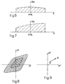
- the thickness is symmetrical, as it should be, the odd components should not be present. At most, we might find the component a 1 x which indicates the presence of strip with a wedge defect, that is, a profile which is on average trapezoid with edges of a different thickness, as shown in Fig. 7.
- Fig. 8 shows two areas, the most extensive of which refers to a system with a higher control capacity than the more inward area.
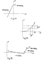
- FIG. 12 shows the control of the crossing of an intermediate roll (IR) according to the invention, wherein it can be noticed how the influence of x 2 has limited collateral effects on x 4 , since the ratio between x 2 and x 4 is about 1/10. Therefore, by acting on IR crossing we have very limited effects on the x 4 component.
- IR intermediate roll
- WR shifting influences both x 2 and x 4 but in a very limited way compared with WR bending and IR crossing.
- WR shifting is practically defined by the width of the strip, with very small adjustments according to the actual edge-drop on the strip at outlet.
- the ratio between x 2 and x 4 is about 1.
- WR bending influences both x 2 and x 4 .
- the ratio x 4 /x 2 depends on the choice of the diameters of the rolls of the stand and on the width of the strip (rolling force, etc.), and is in any case near 1.
- the rolling stand according to the invention is equipped with means which allow IR crossing, WR shifting and WR bending.
- WR shifting is used to pre-set the working rolls according to the edge-drop.
- the stand according to the invention provides to actuate a shifting action on the working rolls in order to allow an adequate control of the shape of the strip edges for all the strip width values provided for a given rolling stand.
- the working rolls are therefore associated with translation means able to displace them axially one with respect to the other, with a travel which may even reach several tens of centimetres, so as to be able to process plane rolled products with very variable widths.
- the values of maximum and minimum width are respectively of about 1,200 mm and 600 mm, therefore the shifting value "S" is at least 300 ⁇ 350 mm, taking into account a certain value of extra travel.
- the values are respectively about 2,600 mm and 1, 300 mm, therefore the shifting value "S" is at least 650 ⁇ 700 mm.
- IR crossing is used to pre-set the IR to obtain a desired x 2 component.
- IR crossing is obtained by means of a preset actuator which is however used in rolling too, to change the x 2 component and allow, together with WR bending, a total dynamic control.
- IR shifting as in conventional stands, practically has an influence only on x 2 (the x 4 /x 2 ratio is equal to about 1/15), and has an x 2 variation action reduced by about 3-4 times compared with those of IR crossing.
- the comparison is between IR shifting, with a travel for example of about 300 mm and IR crossing with a rotation of up to about 1.5°. Therefore IR crossing is much more efficient.
- IR shifting where it is included, is variable in rolling, with shifting speeds of 1/1000 of rolling speeds to prevent damage to the surfaces of the rolls.
- shifting speeds With a rolling speed of 20 m/sec we have a shifting speed of 20 mm/sec. Therefore, it would take 10 secs to carry out the whole control travel.
- the IR crossing speed is higher, at about 0.1°/sec. Consequently, to have the same x 2 variation corresponding to the whole shifting travel (in the embodiment which includes IR shifting), it is enough to vary the crossing angle by 0.2-0.6°, according to the starting point (Fig. 15).
- crossing is quicker: 0.2-0.6° are varied in 2-6 secs, whereas with IR shifting it needs at least 10 secs to carry out the whole travel and obtain the same effects on the strip.
- a pair of intermediate rolls is located between the pair of working rolls and the pair of back-up rolls, therefore the rolling stand is the six-high type.
- the stand is of the five-high type.
- the bending of each working roll can be both positive and negative
- the working rolls are provided, at least at one end, with bevels appropriately configured so as to control the profile of the edges of the rolled product.
- the crossing mechanism allows to carry out the crossing of each intermediate roll quickly, during the rolling step, since the maximum rotation of the intermediate rolls, compared with the working rolls, is about 1.5° and since the speed of rotation is about 0.1°/sec, the correction operation, which requires to vary the angle by 0.2-0.6°, is carried out in about 2-6 secs.
- the method to control the planarity of the plane rolled product provides a step of monitoring, by sensor means, the profile of the product emerging from the stand, and a step of acting on shifting means and bending means associated with at least one of the working rolls to translate it axially and respectively bend it, and on crossing means associated with the intermediate roll to arrange it with its longitudinal axis inclined, that is, rotated with respect to the longitudinal axes of the working rolls and the back-up rolls.
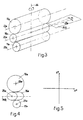
- a rolling stand 10 comprises a pair of working rolls 11a, 11b between which the plane product 12 to be rolled, consisting for example of strip, is able to pass..
- two corresponding back-up rolls 13a, 13b are provided, able to contrast the thrust due to the rolling of the product 12.
- the rolling stand 10 is of the so-called six-high type, and comprises a pair of intermediate rolls 15a, 15b, located between the working rolls 11a, 11b and the back-up rolls 13a, 13b.
- an axial translation mechanism 16, or shifting mechanism is provided, of a conventional type and not shown in detail in the drawings.
- the mechanism 16 is able to displace the corresponding working roll 11a, 11b along the horizontal plane on which its longitudinal axis 21a, 21b lies, thus achieving an axial translation of one working roll 11a with respect to the other 11b.
- the axial translation mechanisms 16 are able to perform a "long" shifting operation, displacing the working rolls 11a and 11b axially one with respect to the other, with a travel which may even be several hundreds of millimetres long, advantageously at least 300 mm, advantageously 350 mm, in the case of cold rolling and in the case of hot rolling, at least 650 mm, advantageously 700 mm.
- a bending mechanism 17 associated with at least one working roll 11a or 11b, but advantageously with both, there is also provided a bending mechanism 17, of a conventional type and not shown in detail in the drawings.
- the mechanism 17 is able to bend the corresponding working roll 11a, 11b in both directions with respect to the horizontal plane on which their longitudinal axis 21a, 21b lies in the inactive condition, and thus obtain a controlled bending both positive and negative.
- the working rolls 11a, 11b are also provided, at least at one end, with bevels 18 suitably configured to control the profile of the edges of the rolled product 12.
- the intermediate rolls 15a, 15b are associated with a crossing mechanism 19, of a conventional type and not shown in detail in the drawings.
- the mechanism 19 is able to incline the intermediate rolls 15a, 15b around a vertical axis 26 (Fig. 3) by a desired angle a in both directions with respect to the working rolls 11a, 11b and back-up rolls 13a, 13b, maintaining their longitudinal axes 23a, 23b on the same horizontal plane PIR parallel to the rolling plane on which the rolled product 12 lies
- Sensor means 27, of a conventional type and not shown in detail in the drawings, are provided near the working rolls 11a, 11b to monitor the profile of the rolled product 12.
- a bending mechanism 20 is also associated with the intermediate rolls 15a, 15b, while no shifting mechanism is associated.
- the bending mechanism 20 is able to bend the corresponding intermediate roll 15a, 15b, in both directions with respect to the horizontal plane PIR on which its longitudinal axis 25a, 25b lies in its inactive condition; the mechanism 20 is thus able to obtain a controlled bending, both positive and negative.
- the double effect bending (positive and negative) achieved by the bending mechanism 17 on the working rolls 11a, 11b is sufficient to allow the fourth order components (x 4 ) to be controlled.
- the long shifting of the working rolls 11a, 11b achieved by the mechanism 16, associated with the presence of the bevels 18 in correspondence with the ends of said working rolls 11a, 11b, allows to control the edge-drop of the rolled product 12.
- the crossing mechanism 19 moreover, allows to carry out the crossing of the intermediate rolls 15a, 15b during the rolling process in a rapid fashion, considering that the maximum rotation of the intermediate rolls 15a, 15b compared with the working rolls 11a, 11b is about 1.5° and that the speed of rotation is in the order of 0.1°/sec.
- the method to control the planarity of the rolled products 12 provides to monitor, by means of sensors 27, the profile of the product 12 emerging from the stand 10, and to act on the mechanisms 16, 17 and 19 and possibly 20 to modify the axial setting and/or the profile (curvature) of the working rolls 11a, 11b, and also the crossing of the intermediate rolls 15a, 15b, and possibly their bending, with respect to the working rolls 11a, 11b.
- a rolling stand 10 is of the so-called five-high type, and comprises only one intermediate roll 15a in the upper section.
- This five-high version allows to simplify the plant, due to the elimination of one intermediate roll and the relative crossing system, and a consequent simplification of the steps of changing the intermediate rolls, at the same time ensuring a field of control which is in any case higher than in six-high stands of a conventional type.
Landscapes
- Engineering & Computer Science (AREA)
- Mechanical Engineering (AREA)
- Control Of Metal Rolling (AREA)
- Laminated Bodies (AREA)
- Metal Rolling (AREA)
Claims (11)
- Walzgerüst für flache Erzeugnisse, welches ein Paar Arbeitswalzen (11a, 11b), ein entsprechendes Paar Stützwalzen (13a, 13b) und mindestens eine Zwischenwalze (15a), die sich zwischen einer der Arbeitswalzen (11a) und einer entsprechenden Stützwalze (13b) befindet, aufweist, femer Verschiebeeinrichtungen (16) und Biegeeinrichtungen (17), die mindestens einer der Arbeitswalzen (11a) zugeordnet sind, um diese in axialer Richtung zu verschieben und jeweils zu biegen, sowie eine Überkreuzungseinrichtung (19), die der Zwischenwalze (15a) zugeordnet ist, um diese so anzuordnen, dass deren Längsachse (25a) schräg steht, d.h. bezüglich der Längsachsen (21a, 21b, 23a, 23b) der Arbeitswalzen (11a, 11b) und der Stützwalzen (13a, 13b) gedreht wird, dadurch gekennzeichnet, dass die Arbeitswalzen (11a, 11b) zumindest an einem ihrer Enden mit Abschrägungen (18) versehen sind, welche so ausgebildet sind, dass sie das Profil der Kanten der flachen Erzeugnisse steuern, und dass die mindestens eine Zwischenwalze (15a) einer Biegemechanik (20) zugeordnet ist, die in der Lage ist, die entsprechende Zwischenwalze in beiden Richtungen bezüglich der horizontalen Ebene zu biegen, auf welcher deren Längsachse (25a, 25b) in der unwirksamen Stellung liegt, um eine gesteuerte Biegung der Zwischenwalze sowohl in positiver als auch in negativer Richtung zu erzielen.
- Walzgerüst nach Anspruch 1, dadurch gekennzeichnet, dass die Einrichtungen (16) zur axialen Verschiebung in der Lage sind, die relative Arbeitswalze (11a, 11b), die dieser zugeordnet ist, um einen Verschiebeweg ("S") zu verlagern, dessen Wert durch die folgende Formel bestimmt wird: S = (Lmax - Lmin) / 2 + EC, wobei Lmax - Lmin jeweils die Werte der größtmöglichen und der kleinstmöglichen Breite eines flachen Erzeugnisses sind, das bearbeitet werden kann, und EC einen zusätzlichen Verschiebeweg repräsentiert, der dazu vorgesehen ist, um eine Einwirkung zur Steuerung des Profils der Kanten des flachen Produkts zu ermöglichen.
- Walzgerüst nach Anspruch 2, dadurch gekennzeichnet, dass Im Fall eines Kaltwalzvorgangs der kleinstmögliche Wert der Verschiebung der Arbeitswalzen (11a, 11b) gleich etwa 300 mm ist.
- Walzgerüst nach Anspruch 2, dadurch gekennzeichnet, dass im Fall eines Warmwalzvorgangs der kleinstmögliche Wert der Verschiebung der Arbeitswalzen (11a, 11b) gleich etwa 650 mm ist.
- Walzgerüst nach Anspruch 1, dadurch gekennzeichnet, dass ein Paar Zwischenwalzen zwischen dem Paar Arbeitswalzen (11a, 11b) und dem Paar Stützwalzen (13a, 13b) so angeordnet ist, dass das Gerüst vom Typ mit sechsstufiger Höhe ist.
- Walzgerüst nach Anspruch 1, dadurch gekennzeichnet, dass eine einzige Zwischenwalze (15a) im oberen Abschnitt zwischen einer entsprechenden Arbeitswalze (11a) und einer entsprechenden Stützwalze (13a) so angeordnet ist, dass das Walzgerüst vom Typ mit fünfstufiger Höhe ist.
- Walzgerüst nach Anspruch 1, dadurch gekennzeichnet, dass die Biegeeinrichtungen (17) in der Lage sind, also Doppeleffekt-Biegungen, d.h. sowohl positive als auch negative Biegungen, an der mindestens einen Arbeitswalze (11a) vorzunehmen.
- Walzgerüst nach einem der vorstehenden Ansprüche, dadurch gekennzeichnet, dass die Überkreuzungsmechanik in der Lage ist, die Überkreuzung jeder Zwischenwalze (15a, 15b) während des Walzvorgangs rasch herbeizuführen, wobei die maximale Drehung der Zwischenwalzen (15a, 15b) etwa 1,5° gegenüber den Arbeitswalzen beträgt (11a, 11b) und die Drehgeschwindigkeit etwa 0,1° pro Sekunde beträgt.
- Verfahren zum Steuern der Ebenheit eines flachen Erzeugnisses (12), das in einem Walzgerüst (10) nach einem der vorhergehenden Ansprüche gewalzt wird, dadurch gekennzeichnet, dass es einen Schritt zur Überwachung des Profils des aus dem Walzgerüst (10) austretenden Produkts (12) mittels einer Fühlereinrichtung (27) und zum Einwirken auf die Einrichtungen (16) zur Verschiebung in axialer Richtung sowie auf die Biegeeinrichtungen (17) vorsieht, um ein Erzeugnis (12) mit einer vorgegebenen Ebenheit zu erhalten.
- Verfahren nach Anspruch 11, dadurch gekennzeichnet, dass durch Überkreuzen der Zwischenwalze (15a), durch Biegen der Arbeitswalzen (11a, 11b) und durch Verschieben der Arbeitswalzen (11a, 11b) in axialer Richtung die quadratischen Komponenten, die Komponenten der vierten Ordnung und der Abfall an den Kanten des Erzeugnisses (12) in koordinierter Weise gesteuert werden.
- Verfahren nach Anspruch 11, dadurch gekennzeichnet, dass die Verschiebung der Arbeitswalzen (11a, 11b) über einen Verschiebeweg ("S") stattfindet, dessen Wert so gehalten ist, dass eine Steuerung der Form der Ränder des ebenen Erzeugnisses für alle die Breiten möglich wird, die für ein bestimmtes Walzgerüst vorgesehen sind, wobei der Wert ("S") im Falle eines Kaltwalzvorgangs mindestens 300 mm und im Falle eines Warmwalzvorgangs mindestens 650 mm beträgt.
Applications Claiming Priority (3)
| Application Number | Priority Date | Filing Date | Title |
|---|---|---|---|
| IT1999UD000134A IT1310879B1 (it) | 1999-07-20 | 1999-07-20 | Gabbia di laminazione per prodotti piani e metodo peril controllo della planarita' di detti prodotti |
| ITUD990134 | 1999-07-20 | ||
| PCT/IB2000/000952 WO2001005527A1 (en) | 1999-07-20 | 2000-07-13 | Rolling stand for plane products and method to control the planarity of said products |
Publications (2)
| Publication Number | Publication Date |
|---|---|
| EP1200209A1 EP1200209A1 (de) | 2002-05-02 |
| EP1200209B1 true EP1200209B1 (de) | 2003-10-01 |
Family
ID=11423003
Family Applications (1)
| Application Number | Title | Priority Date | Filing Date |
|---|---|---|---|
| EP00940692A Expired - Lifetime EP1200209B1 (de) | 1999-07-20 | 2000-07-13 | Walzgerüst zum walzen von flachprodukten und verfahren zur regelung der planheit dieser produkte |
Country Status (7)
| Country | Link |
|---|---|
| US (1) | US6374656B1 (de) |
| EP (1) | EP1200209B1 (de) |
| AT (1) | ATE250992T1 (de) |
| AU (1) | AU5559500A (de) |
| DE (1) | DE60005679T2 (de) |
| IT (1) | IT1310879B1 (de) |
| WO (1) | WO2001005527A1 (de) |
Families Citing this family (8)
| Publication number | Priority date | Publication date | Assignee | Title |
|---|---|---|---|---|
| IT1315117B1 (it) * | 2000-09-25 | 2003-02-03 | Danieli Off Mecc | Metodo per controllare le forze assiali che si generano fra icilindri di laminazione. |
| JP3747786B2 (ja) * | 2001-02-05 | 2006-02-22 | 株式会社日立製作所 | 板材用圧延機の圧延方法及び板材用圧延設備 |
| BRPI0402683B1 (pt) * | 2003-08-04 | 2013-12-24 | Ishikawajima Harima Heavy Ind | Laminador de chapa |
| DE102008015828A1 (de) * | 2007-09-26 | 2009-04-02 | Sms Demag Ag | Walzvorrichtung und Verfahren für deren Betrieb |
| KR101274503B1 (ko) * | 2011-03-28 | 2013-06-13 | 강릉원주대학교산학협력단 | 비대칭 압연장치, 비대칭 압연방법 및 이를 이용하여 제조된 압연재 |
| EP2648483B1 (de) | 2012-04-06 | 2019-08-07 | Dialog Semiconductor GmbH | Verfahren zur Vorbeugung von unerwünschtem Klingeln während im diskontinuierlichen Leitungsmodus bei induktiven Umrichtern für weiße LED-Treiber |
| DE102013215997B4 (de) * | 2013-08-13 | 2022-06-30 | Bayerische Motoren Werke Aktiengesellschaft | Bremsscheibe für ein Fahrzeug |
| DE102017127185A1 (de) * | 2017-11-17 | 2019-05-23 | ACO Severin Ahlmann GmbH & Co Kommanditgesellschaft | Verbundelement für den Hochbau oder Tiefbau und Verwendung von einem als Klemmelement ausgebildeten Befestigungselement |
Family Cites Families (19)
| Publication number | Priority date | Publication date | Assignee | Title |
|---|---|---|---|---|
| JPS5913282B2 (ja) * | 1978-09-08 | 1984-03-28 | 株式会社日立製作所 | 圧延機 |
| JPS5586605A (en) * | 1978-12-22 | 1980-06-30 | Hitachi Ltd | Rolling mill |
| DE3331339A1 (de) * | 1983-08-31 | 1985-03-14 | Mannesmann AG, 4000 Düsseldorf | Walzgeruest mit arbeits- und stuetzwalzen sowie zwischen diesen vorgesehenen zwischenwalzen |
| JPH0638961B2 (ja) | 1984-12-03 | 1994-05-25 | 株式会社日立製作所 | 圧延材の形状制御方法 |
| JPS61172601A (ja) * | 1985-01-28 | 1986-08-04 | Hitachi Ltd | 圧延機 |
| JPS62230412A (ja) | 1986-03-31 | 1987-10-09 | Sumitomo Metal Ind Ltd | 圧延機の形状制御方法 |
| JPS632507A (ja) * | 1986-06-20 | 1988-01-07 | Nippon Steel Corp | 圧延機 |
| JP2720542B2 (ja) | 1989-09-20 | 1998-03-04 | 住友金属工業株式会社 | 圧延機の平坦度制御方法 |
| US5174144A (en) * | 1990-04-13 | 1992-12-29 | Hitachi, Ltd. | 4-high rolling mill |
| US5231858A (en) | 1990-11-30 | 1993-08-03 | Kawasaki Steel Corporation | Method of controlling edge drop in cold rolling of steel |
| KR960010237B1 (ko) | 1992-08-07 | 1996-07-26 | 가와사끼 세이데쓰 가부시끼가이샤 | 엔드리스 열간압연방법 |
| IT1280192B1 (it) * | 1995-06-26 | 1998-01-05 | Danieli Off Mecc | Dispositivo di traslazione assiale per cilindri di laminazione e procedimento di traslazione assiale con spostamento di incrocio dei |
| DE69710817T2 (de) | 1996-07-18 | 2002-11-14 | Kawasaki Steel Corp., Kobe | Walzverfahren und Walzwerk für Band zur Reduzierung der Kantenanschärfung |
| DE19654068A1 (de) * | 1996-12-23 | 1998-06-25 | Schloemann Siemag Ag | Verfahren und Vorrichtung zum Walzen eines Walzbandes |
| JP3826974B2 (ja) * | 1997-05-29 | 2006-09-27 | 石川島播磨重工業株式会社 | 熱間タンデム圧延機 |
| JP3260664B2 (ja) * | 1997-07-25 | 2002-02-25 | 川崎製鉄株式会社 | 金属帯のエッジドロップ制御方法 |
| US5839313A (en) * | 1998-02-18 | 1998-11-24 | Danieli United, A Division Of Danieli Corporation | Rolling mill with intermediate crossed rolls background |
| US5924319A (en) * | 1998-07-07 | 1999-07-20 | Danieli United | Roll crossing, offsetting, bending and shifting system for rolling mills |
| US6158260A (en) | 1999-09-15 | 2000-12-12 | Danieli Technology, Inc. | Universal roll crossing system |
-
1999
- 1999-07-20 IT IT1999UD000134A patent/IT1310879B1/it active
-
2000
- 2000-07-13 DE DE60005679T patent/DE60005679T2/de not_active Expired - Fee Related
- 2000-07-13 WO PCT/IB2000/000952 patent/WO2001005527A1/en not_active Ceased
- 2000-07-13 AU AU55595/00A patent/AU5559500A/en not_active Abandoned
- 2000-07-13 EP EP00940692A patent/EP1200209B1/de not_active Expired - Lifetime
- 2000-07-13 AT AT00940692T patent/ATE250992T1/de not_active IP Right Cessation
- 2000-07-20 US US09/620,369 patent/US6374656B1/en not_active Expired - Fee Related
Also Published As
| Publication number | Publication date |
|---|---|
| EP1200209A1 (de) | 2002-05-02 |
| IT1310879B1 (it) | 2002-02-22 |
| US6374656B1 (en) | 2002-04-23 |
| WO2001005527A1 (en) | 2001-01-25 |
| ATE250992T1 (de) | 2003-10-15 |
| ITUD990134A0 (it) | 1999-07-20 |
| DE60005679T2 (de) | 2004-07-29 |
| AU5559500A (en) | 2001-02-05 |
| ITUD990134A1 (it) | 2001-01-20 |
| DE60005679D1 (de) | 2003-11-06 |
Similar Documents
| Publication | Publication Date | Title |
|---|---|---|
| EP1228818B2 (de) | Walzverfahren für Bandwalzwerk und Bandwalzeinrichtung | |
| US6338262B1 (en) | Method for the static and dynamic control of the planarity of flat rolled products | |
| KR100245472B1 (ko) | 압연기 및 압연방법 및 압연설비 | |
| KR100592022B1 (ko) | 압연기 및 압연방법 | |
| US4453393A (en) | Four high mill of the paired-roll-crossing type | |
| JPS61144202A (ja) | 板材の形状制御圧延方法および圧延機 | |
| US6374656B1 (en) | Rolling stand for plane products and method to control the planarity of said products | |
| KR20090076971A (ko) | 금속 스트립, 특히 강 스트립 압연 방법 | |
| JP7233827B2 (ja) | 熱間圧延機および熱間圧延方法 | |
| JP2825984B2 (ja) | 金属板の熱間仕上圧延装置および圧延方法 | |
| EP0072385B2 (de) | Vierwalzengerüst mit gekreuztem Walzenpaar | |
| JP3229439B2 (ja) | 板圧延における形状制御方法 | |
| EP1322435B1 (de) | Verfahren zur regelung der zwischen den walzwerkswalzen erzeugten axialkräfte | |
| JPH0735602Y2 (ja) | 圧延スタンド | |
| JPH0123204B2 (de) | ||
| JP3511750B2 (ja) | 圧延方法および圧延機 | |
| JPS608883B2 (ja) | 形状制御機能を有する多段圧延機 | |
| JPS5831241B2 (ja) | ペア−クロス式4段圧延機 | |
| JPH01321007A (ja) | エツジドロツプ制御手段を含む板材の圧延方法 | |
| SU1106557A1 (ru) | Способ воздействи на профиль прокатываемой полосы на стане кварто | |
| JP3065767B2 (ja) | 4段圧延機並びに熱間仕上圧延方法及び設備 | |
| JPH03294005A (ja) | 熱間仕上圧延機及び熱間仕上圧延機列と熱間仕上圧延方法 | |
| JP3132526B2 (ja) | 異速圧延方法および異速圧延機 | |
| JPS63220911A (ja) | 圧延機 | |
| JPH03294006A (ja) | 熱間仕上圧延機及び熱間仕上圧延機列 |
Legal Events
| Date | Code | Title | Description |
|---|---|---|---|
| PUAI | Public reference made under article 153(3) epc to a published international application that has entered the european phase |
Free format text: ORIGINAL CODE: 0009012 |
|
| 17P | Request for examination filed |
Effective date: 20020214 |
|
| AK | Designated contracting states |
Kind code of ref document: A1 Designated state(s): AT BE CH CY DE DK ES FI FR GB GR IE IT LI LU MC NL PT SE |
|
| AX | Request for extension of the european patent |
Free format text: AL;LT;LV;MK;RO;SI |
|
| GRAH | Despatch of communication of intention to grant a patent |
Free format text: ORIGINAL CODE: EPIDOS IGRA |
|
| GRAH | Despatch of communication of intention to grant a patent |
Free format text: ORIGINAL CODE: EPIDOS IGRA |
|
| GRAA | (expected) grant |
Free format text: ORIGINAL CODE: 0009210 |
|
| AK | Designated contracting states |
Kind code of ref document: B1 Designated state(s): AT DE FR GB IT |
|
| REG | Reference to a national code |
Ref country code: GB Ref legal event code: FG4D |
|
| REG | Reference to a national code |
Ref country code: IE Ref legal event code: FG4D |
|
| REF | Corresponds to: |
Ref document number: 60005679 Country of ref document: DE Date of ref document: 20031106 Kind code of ref document: P |
|
| LTIE | Lt: invalidation of european patent or patent extension |
Effective date: 20031001 |
|
| ET | Fr: translation filed | ||
| PG25 | Lapsed in a contracting state [announced via postgrant information from national office to epo] |
Ref country code: GB Free format text: LAPSE BECAUSE OF NON-PAYMENT OF DUE FEES Effective date: 20040713 |
|
| PLBE | No opposition filed within time limit |
Free format text: ORIGINAL CODE: 0009261 |
|
| STAA | Information on the status of an ep patent application or granted ep patent |
Free format text: STATUS: NO OPPOSITION FILED WITHIN TIME LIMIT |
|
| 26N | No opposition filed |
Effective date: 20040702 |
|
| GBPC | Gb: european patent ceased through non-payment of renewal fee |
Effective date: 20040713 |
|
| REG | Reference to a national code |
Ref country code: IE Ref legal event code: MM4A |
|
| PGFP | Annual fee paid to national office [announced via postgrant information from national office to epo] |
Ref country code: DE Payment date: 20080730 Year of fee payment: 9 |
|
| PGFP | Annual fee paid to national office [announced via postgrant information from national office to epo] |
Ref country code: IT Payment date: 20080717 Year of fee payment: 9 Ref country code: AT Payment date: 20080714 Year of fee payment: 9 Ref country code: FR Payment date: 20080730 Year of fee payment: 9 |
|
| REG | Reference to a national code |
Ref country code: FR Ref legal event code: ST Effective date: 20100331 |
|
| PG25 | Lapsed in a contracting state [announced via postgrant information from national office to epo] |
Ref country code: FR Free format text: LAPSE BECAUSE OF NON-PAYMENT OF DUE FEES Effective date: 20090731 |
|
| PG25 | Lapsed in a contracting state [announced via postgrant information from national office to epo] |
Ref country code: DE Free format text: LAPSE BECAUSE OF NON-PAYMENT OF DUE FEES Effective date: 20100202 Ref country code: AT Free format text: LAPSE BECAUSE OF NON-PAYMENT OF DUE FEES Effective date: 20090713 |
|
| PG25 | Lapsed in a contracting state [announced via postgrant information from national office to epo] |
Ref country code: IT Free format text: LAPSE BECAUSE OF NON-PAYMENT OF DUE FEES Effective date: 20090713 |