EP1201437A1 - Tintensackanschlussverbindung mit integriertem Drucksensor zur Bestimmung von niedrigen Tintenpegeln - Google Patents
Tintensackanschlussverbindung mit integriertem Drucksensor zur Bestimmung von niedrigen Tintenpegeln Download PDFInfo
- Publication number
- EP1201437A1 EP1201437A1 EP01116837A EP01116837A EP1201437A1 EP 1201437 A1 EP1201437 A1 EP 1201437A1 EP 01116837 A EP01116837 A EP 01116837A EP 01116837 A EP01116837 A EP 01116837A EP 1201437 A1 EP1201437 A1 EP 1201437A1
- Authority
- EP
- European Patent Office
- Prior art keywords
- ink
- pressure
- container
- pressure sensor
- ink container
- Prior art date
- Legal status (The legal status is an assumption and is not a legal conclusion. Google has not performed a legal analysis and makes no representation as to the accuracy of the status listed.)
- Granted
Links
- 238000001514 detection method Methods 0.000 title 1
- 238000007639 printing Methods 0.000 description 9
- 239000000758 substrate Substances 0.000 description 7
- 238000010586 diagram Methods 0.000 description 5
- 238000007641 inkjet printing Methods 0.000 description 5
- 239000000919 ceramic Substances 0.000 description 3
- 238000004891 communication Methods 0.000 description 3
- 238000007789 sealing Methods 0.000 description 3
- 230000003247 decreasing effect Effects 0.000 description 2
- 239000012530 fluid Substances 0.000 description 2
- 230000006870 function Effects 0.000 description 2
- 239000007788 liquid Substances 0.000 description 2
- 238000013459 approach Methods 0.000 description 1
- 238000009530 blood pressure measurement Methods 0.000 description 1
- 238000010276 construction Methods 0.000 description 1
- 230000000694 effects Effects 0.000 description 1
- 238000005516 engineering process Methods 0.000 description 1
- 238000010304 firing Methods 0.000 description 1
- 229920002457 flexible plastic Polymers 0.000 description 1
- 230000005484 gravity Effects 0.000 description 1
- 239000000463 material Substances 0.000 description 1
- 230000007246 mechanism Effects 0.000 description 1
- 238000012986 modification Methods 0.000 description 1
- 230000004048 modification Effects 0.000 description 1
Images





Classifications
-
- B—PERFORMING OPERATIONS; TRANSPORTING
- B41—PRINTING; LINING MACHINES; TYPEWRITERS; STAMPS
- B41J—TYPEWRITERS; SELECTIVE PRINTING MECHANISMS, i.e. MECHANISMS PRINTING OTHERWISE THAN FROM A FORME; CORRECTION OF TYPOGRAPHICAL ERRORS
- B41J2/00—Typewriters or selective printing mechanisms characterised by the printing or marking process for which they are designed
- B41J2/005—Typewriters or selective printing mechanisms characterised by the printing or marking process for which they are designed characterised by bringing liquid or particles selectively into contact with a printing material
- B41J2/01—Ink jet
- B41J2/17—Ink jet characterised by ink handling
- B41J2/175—Ink supply systems ; Circuit parts therefor
- B41J2/17503—Ink cartridges
- B41J2/1752—Mounting within the printer
- B41J2/17523—Ink connection
-
- B—PERFORMING OPERATIONS; TRANSPORTING
- B41—PRINTING; LINING MACHINES; TYPEWRITERS; STAMPS
- B41J—TYPEWRITERS; SELECTIVE PRINTING MECHANISMS, i.e. MECHANISMS PRINTING OTHERWISE THAN FROM A FORME; CORRECTION OF TYPOGRAPHICAL ERRORS
- B41J2/00—Typewriters or selective printing mechanisms characterised by the printing or marking process for which they are designed
- B41J2/005—Typewriters or selective printing mechanisms characterised by the printing or marking process for which they are designed characterised by bringing liquid or particles selectively into contact with a printing material
- B41J2/01—Ink jet
- B41J2/17—Ink jet characterised by ink handling
- B41J2/175—Ink supply systems ; Circuit parts therefor
- B41J2/17503—Ink cartridges
- B41J2/17513—Inner structure
-
- B—PERFORMING OPERATIONS; TRANSPORTING
- B41—PRINTING; LINING MACHINES; TYPEWRITERS; STAMPS
- B41J—TYPEWRITERS; SELECTIVE PRINTING MECHANISMS, i.e. MECHANISMS PRINTING OTHERWISE THAN FROM A FORME; CORRECTION OF TYPOGRAPHICAL ERRORS
- B41J2/00—Typewriters or selective printing mechanisms characterised by the printing or marking process for which they are designed
- B41J2/005—Typewriters or selective printing mechanisms characterised by the printing or marking process for which they are designed characterised by bringing liquid or particles selectively into contact with a printing material
- B41J2/01—Ink jet
- B41J2/17—Ink jet characterised by ink handling
- B41J2/175—Ink supply systems ; Circuit parts therefor
- B41J2/17566—Ink level or ink residue control
-
- B—PERFORMING OPERATIONS; TRANSPORTING
- B41—PRINTING; LINING MACHINES; TYPEWRITERS; STAMPS
- B41J—TYPEWRITERS; SELECTIVE PRINTING MECHANISMS, i.e. MECHANISMS PRINTING OTHERWISE THAN FROM A FORME; CORRECTION OF TYPOGRAPHICAL ERRORS
- B41J2/00—Typewriters or selective printing mechanisms characterised by the printing or marking process for which they are designed
- B41J2/005—Typewriters or selective printing mechanisms characterised by the printing or marking process for which they are designed characterised by bringing liquid or particles selectively into contact with a printing material
- B41J2/01—Ink jet
- B41J2/17—Ink jet characterised by ink handling
- B41J2/175—Ink supply systems ; Circuit parts therefor
- B41J2/17503—Ink cartridges
- B41J2/17513—Inner structure
- B41J2002/17516—Inner structure comprising a collapsible ink holder, e.g. a flexible bag
Definitions
- the disclosed invention relates to ink jet printing systems that employ replaceable consumable parts including ink cartridges, and more particularly to a replaceable ink container that includes an integrated pressure sensor that provides signals utilized to detect ink level.
- ink jet printing is relatively well developed.
- Commercial products such as computer printers, graphics plotters, and facsimile machines have been implemented with ink jet technology for producing printed media.
- an ink jet image is formed pursuant to precise placement on a print medium of ink drops emitted by an ink drop generating device known as an ink jet printhead.
- an ink jet printhead is supported on a movable carriage that traverses over the surface of the print medium and is controlled to eject drops of ink at appropriate times pursuant to command of a microcomputer or other controller, wherein the timing of the application of the ink drops is intended to correspond to a pattern of pixels of the image being printed.
- Some known printers make use of an ink container that is separably replaceable from the printhead. When the ink container is exhausted it is removed and replaced with a new ink container.
- replaceable ink containers that are separate from the printhead allow users to replace the ink container without replacing the printhead. The printhead is then replaced at or near the end of printhead life, and not when the ink container is replaced.
- ink jet printing systems that employ ink containers that are separate from the printheads.
- the invention is directed to an ink jet printing apparatus that includes an ink container and a low ink level sensing pressure transducer disposed within the ink container.
- FIG. 1 set forth therein is a schematic block diagram of a printer/plotter 50 in which the invention can be employed.
- a scanning print carriage 52 holds a plurality of print cartridges 60-66 which are fluidically coupled to an ink supply station 100 that supplies pressurized ink to the print cartridges 60-66.
- each of the print cartridges 60-66 comprises an ink jet printhead and an integral printhead memory, as schematically depicted in FIG. 2 for the representative example of the print cartridge 60 which includes an ink jet printhead 60A and an integral printhead memory 60B.
- Each print cartridge has a fluidic regulator valve that opens and closes to maintain a slight negative gauge pressure in the cartridge that is optimal for printhead performance.
- the ink provided to each of the cartridges 60-66 is pressurized to reduce the effects of dynamic pressure drops.
- the ink supply station 100 contains receptacles or bays for accepting ink containers 110-116 which are respectively associated with and fluidically connected to respective print cartridges 60-66.
- Each of the ink containers 110-114 includes a collapsible ink reservoir, such as collapsible ink reservoir 110A that is surrounded by an air pressure chamber 110B.
- An air pressure source or pump 70 is in communication with the air pressure chamber for pressurizing the collapsible ink reservoir.
- one pressure pump supplies pressurized air for all ink containers in the system.
- Pressurized ink is delivered to the print cartridges by an ink flow path that includes for example respective flexible plastic tubes connected between the ink containers 110-116 and respectively associated print cartridges 60-66.
- FIG. 3 is a simplified diagrammatic view illustrating the pressure source 70, the print cartridge 66, and the collapsible ink reservoir 110a and pressure chamber 110B.
- the pressure chamber 110B (which is defined by a pressure vessel, as more particularly described herein) is allowed to de-pressurize. Also, the ink containers 110-116 are not pressurized during shipment.
- each of the ink containers includes an ink reservoir, an integral ink cartridge memory, and a low ink level sensing pressure transducer disposed in the container in accordance with the invention, as schematically depicted in FIG. 4 for the representative example of the ink container 110 that more particularly includes an ink reservoir 110A, an integral ink cartridge memory 110D, and a low ink level sensing pressure transducer 110C located in the container 110.
- the scanning print carriage 52, the print cartridges 60-66, and the ink containers 110-114 are electrically interconnected to a printer microprocessor controller 80 that includes printer electronics and firmware for the control of various printer functions, including for example analog-to-digital converter circuitry for converting the outputs of the low ink level sensing pressure transducers of the ink containers 110-116.
- the controller 80 thus controls the scan carriage drive system and the printheads on the print carriage to selectively energize the printheads, to cause ink droplets to be ejected in a controlled fashion on the print medium 40.
- the printer controller 80 further detects a low level of remaining ink volume in each of the ink containers 110-114 pursuant to the output of a pressure transducer employed in each of the ink containers in accordance with the invention.
- a host processor 82 which includes a CPU 82A and a software printer driver 82B, is connected to the printer controller 82.
- the host processor 82 comprises a personal computer that is external to the printer 50.
- a monitor 84 is connected to the host processor 82 and is used to display various messages that are indicative of the state of the ink jet printer.
- the printer can be configured for stand-alone or networked operation wherein messages are displayed on a front panel of the printer.
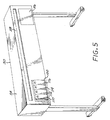
- FIG. 5 shows in isometric view an exemplary form of a large format printer/plotter in which the invention can be employed, wherein four off-carriage (or off-axis) ink containers 110, 112, 114, 116 are shown installed in an ink supply station.
- the printer/plotter of FIG. 5 further includes a housing 54, a front control panel 56 which provides user control switches, and a media output slot 58. While this exemplary printer/plotter is fed from a media roll, it should be appreciated that alternative sheet feed mechanisms can also be used.
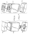
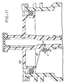
- FIGS. 6-14 schematically illustrated therein is a specific implementation of an ink container 200 which employs a low ink level sense apparatus that is comprised of a pressure transducer contained in the ink container, and which can be implemented as each of the ink containers 110-116 which are structurally substantially identical.
- the ink container 200 generally includes an outer container or pressure vessel 1102, a chassis member 1120 attached to a neck region 1102A at a leading end of the pressure vessel 1102, a leading end cap 1104 attached to the leading end of the pressure vessel, and a trailing end cap 1106 attached to the trailing end of the pressure vessel 1102.
- the ink container 200 further includes a collapsible ink bag or reservoir 114 disposed in an interior chamber 1103 defined by the pressure vessel 1102 and sealingly attached to a keel portion 1292 of the chassis 1120 which seals the interior of the pressure vessel 1102 from outside atmosphere while providing for an air inlet 1108 to the interior of the pressure vessel 1102, and an ink outlet port 1110 for ink contained in the ink reservoir 114.
- a collapsible ink bag or reservoir 114 disposed in an interior chamber 1103 defined by the pressure vessel 1102 and sealingly attached to a keel portion 1292 of the chassis 1120 which seals the interior of the pressure vessel 1102 from outside atmosphere while providing for an air inlet 1108 to the interior of the pressure vessel 1102, and an ink outlet port 1110 for ink contained in the ink reservoir 114.
- the chassis 1120 is secured to the opening of the neck region 1102A of the pressure vessel 1102, for example by an annular crimp ring 1280 that engages a top flange of the pressure vessel and an abutting flange of the chassis member.
- a pressure sealing O-ring 1152 suitably captured in a circumferential groove on the chassis 1120 engages the inside surface of the neck region 1102A of the pressure vessel 1102.
- the collapsible ink reservoir 114 more particularly comprises a pleated bag having opposing walls or sides 1114, 1116.
- an elongated sheet of bag material is folded such that opposed lateral edges of the sheet overlap or are brought together, forming an elongated cylinder.
- the lateral edges are sealed together, and pleats are in the resulting structure generally in alignment with the seal of the lateral edges.
- the bottom or non-feed end of the bag is formed by heat sealing the pleated structure along a seam transverse to the seal of the lateral edges.
- the top or feed end of the ink reservoir is formed similarly while leaving an opening for the bag to be sealingly attached to the keel portion 1292 of the chassis 1120.
- the ink reservoir bag is sealingly attached to keel portion 1292 by heat staking.
- the collapsible ink reservoir 114 thus defines an occupied portion 1103a of the interior chamber 1103, such that an unoccupied portion 1103b of the interior chamber 1103 is formed between the pressure vessel 1102 and the collapsible ink reservoir 114.
- the air inlet 1108 is the only flow path into or out of the unoccupied portion 1103b which functions as an air pressure chamber, and more particularly comprises a fluid conveying conduit that is in communication with the unoccupied portion 1103b of the interior chamber 1103.
- the ink outlet port 1110 is the only flow path into or out of the occupied portion 1103a and comprises a fluid conveying conduit that is in communication with the occupied portion 1103a of the interior chamber 1103, namely the interior of the collapsible ink reservoir 114.
- the ink outlet port 1110 is conveniently integrated with the keel portion 1292 of the chassis 1120.
- a pressure transducer 71 is disposed in the interior chamber 1103 so as to detect a difference between a pressure of the unoccupied portion 1103b of the interior chamber 1103 and a pressure of ink in the collapsible ink reservoir (i.e., a differential pressure), or a pressure of ink in the collapsible ink reservoir.
- the pressure transducer 71 is mounted on a ceramic substrate 73 to form a transducer subassembly that is attached to an outside wall of the output port 1110.
- a bore or opening in the wall of the output port 1110 and a bore or opening in the substrate 73 expose the pressure transducer to pressure in the output port 1110.
- Appropriate sealing including an O-ring 75 is provided to prevent leakage between the interior of the outlet port 1110 and the unoccupied portion 1103b of the interior chamber 1103.
- the electrical output of the pressure transducer 71 is provided to externally accessible contact pads 81 disposed on the top of the chassis 1120 via conductive leads 83 of a flexible printed circuit substrate 85 that extends between the ceramic substrate 73 and the top of the chassis 1120, passing on the outside surface of the chassis 1120 between the O-ring 1152 and such outside surface.
- the conductive leads 83 are electrically connected to the externally accessible contact pads 81 disposed on the top of the chassis which can be formed on one end of the flexible printed circuit substrate 85 that would be attached to the top of the chassis 1120.
- the output of the pressure transducer 71 can be sampled while printing which avoids the need to interrupt printing to take a reading.
- a memory chip package 87 can be conveniently mounted on the ceramic substrate 87 and interconnected to associated externally accessible contact pads by associated conductive leads 83 of the flexible printed circuit substrate 85.
- the pressure transducer 71 comprises a differential pressure transducer that is exposed to pressure in the ink outlet port 1110 and pressure in the unoccupied portion 1103b of the interior chamber 1103, and provides an output signal that is indicative of the difference between the air pressure in the unoccupied portion of the interior chamber 1103 and the pressure in the ink outlet port 1110.
- the pressure transducer 71 is very close to the ink supply in the collapsible ink reservoir 114 so as to avoid dynamic losses between the ink supply and the point of pressure measurement, and thus the pressure transducer 71 is effectively exposed to the ink supply pressure in the ink reservoir.
- the ink supply pressure in the ink reservoir 114 remains approximately equal to the pressure in the unoccupied portion 1103b of the interior chamber 1103 for much of the ink supply life, and thus the differential pressure is approximately zero for much of the ink supply life.
- pressure in the ink reservoir 114 begins to decrease with decreasing remaining ink, whereby the differential pressure increases with decreasing ink.
- the relationship between differential pressure and the amount of ink remaining is reasonably consistent for any given system and can be reliably characterized.
- differential pressure information is utilized to reliably determine a close to empty condition that is used to provide a warning to the user or to cease printing.
- the pressure transducer 71 comprises an absolute pressure transducer that is exposed only to the pressure in the collapsible ink reservoir, and provides an output signal that is indicative of the absolute pressure in the collapsible ink reservoir 114.
- An absolute pressure transducer can be employed for example wherein the pressure in the unoccupied portion 1103b is maintained at a known constant pressure, so that the output of the absolute pressure sensor can be compared with a constant pressure reference signal.
- the pressure transducer 71 comprises a pressure switch that provides an output when a sensed differential pressure exceeds a predetermined level, or when a sensed absolute pressure goes below a predetermined level. Such output can be utilized, for example, to generate a warning for the user that only a certain amount of ink is available for printing, or to cease printing.
- the invention can be employed in systems wherein the ink supply is subjected only to ambient or atmospheric pressure instead of a pressure that is greater than atmospheric pressure, for example in a system wherein a non-pressurized ink supply is elevated so that ink flows out of the ink container by gravity.
- the disclosed invention can be employed in other printing or marking systems that employ liquid ink such as liquid electrophotographic printing systems.
Landscapes
- Ink Jet (AREA)
Applications Claiming Priority (2)
| Application Number | Priority Date | Filing Date | Title |
|---|---|---|---|
| US698900 | 2000-10-27 | ||
| US09/698,900 US6435638B1 (en) | 2000-10-27 | 2000-10-27 | Ink bag fitment with an integrated pressure sensor for low ink detection |
Publications (2)
| Publication Number | Publication Date |
|---|---|
| EP1201437A1 true EP1201437A1 (de) | 2002-05-02 |
| EP1201437B1 EP1201437B1 (de) | 2005-02-02 |
Family
ID=24807118
Family Applications (1)
| Application Number | Title | Priority Date | Filing Date |
|---|---|---|---|
| EP01116837A Expired - Lifetime EP1201437B1 (de) | 2000-10-27 | 2001-07-10 | Tintensackanschlussverbindung mit integriertem Drucksensor zur Bestimmung von niedrigen Tintenpegeln |
Country Status (4)
| Country | Link |
|---|---|
| US (1) | US6435638B1 (de) |
| EP (1) | EP1201437B1 (de) |
| JP (1) | JP2002154219A (de) |
| DE (1) | DE60108701T2 (de) |
Cited By (8)
| Publication number | Priority date | Publication date | Assignee | Title |
|---|---|---|---|---|
| EP1494001A3 (de) * | 2003-04-24 | 2005-03-23 | Hewlett-Packard Development Company, L.P. | Kraftstoffzufuhrsystem |
| EP1808298A1 (de) * | 2006-01-16 | 2007-07-18 | Seiko Epson Corporation | Flüssigkeitsbehälter |
| EP1820653A3 (de) * | 2006-02-15 | 2008-07-09 | Seiko Epson Corporation | Flüssigkeitsbehälter |
| EP1820652A3 (de) * | 2006-02-15 | 2008-07-09 | Seiko Epson Corporation | Verfahren zur Erfassung einer Flüssigkeitsrestmenge, Fehlerdetektionsvorrichtung, Gerät mit Flüssigkeitsverbrauch und Flüssigkeitsbehälter |
| WO2020013840A1 (en) * | 2018-07-13 | 2020-01-16 | Hewlett-Packard Development Company, L.P. | Spouts with angled clamp flanges for a print liquid supply |
| US11198299B2 (en) | 2018-07-13 | 2021-12-14 | Hewlett-Packard Development Company, L.P. | Collar for fluid barrier |
| US11247477B2 (en) | 2018-07-13 | 2022-02-15 | Hewlett-Packard Development Company, L.P. | Coupling systems |
| US11390089B2 (en) | 2018-07-13 | 2022-07-19 | Hewlett-Packard Development Company, L.P. | Pliable print liquid supply reservoirs with offset spout |
Families Citing this family (37)
| Publication number | Priority date | Publication date | Assignee | Title |
|---|---|---|---|---|
| US6799820B1 (en) * | 1999-05-20 | 2004-10-05 | Seiko Epson Corporation | Liquid container having a liquid detecting device |
| US7225670B2 (en) * | 2000-05-18 | 2007-06-05 | Seiko Epson Corporation | Mounting structure, module, and liquid container |
| US7137679B2 (en) * | 2000-05-18 | 2006-11-21 | Seiko Epson Corporation | Ink consumption detecting method, and ink jet recording apparatus |
| EP1283110B1 (de) * | 2000-05-18 | 2009-03-04 | Seiko Epson Corporation | Verfahren zur detektion des tintenverbrauchs und tintenstrahlaufzeichnungsvorrichtung |
| EP1679196B1 (de) * | 2000-06-15 | 2008-05-07 | Seiko Epson Corporation | Verfahren zur Flüssigkeitszufuhr, Flüssigkeitsbehälter und Verfahren zu seiner Herstellung |
| CA2376135C (en) * | 2000-07-07 | 2005-09-27 | Seiko Epson Corporation | Liquid container, ink-jet recording apparatus, apparatus and method for controlling the same, apparatus and method for detecting liquid consumption state |
| EP1176403A3 (de) * | 2000-07-28 | 2003-03-19 | Seiko Epson Corporation | Flüssigkeitsverbrauchdetektor |
| JP2002273906A (ja) * | 2001-01-09 | 2002-09-25 | Seiko Epson Corp | インクジェット式記録装置および同装置におけるインク消費量演算機能の補正方法 |
| US6886929B2 (en) * | 2002-10-25 | 2005-05-03 | Hewlett-Packard Development Company, L.P. | Techniques for improving pressure sensor shock robustness in fluid containment devices |
| US7465040B2 (en) * | 2002-10-25 | 2008-12-16 | Hewlett-Packard Development Company, L.P. | Labyrinth seal structure with redundant fluid flow paths |
| US6827420B2 (en) * | 2002-12-18 | 2004-12-07 | Lexmark International, Inc. | Device verification using printed patterns and optical sensing |
| JP2004284094A (ja) * | 2003-03-20 | 2004-10-14 | Ricoh Co Ltd | インクカートリッジ及びインクジェット記録装置 |
| JP2004284093A (ja) * | 2003-03-20 | 2004-10-14 | Ricoh Co Ltd | インク袋保持部材、インクカートリッジ及びインクジェット記録装置 |
| JP2004276538A (ja) * | 2003-03-18 | 2004-10-07 | Ricoh Co Ltd | インク袋、インクカートリッジ及びインクジェット記録装置並びにインク充填方法、インク再充填方法、インクカートリッジの製造方法、インクカートリッジのリサイクル方法 |
| CA2461959C (en) * | 2003-03-26 | 2012-07-24 | Seiko Epson Corporation | Liquid container |
| JP2004306505A (ja) * | 2003-04-09 | 2004-11-04 | Brother Ind Ltd | インクパッケージ |
| JP4434032B2 (ja) * | 2005-02-16 | 2010-03-17 | セイコーエプソン株式会社 | 液滴吐出装置の制御方法、液滴吐出装置、電気光学装置の製造方法 |
| JP2006278270A (ja) * | 2005-03-30 | 2006-10-12 | Kyocera Corp | 燃料供給用カートリッジ及び燃料電池式携帯機器用置き台 |
| US7455395B2 (en) * | 2005-07-14 | 2008-11-25 | Hewlett-Packard Development Company, L.P. | Sensors |
| ATE532639T1 (de) * | 2005-09-07 | 2011-11-15 | Retail Inkjet Solutions | System und verfahren zum nachfüllen von tintenstrahlpatronen |
| JP2007216479A (ja) * | 2006-02-15 | 2007-08-30 | Seiko Epson Corp | 液体収容容器 |
| JP4877028B2 (ja) * | 2006-04-18 | 2012-02-15 | セイコーエプソン株式会社 | 液体収容容器 |
| JP2008030219A (ja) | 2006-07-26 | 2008-02-14 | Seiko Epson Corp | 液体噴射装置、液体収容体、及び液体収容体の液体残量判定方法 |
| JP5504630B2 (ja) * | 2008-03-25 | 2014-05-28 | セイコーエプソン株式会社 | 記録方法及び記録装置 |
| JP5099510B2 (ja) * | 2008-05-23 | 2012-12-19 | 株式会社セイコーアイ・インフォテック | インク袋アダプタ、アダプタ付きインク袋、及び印刷装置 |
| CN102294886B (zh) * | 2010-06-24 | 2013-09-11 | 研能科技股份有限公司 | 喷印系统 |
| US8573722B2 (en) | 2011-02-11 | 2013-11-05 | Infoprint Solutions Company, Llc | Ink flow regulation mechanism |
| JP2015198859A (ja) * | 2014-04-10 | 2015-11-12 | セイコーエプソン株式会社 | 流体噴射装置 |
| CN104742528B (zh) * | 2015-04-22 | 2016-09-07 | 京东方科技集团股份有限公司 | 一种打印设备 |
| CN108463703B (zh) * | 2015-10-28 | 2021-07-09 | 惠普发展公司,有限责任合伙企业 | 相对压力传感器 |
| US10753815B2 (en) | 2015-10-28 | 2020-08-25 | Hewlett-Packard Development Company, L.P. | Relative pressure sensor |
| CN110869215B (zh) | 2017-07-12 | 2021-09-03 | 惠普发展公司,有限责任合伙企业 | 确定喷墨打印机缺乏液体状态的方法和喷墨打印装置 |
| CN108730516A (zh) * | 2018-05-25 | 2018-11-02 | 南京佳乐净膜科技有限公司 | 墨水储存净化装置及墨水深度净化鲜化的方法 |
| CN112055658B (zh) | 2018-07-13 | 2022-06-21 | 惠普发展公司,有限责任合伙企业 | 用于打印液体供应源的具有楔形叉端的夹板 |
| EP3684621A1 (de) | 2018-08-01 | 2020-07-29 | Hewlett-Packard Development Company, L.P. | Kraftmesszellen für druckzuführungen |
| JP7342498B2 (ja) * | 2019-07-31 | 2023-09-12 | セイコーエプソン株式会社 | 収容体 |
| WO2022169458A1 (en) | 2021-02-05 | 2022-08-11 | Hewlett-Packard Development Company, L.P. | Printing fluid pressure determination |
Citations (5)
| Publication number | Priority date | Publication date | Assignee | Title |
|---|---|---|---|---|
| JPH0664184A (ja) * | 1993-03-18 | 1994-03-08 | Canon Inc | 液体残量検出装置及び液体吐出装置 |
| US5583545A (en) * | 1994-10-31 | 1996-12-10 | Hewlett-Packard Company | Ink level detection in a pressure regulated pen |
| US5992990A (en) * | 1996-10-24 | 1999-11-30 | Hewlett-Packard Company | Ink delivery system having an off-carriage pressure regulator |
| US6000773A (en) * | 1994-08-09 | 1999-12-14 | Encad, Inc. | Ink jet printer having ink use information stored in a memory mounted on a replaceable printer ink cartridge |
| EP0965451A2 (de) * | 1998-06-15 | 1999-12-22 | Canon Kabushiki Kaisha | Tintenstrahlaufzeichnungsvorrichtung und darin verwendeter Tintenbehälter |
Family Cites Families (17)
| Publication number | Priority date | Publication date | Assignee | Title |
|---|---|---|---|---|
| US4038650A (en) | 1975-10-14 | 1977-07-26 | Martin Evans | Fluid level detector and probe assembly |
| JPS5573564A (en) | 1978-11-29 | 1980-06-03 | Ricoh Co Ltd | Ink feed system of ink jet printer |
| US4544840A (en) | 1979-08-31 | 1985-10-01 | The Johns Hopkins University | Fiber optic fluid impurity detector |
| US4604633A (en) | 1982-12-08 | 1986-08-05 | Konishiroku Photo Industry Co., Ltd | Ink-jet recording apparatus |
| JPH0671791B2 (ja) | 1983-07-20 | 1994-09-14 | キヤノン株式会社 | インクジエツトプリンタのインク残量検知方法 |
| JPS6046256A (ja) | 1983-08-25 | 1985-03-13 | Canon Inc | 液体噴射記録装置 |
| US4639738A (en) | 1985-04-12 | 1987-01-27 | Eastman Kodak Company | Ink level detection system for ink jet printing apparatus |
| US5729256A (en) | 1987-04-15 | 1998-03-17 | Canon Kabushiki Kaisha | Ink remain detector having a biased flexible film member with limited deformation |
| EP0287098B1 (de) | 1987-04-15 | 1996-07-31 | Canon Kabushiki Kaisha | Detektor für übriggebliebene Tinte und Flüssigkeitseinspritzregistrierapparat mit diesem Detektor |
| JPH01237148A (ja) | 1988-03-18 | 1989-09-21 | Canon Inc | インクジェット記録装置 |
| EP0405555B1 (de) | 1989-06-29 | 1996-05-15 | Canon Kabushiki Kaisha | Verbesserte Tintenmengenfühlvorrichtung und Aufzeichnungsgerät mit der Vorrichtung |
| US4973993A (en) | 1989-07-11 | 1990-11-27 | Hewlett-Packard Company | Ink-quantity and low ink sensing for ink-jet printers |
| IT1256844B (it) | 1992-06-08 | 1995-12-21 | Olivetti & Co Spa | Metodo e dispositivo per il riconoscimento della fine-inchiostro in una testina di stampa a getto d'inchiostro. |
| JPH0664181A (ja) | 1992-08-18 | 1994-03-08 | Matsushita Electric Ind Co Ltd | インクジェットカートリッジ |
| SG47503A1 (en) | 1992-09-25 | 1998-04-17 | Hewlett Packard Co | Drop count-based ink-jet printer control method and apparatus |
| US6036296A (en) | 1996-10-31 | 2000-03-14 | Hewlett-Packard Company | Fluid level detection apparatus and method for determining the volume of fluid in a container |
| JPH11286121A (ja) * | 1998-02-06 | 1999-10-19 | Canon Inc | インクタンク、該インクタンクを用いるインクジェットプリントヘッド、プリントヘッドカ―トリッジおよびインクジェットプリント装置 |
-
2000
- 2000-10-27 US US09/698,900 patent/US6435638B1/en not_active Expired - Lifetime
-
2001
- 2001-07-10 DE DE60108701T patent/DE60108701T2/de not_active Expired - Lifetime
- 2001-07-10 EP EP01116837A patent/EP1201437B1/de not_active Expired - Lifetime
- 2001-10-23 JP JP2001324642A patent/JP2002154219A/ja active Pending
Patent Citations (5)
| Publication number | Priority date | Publication date | Assignee | Title |
|---|---|---|---|---|
| JPH0664184A (ja) * | 1993-03-18 | 1994-03-08 | Canon Inc | 液体残量検出装置及び液体吐出装置 |
| US6000773A (en) * | 1994-08-09 | 1999-12-14 | Encad, Inc. | Ink jet printer having ink use information stored in a memory mounted on a replaceable printer ink cartridge |
| US5583545A (en) * | 1994-10-31 | 1996-12-10 | Hewlett-Packard Company | Ink level detection in a pressure regulated pen |
| US5992990A (en) * | 1996-10-24 | 1999-11-30 | Hewlett-Packard Company | Ink delivery system having an off-carriage pressure regulator |
| EP0965451A2 (de) * | 1998-06-15 | 1999-12-22 | Canon Kabushiki Kaisha | Tintenstrahlaufzeichnungsvorrichtung und darin verwendeter Tintenbehälter |
Non-Patent Citations (1)
| Title |
|---|
| PATENT ABSTRACTS OF JAPAN vol. 018, no. 304 (M - 1619) 10 June 1994 (1994-06-10) * |
Cited By (14)
| Publication number | Priority date | Publication date | Assignee | Title |
|---|---|---|---|---|
| EP1494001A3 (de) * | 2003-04-24 | 2005-03-23 | Hewlett-Packard Development Company, L.P. | Kraftstoffzufuhrsystem |
| US7788048B2 (en) | 2003-04-24 | 2010-08-31 | Hewlett-Packard Development Company, L.P. | Apparatus and method for integrating a fuel supply and a fuel level sensing pressure sensor |
| KR101091262B1 (ko) * | 2003-04-24 | 2011-12-07 | 에버레디 배터리 컴퍼니, 인크. | 연료 공급 장치, 연료 게이지, 압력 센서, 연료 전지시스템, 전자 장치, 연료 카트리지 제조 방법 및 연료레벨 검출 방법 |
| EP1808298A1 (de) * | 2006-01-16 | 2007-07-18 | Seiko Epson Corporation | Flüssigkeitsbehälter |
| EP1820653A3 (de) * | 2006-02-15 | 2008-07-09 | Seiko Epson Corporation | Flüssigkeitsbehälter |
| EP1820652A3 (de) * | 2006-02-15 | 2008-07-09 | Seiko Epson Corporation | Verfahren zur Erfassung einer Flüssigkeitsrestmenge, Fehlerdetektionsvorrichtung, Gerät mit Flüssigkeitsverbrauch und Flüssigkeitsbehälter |
| WO2020013840A1 (en) * | 2018-07-13 | 2020-01-16 | Hewlett-Packard Development Company, L.P. | Spouts with angled clamp flanges for a print liquid supply |
| CN112423988A (zh) * | 2018-07-13 | 2021-02-26 | 惠普发展公司,有限责任合伙企业 | 用于打印液体供给装置的具有倾斜夹紧凸缘的管嘴 |
| US11186093B2 (en) | 2018-07-13 | 2021-11-30 | Hewlett-Packard Development Company, L.P. | Spouts with angled clamp flanges for a print liquid supply |
| US11198299B2 (en) | 2018-07-13 | 2021-12-14 | Hewlett-Packard Development Company, L.P. | Collar for fluid barrier |
| US11247477B2 (en) | 2018-07-13 | 2022-02-15 | Hewlett-Packard Development Company, L.P. | Coupling systems |
| US11390089B2 (en) | 2018-07-13 | 2022-07-19 | Hewlett-Packard Development Company, L.P. | Pliable print liquid supply reservoirs with offset spout |
| EP4129699A1 (de) * | 2018-07-13 | 2023-02-08 | Hewlett-Packard Development Company L.P. | Tüllen mit abgewinkelten klemmflanschen für eine druckflüssigkeitszufuhr |
| US11807016B2 (en) | 2018-07-13 | 2023-11-07 | Hewlett-Packard Development Company, L.P. | Pliable print liquid supply reservoirs with offset spout |
Also Published As
| Publication number | Publication date |
|---|---|
| US6435638B1 (en) | 2002-08-20 |
| DE60108701T2 (de) | 2006-01-12 |
| EP1201437B1 (de) | 2005-02-02 |
| JP2002154219A (ja) | 2002-05-28 |
| DE60108701D1 (de) | 2005-03-10 |
Similar Documents
| Publication | Publication Date | Title |
|---|---|---|
| US6435638B1 (en) | Ink bag fitment with an integrated pressure sensor for low ink detection | |
| US6988793B2 (en) | Collapsible ink reservoir with a collapse resisting insert | |
| US6164743A (en) | Ink container with an inductive ink level sense | |
| EP0882595B1 (de) | Tintenfüllstandsschätzung mittels Tropfenzählung und Tintenfüllstandsbestimmung | |
| EP1413443B1 (de) | Vor Erschütterungen geschützter Drucksensor in Flüssigkeitsbehältnis | |
| EP0941854B1 (de) | Kostengünstiger, unter Druck setzbarer Tintenbehälter | |
| EP0986483B1 (de) | Tintenbehälter mit mehrfunktionsrahmen | |
| JP3766135B2 (ja) | インクジェットプリンタ・プロッタ | |
| KR20010013318A (ko) | 잉크 용기 및 잉크 용기를 잉크젯 인쇄 시스템내에설치하기 위한 조립 방법 | |
| JP2009073096A (ja) | 液体収容容器および液体噴射装置 | |
| JPH07125236A (ja) | インクカートリッジ | |
| US7465040B2 (en) | Labyrinth seal structure with redundant fluid flow paths | |
| JPH0615843A (ja) | インクカートリッジならびにそれを具えた記録装置 | |
| US20250162325A1 (en) | Liquid supply apparatus | |
| AU693894B2 (en) | Valve, liquid container using same, recording heat cartridge having liquid container and recording apparatus using liquid container |
Legal Events
| Date | Code | Title | Description |
|---|---|---|---|
| PUAI | Public reference made under article 153(3) epc to a published international application that has entered the european phase |
Free format text: ORIGINAL CODE: 0009012 |
|
| AK | Designated contracting states |
Kind code of ref document: A1 Designated state(s): AT BE CH CY DE DK ES FI FR GB GR IE IT LI LU MC NL PT SE TR Kind code of ref document: A1 Designated state(s): DE FR GB NL |
|
| AX | Request for extension of the european patent |
Free format text: AL;LT;LV;MK;RO;SI |
|
| 17P | Request for examination filed |
Effective date: 20020705 |
|
| AKX | Designation fees paid |
Free format text: DE FR GB NL |
|
| 17Q | First examination report despatched |
Effective date: 20040217 |
|
| GRAP | Despatch of communication of intention to grant a patent |
Free format text: ORIGINAL CODE: EPIDOSNIGR1 |
|
| GRAS | Grant fee paid |
Free format text: ORIGINAL CODE: EPIDOSNIGR3 |
|
| GRAA | (expected) grant |
Free format text: ORIGINAL CODE: 0009210 |
|
| AK | Designated contracting states |
Kind code of ref document: B1 Designated state(s): DE FR GB NL |
|
| REG | Reference to a national code |
Ref country code: GB Ref legal event code: FG4D |
|
| REG | Reference to a national code |
Ref country code: IE Ref legal event code: FG4D |
|
| REF | Corresponds to: |
Ref document number: 60108701 Country of ref document: DE Date of ref document: 20050310 Kind code of ref document: P |
|
| PLBE | No opposition filed within time limit |
Free format text: ORIGINAL CODE: 0009261 |
|
| STAA | Information on the status of an ep patent application or granted ep patent |
Free format text: STATUS: NO OPPOSITION FILED WITHIN TIME LIMIT |
|
| ET | Fr: translation filed | ||
| 26N | No opposition filed |
Effective date: 20051103 |
|
| REG | Reference to a national code |
Ref country code: GB Ref legal event code: 732E Free format text: REGISTERED BETWEEN 20120329 AND 20120404 |
|
| REG | Reference to a national code |
Ref country code: NL Ref legal event code: SD Effective date: 20120731 |
|
| REG | Reference to a national code |
Ref country code: FR Ref legal event code: PLFP Year of fee payment: 16 |
|
| REG | Reference to a national code |
Ref country code: FR Ref legal event code: PLFP Year of fee payment: 17 |
|
| PGFP | Annual fee paid to national office [announced via postgrant information from national office to epo] |
Ref country code: FR Payment date: 20170621 Year of fee payment: 17 Ref country code: GB Payment date: 20170620 Year of fee payment: 17 |
|
| PGFP | Annual fee paid to national office [announced via postgrant information from national office to epo] |
Ref country code: NL Payment date: 20170622 Year of fee payment: 17 |
|
| PGFP | Annual fee paid to national office [announced via postgrant information from national office to epo] |
Ref country code: DE Payment date: 20170620 Year of fee payment: 17 |
|
| REG | Reference to a national code |
Ref country code: DE Ref legal event code: R119 Ref document number: 60108701 Country of ref document: DE |
|
| REG | Reference to a national code |
Ref country code: NL Ref legal event code: MM Effective date: 20180801 |
|
| GBPC | Gb: european patent ceased through non-payment of renewal fee |
Effective date: 20180710 |
|
| PG25 | Lapsed in a contracting state [announced via postgrant information from national office to epo] |
Ref country code: GB Free format text: LAPSE BECAUSE OF NON-PAYMENT OF DUE FEES Effective date: 20180710 Ref country code: FR Free format text: LAPSE BECAUSE OF NON-PAYMENT OF DUE FEES Effective date: 20180731 Ref country code: DE Free format text: LAPSE BECAUSE OF NON-PAYMENT OF DUE FEES Effective date: 20190201 |
|
| PG25 | Lapsed in a contracting state [announced via postgrant information from national office to epo] |
Ref country code: NL Free format text: LAPSE BECAUSE OF NON-PAYMENT OF DUE FEES Effective date: 20180801 |