EP1201577B1 - Einrichtung zum Zuführen von Bogen - Google Patents
Einrichtung zum Zuführen von Bogen Download PDFInfo
- Publication number
- EP1201577B1 EP1201577B1 EP01122532A EP01122532A EP1201577B1 EP 1201577 B1 EP1201577 B1 EP 1201577B1 EP 01122532 A EP01122532 A EP 01122532A EP 01122532 A EP01122532 A EP 01122532A EP 1201577 B1 EP1201577 B1 EP 1201577B1
- Authority
- EP
- European Patent Office
- Prior art keywords
- drive
- speed
- sheets
- transport
- sheet
- Prior art date
- Legal status (The legal status is an assumption and is not a legal conclusion. Google has not performed a legal analysis and makes no representation as to the accuracy of the status listed.)
- Expired - Lifetime
Links
- 230000005540 biological transmission Effects 0.000 claims description 19
- 241000252254 Catostomidae Species 0.000 claims description 14
- 230000033001 locomotion Effects 0.000 claims description 8
- 230000008878 coupling Effects 0.000 claims description 2
- 238000010168 coupling process Methods 0.000 claims description 2
- 238000005859 coupling reaction Methods 0.000 claims description 2
- 230000001105 regulatory effect Effects 0.000 claims 3
- 230000006978 adaptation Effects 0.000 claims 1
- 125000004122 cyclic group Chemical group 0.000 claims 1
- 238000000926 separation method Methods 0.000 claims 1
- 238000010586 diagram Methods 0.000 description 4
- 238000005457 optimization Methods 0.000 description 2
- 230000001133 acceleration Effects 0.000 description 1
- 238000006073 displacement reaction Methods 0.000 description 1
- 239000002184 metal Substances 0.000 description 1
Images


Classifications
-
- B—PERFORMING OPERATIONS; TRANSPORTING
- B65—CONVEYING; PACKING; STORING; HANDLING THIN OR FILAMENTARY MATERIAL
- B65H—HANDLING THIN OR FILAMENTARY MATERIAL, e.g. SHEETS, WEBS, CABLES
- B65H11/00—Feed tables
- B65H11/002—Feed tables incorporating transport belts
-
- B—PERFORMING OPERATIONS; TRANSPORTING
- B65—CONVEYING; PACKING; STORING; HANDLING THIN OR FILAMENTARY MATERIAL
- B65H—HANDLING THIN OR FILAMENTARY MATERIAL, e.g. SHEETS, WEBS, CABLES
- B65H29/00—Delivering or advancing articles from machines; Advancing articles to or into piles
- B65H29/66—Advancing articles in overlapping streams
- B65H29/6609—Advancing articles in overlapping streams forming an overlapping stream
-
- B—PERFORMING OPERATIONS; TRANSPORTING
- B65—CONVEYING; PACKING; STORING; HANDLING THIN OR FILAMENTARY MATERIAL
- B65H—HANDLING THIN OR FILAMENTARY MATERIAL, e.g. SHEETS, WEBS, CABLES
- B65H29/00—Delivering or advancing articles from machines; Advancing articles to or into piles
- B65H29/66—Advancing articles in overlapping streams
- B65H29/6654—Advancing articles in overlapping streams changing the overlapping figure
-
- B—PERFORMING OPERATIONS; TRANSPORTING
- B65—CONVEYING; PACKING; STORING; HANDLING THIN OR FILAMENTARY MATERIAL
- B65H—HANDLING THIN OR FILAMENTARY MATERIAL, e.g. SHEETS, WEBS, CABLES
- B65H3/00—Separating articles from piles
- B65H3/08—Separating articles from piles using pneumatic force
- B65H3/0808—Suction grippers
- B65H3/0816—Suction grippers separating from the top of pile
-
- B—PERFORMING OPERATIONS; TRANSPORTING
- B65—CONVEYING; PACKING; STORING; HANDLING THIN OR FILAMENTARY MATERIAL
- B65H—HANDLING THIN OR FILAMENTARY MATERIAL, e.g. SHEETS, WEBS, CABLES
- B65H5/00—Feeding articles separated from piles; Feeding articles to machines
- B65H5/24—Feeding articles in overlapping streams, i.e. by separation of articles from a pile
-
- B—PERFORMING OPERATIONS; TRANSPORTING
- B65—CONVEYING; PACKING; STORING; HANDLING THIN OR FILAMENTARY MATERIAL
- B65H—HANDLING THIN OR FILAMENTARY MATERIAL, e.g. SHEETS, WEBS, CABLES
- B65H5/00—Feeding articles separated from piles; Feeding articles to machines
- B65H5/34—Varying the phase of feed relative to the receiving machine
-
- B—PERFORMING OPERATIONS; TRANSPORTING
- B65—CONVEYING; PACKING; STORING; HANDLING THIN OR FILAMENTARY MATERIAL
- B65H—HANDLING THIN OR FILAMENTARY MATERIAL, e.g. SHEETS, WEBS, CABLES
- B65H2301/00—Handling processes for sheets or webs
- B65H2301/10—Selective handling processes
- B65H2301/14—Selective handling processes of batches of material of different characteristics
- B65H2301/141—Selective handling processes of batches of material of different characteristics of different format, e.g. A0 - A4
-
- B—PERFORMING OPERATIONS; TRANSPORTING
- B65—CONVEYING; PACKING; STORING; HANDLING THIN OR FILAMENTARY MATERIAL
- B65H—HANDLING THIN OR FILAMENTARY MATERIAL, e.g. SHEETS, WEBS, CABLES
- B65H2301/00—Handling processes for sheets or webs
- B65H2301/40—Type of handling process
- B65H2301/44—Moving, forwarding, guiding material
- B65H2301/443—Moving, forwarding, guiding material by acting on surface of handled material
- B65H2301/4432—Moving, forwarding, guiding material by acting on surface of handled material by means having an operating surface contacting only one face of the material, e.g. roller
- B65H2301/44322—Moving, forwarding, guiding material by acting on surface of handled material by means having an operating surface contacting only one face of the material, e.g. roller belt
-
- B—PERFORMING OPERATIONS; TRANSPORTING
- B65—CONVEYING; PACKING; STORING; HANDLING THIN OR FILAMENTARY MATERIAL
- B65H—HANDLING THIN OR FILAMENTARY MATERIAL, e.g. SHEETS, WEBS, CABLES
- B65H2403/00—Power transmission; Driving means
- B65H2403/80—Transmissions, i.e. for changing speed
- B65H2403/82—Variable speed drive units
-
- B—PERFORMING OPERATIONS; TRANSPORTING
- B65—CONVEYING; PACKING; STORING; HANDLING THIN OR FILAMENTARY MATERIAL
- B65H—HANDLING THIN OR FILAMENTARY MATERIAL, e.g. SHEETS, WEBS, CABLES
- B65H2511/00—Dimensions; Position; Numbers; Identification; Occurrences
- B65H2511/20—Location in space
- B65H2511/22—Distance
-
- B—PERFORMING OPERATIONS; TRANSPORTING
- B65—CONVEYING; PACKING; STORING; HANDLING THIN OR FILAMENTARY MATERIAL
- B65H—HANDLING THIN OR FILAMENTARY MATERIAL, e.g. SHEETS, WEBS, CABLES
- B65H2513/00—Dynamic entities; Timing aspects
- B65H2513/10—Speed
-
- B—PERFORMING OPERATIONS; TRANSPORTING
- B65—CONVEYING; PACKING; STORING; HANDLING THIN OR FILAMENTARY MATERIAL
- B65H—HANDLING THIN OR FILAMENTARY MATERIAL, e.g. SHEETS, WEBS, CABLES
- B65H2601/00—Problem to be solved or advantage achieved
- B65H2601/40—Increasing or maximizing
- B65H2601/42—Increasing or maximizing entities relating to the handling machine
- B65H2601/422—Versatility
-
- B—PERFORMING OPERATIONS; TRANSPORTING
- B65—CONVEYING; PACKING; STORING; HANDLING THIN OR FILAMENTARY MATERIAL
- B65H—HANDLING THIN OR FILAMENTARY MATERIAL, e.g. SHEETS, WEBS, CABLES
- B65H2701/00—Handled material; Storage means
- B65H2701/10—Handled articles or webs
- B65H2701/17—Nature of material
- B65H2701/176—Cardboard
Definitions
- the invention relates to a device for supplying sheets to a suction head to Cyclically separating the sheets from a stack of separating suction cups, with transport suckers for transporting the sheets in the sheet conveying direction to a belt table, having the conveyor belts, transported by the bow in a scale and subsequently fed to a sheet-processing machine, with a drive for the Suction head and a drive for the conveyor belts, which influences the conveying speed and thus the relay spacing of the bow is switchable.
- the disadvantage is that only at a speed and thus a stagger spacing an optimization of the acceleration and speed curves of the conveyor belts and transport suction and thus an optimization of the transfer conditions between the conveyor belts and the transport suckers is possible. This results in a different speed and so changed season distance to early, late or oblique. Since the sheets to be processed can be made of cardboard, plastic, sheet metal or paper, there is also the possibility that paper sheets are damaged during the transfer or when processing rigid sheets, the transport suckers are subject to high wear.
- the object of the invention is to change a generic device so that at every staggering distance optimal conditions when transferring the sheets from the transport suckers can be realized on the conveyor belts.
- the object is achieved by the features of claim 1.
- the solution according to the invention it is possible to increase the universality of sheet-processing machines by the staggering distance can be changed, the transfer conditions remain constant regardless of the respective stagger spacing.
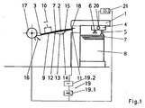
- the apparatus shown in Fig. 1 for feeding sheets consists of a sheet feeder 1, a belt table 2 and the belt table 2 associated front marks 3.
- the sheet feeder 1 has a suction head 4 with suction pads 5 and 6 transport suction.
- an existing sheet of sheet pile 8 8 is provided in sheet feeder 1 .
- the belt conveyor 2 downstream of the sheet feeder 1 in the sheet conveying direction 10 has a table sheet 9 and belt rollers 11, 12 extending transversely to the sheet conveying direction 10.
- the band rollers 11, 12 are wrapped by one or more conveyor belts 13, which are guided by guide rollers 14 and tension rollers 15.
- the front markers 3 provided on the end of the belt table 2 facing away from the sheet feeder 1 can be moved periodically from the position shown in FIG. 1 into a position below the belt table 2 by means not shown.
- the belt table 2, a vibrating system 16 and a feed drum 17 are further downstream of a sheet-processing machine and in the region of the sheet feeder 1 facing end associated with a belt roller 11 clock roller 18.
- One of the belt rollers 11, 12 is a drive 19, assigned in the embodiment of the belt roller 11.
- the drive 19 consists of a transmission gear 19.1 and a manual transmission 19.2.
- the gearbox 19.2 derived from the downstream sheet-processing machine uniform rotary motion is fed to the transmission gear 19.1, which converts them into a sinusoidal rotational movement.
- the transmission gear 19.1 is coupled to the belt roller 11.
- the manual transmission 19.2 for example, provided with switch positions I, II, III, with other switching positions can be provided.
- switch positions I, II, III with other switching positions can be provided.
- a translation 1: 1 In the switching position I, a translation 1: 1 and thus, for example, such a graduated spacing realized that n sheet 7 lie on the belt table 2.
- an electric motor 22 as the drive 19 and to assign the suction head 4 as the drive 20 to an electric motor 23.
- the motors 22, 23 and thus the conveyor belts 13 and the suction head 4 via a computer and control unit 24 is clocked synchronously with the sheet-processing machine driven by the computer and control unit 24 synchronizing signals of the sheet processing machine are fed to a such a pitch is realized that n sheets 7 lie on the belt table 2 and the transfer conditions are optimized.
- a sinusoidal drive of the conveyor belts 13 is also realized in a likewise known manner.
- an input device 25 for example, in order to be able to change the graduation distance 1, eg a transmission ratio n +1 or n-1 is activated, whereby n + 1 sheet 7 or n-1 sheet 7 are provided on the belt table 2.
- the control and control device 24 is further associated with a memory 26 by speed profiles are stored, which the motor 23 of the suction head 4 follows and thus the transport suction 6 drives so that when changing the stagger spacing 1 optimal transfer conditions in the transfer of the sheet 7 of the transport suckers 6 are given to the conveyor belts 13.
Landscapes
- Engineering & Computer Science (AREA)
- Mechanical Engineering (AREA)
- Sheets, Magazines, And Separation Thereof (AREA)
- Delivering By Means Of Belts And Rollers (AREA)
Description
Um die Schuppung zu verändern, ist es aus der EP 0 313 868 A2 bekannt, den Transportbändern einen Antrieb zuzuordnen, mit dem unterschiedliche Transportgeschwindigkeiten realisiert werden können. So können bei einer ersten Geschwindigkeit großformatige Bogen schuppenförmig und bei einer zweiten Geschwindigkeit, die doppelt so groß wie die erste Geschwindigkeit ist, kleinformatige Bogen als Einzelbogen angelegt werden.
Damit kommt es bei einer anderen Geschwindigkeit und so geändertem Staffelabstand zu Früh-, Spät- oder Schiefbogen. Da die zur Verarbeitung gelangenden Bogen aus Karton, Kunststoff, Blech oder Papier bestehen können, besteht außerdem die Möglichkeit, dass Papierbogen bei der Übergabe beschädigt werden bzw. bei der Verarbeitung steifer Bogen die Transportsauger einem hohen Verschleiß unterliegen.
Durch die erfindungsgemäße Lösung ist es möglich, die Universalität von bogenverarbeitenden Maschinen zu erhöhen, indem der Staffelabstand verändert werden kann, wobei die Übergabebedingungen unabhängig vom jeweiligen Staffelabstand konstant bleiben.
- Fig. 1:
- eine Einrichtung zum Zuführen von Bogen in der Seitenansicht
- Fig. 2:
- das Wegschaubild der Transportbänder
- Fig. 3:
- das Geschwindigkeitsschaubild der Transportbänder
- Fig. 4:
- das Wegschaubild der Transportsauger
- Fig. 5:
- das Geschwindigkeitsschaubild der Transportsauger
- Fig. 6:
- den Überlagerungsgeschwindigkeitsverlauf des Antriebs für den Saugkopf
- Fig. 7:
- den Drehzahlverlauf des Antriebs für den Saugkopf
- Fig. 8:
- eine weitere Ausführungsform der Einrichtung gem. Fig. 1.
Die am dem Bogenanleger 1 abgewandten Ende des Bändertischs 2 vorgesehenen Vordermarken 3 können durch nicht dargestellte Mittel periodisch aus der in Fig. 1 dargestellten Position in eine Position unter dem Bändertisch 2 verbracht werden. Dem Bändertisch 2 sind weiterhin eine Schwinganlage 16 und eine Anlegtrommel 17 einer bogenverarbeitenden Maschine nachgeordnet sowie im Bereich des dem Bogenanleger 1 zugewandten Endes eine mit der Bänderwalze 11 korrespondierende Taktwalze 18 zugeordnet.
Einer der Bänderwalzen 11, 12 ist ein Antrieb 19, im Ausführungsbeispiel der Bänderwalze 11, zugeordnet. Der Antrieb 19 besteht aus einem Übertragungsgetriebe 19.1 und einem Schaltgetriebe 19.2.
Zur Vermeidung dieser Nachteile ist einem dem Saugkopf 4 zugeordnetem Antrieb 20 ein eine sinusähnliche Abtriebsbewegung realisierendes Getriebe 21 vorgeordnet. Dieses Getriebe 21 kann z.B. als Räderkoppelgetriebe ausgebildet sein und weist analog zum Schaltgetriebe 19.2 ebenfalls drei Schaltstellung I, II, III auf. Ist das Schaltgetriebe 19.2 mit weiteren Schaltstufen versehen, so ist auch das Getriebe 21 mit einer entsprechenden Anzahl Schaltstufen ausgestattet. In der Schaltstellung I wird die von der dem Bogenanleger 1 nachgeordneten bogenverarbeitenden Maschine abgeleitete gleichförmige Drehbewegung ohne Überlagerung mit einer anderen Bewegung dem Antrieb 20 des Saugkopfes 4 zugeführt. Ist auch die Schaltstellung I des Übertragungsgetriebes 19.1 eingestellt, werden ein für den Bogenanleger 1 charakteristischer Staffelabstand und damit n Bogen 7 auf dem Bändertisch 2 sowie optimale Übergabebedingungen bei der Übergabe der Bogen 7 von den Transportsaugern 6 an die Transportbänder 13 realisiert.
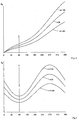
In diesem Übergabepunkt Ü sind die Geschwindigkeitsverhältnisse zwischen den Transportsaugern 6 und den Transportbändern 12 aufeinander abgestimmt und damit die Übergabebedingungen optimiert. Da, wie aus den Fig. 2 und 3 ersichtlich, in den Schaltstellungen II und III des Schaltgetriebes 19.2 im Übergabepunkt Ü die Weg- und Geschwindigkeitsverläufe verändert wurden, müssen die Weg- und Geschwindigkeitsverläufe der Transportsauger 6 entsprechend nachgeführt werden, was, wie in den Figuren 4 und 5 dargestellt, durch Überlagerung des Geschwindigkeitsverlaufes VA bei n Bogen 7 mit der von dem Getriebe 21 initiierten Sinusbewegung (Fig. 6) realisiert wird. In der Figur 7 ist der Verlauf der Drehzahl WA des Antriebes 20 dargestellt und gezeigt, dass die momentane Drehzahl im Übergabepunkt Ü unabhängig von der gewählten Schaltstellung I, II oder III gleich ist.
Das Schaltgetriebe 19.2 und das eine sinusähnliche Abtriebsbewegung realisierende Getriebe 21 können verknüpft sein, so dass bei einer Stellhandlung jeweils für beide Getriebe 19.2, 21 gleiche Schaltstufen eingestellt werden.
Unabhängig davon ist es auch möglich, als Antrieb 19 einen Elektromotor 22 vorzusehen und dem Saugkopf 4 als Antrieb 20 einen Elektromotor 23 zuzuordnen. In an sich bekannter Weise werden die Motoren 22, 23 und damit die Transportbänder 13 und der Saugkopf 4 über eine Rechner- und Steuereinheit 24 taktsynchron mit der bogenverarbeitenden Maschine angetrieben, indem der Rechner- und Steuereinheit 24 Synchronisiersignale der bogenverarbeitenden Maschine zugeleitet werden, wobei ein solcher Staffelabstand realisiert wird, dass n Bogen 7 auf dem Bändertisch 2 liegen und die Übergabebedingungen optimiert sind. Durch die Rechner- und Steuereinheit 24 wird weiterhin auf ebenfalls bekannte Weise ein sinusförmiger Antrieb der Transportbänder 13 realisiert. Über ein Eingabegerät 25 kann au-βerdem, um den Staffelabstand 1 verändern zu können, z.B. ein Übersetzungsverhältnis n +1 oder n - 1 aktiviert werden, wodurch n + 1 Bogen 7 oder n - 1 Bogen 7 auf dem Bändertisch 2 vorgesehen werden. Der Regel- und Steuereinrichtung 24 ist weiterhin ein Speicher 26 zugeordnet, indem Geschwindigkeitsverläufe abgelegt sind, denen der Motor 23 des Saugkopfes 4 folgt und damit die Transportsauger 6 so antreibt, dass bei einer Änderung des Staffelabstandes 1 optimale Übergabebedingungen bei der Übergabe der Bogen 7 von den Transportsaugern 6 an die Transportbänder 13 gegeben sind.
- 1
- Bogenanleger
- 2
- Bändertisch
- 3
- Vordermarke
- 4
- Saugkopf
- 5
- Trennsauger
- 6
- Transportsauger
- 7
- Bogen
- 8
- Bogenstapel
- 9
- Tischblech
- 10
- Bogenförderrichtung
- 11
- Bänderwalze
- 12
- Bänderwalze
- 13
- Transportband
- 14
- Umlenkrolle
- 15
- Spannrolle
- 16
- Schwinganlage
- 17
- Anlegtrommel
- 18
- Taktwalze
- 19
- Antrieb
- 19.1
- Übertragungsgetriebe
- 19.2
- Schaltgetriebe
- 20
- Antrieb
- 21
- Getriebe
- 22
- erster Elektromotor
- 23
- zweiter Elektromotor
- 24
- Rechner- und Steuereinheit
- 25
- Eingabegerät
- 26
- Speicher
- I
- Schaltstellung
- II
- Schaltstellung
- III
- Schaltstellung
- n
- Anzahl von Bogen 7 auf dem Bändertisch 2
- SB
- Weg der Transportbänder 13
- ST
- Weg der Transportsauger 6
- VB
- Geschwindigkeit der Transportbänder 13
- VT
- Geschwindigkeit der Transportsauger 6
- VA
- Überlagerungsgeschwindigkeit
- WA
- Drehzahl des Antriebes 20
- Ü
- Übergabepunkt
- 1
- Staffelabstand
Claims (6)
- Einrichtung zum Zuführen von Bogen (7) mit an einem Saugkopf (4) zum taktweisen Vereinzeln der Bogen (7) von einem Stapel (8) angeordneten Trennsaugern (5), mit Transportsaugern (6) zum Transportieren der Bogen (7) in Bogenförderrichtung (10) zu einem Bändertisch (2), der Transportbänder (13) aufweist, durch die die Bogen (7) schuppenförmig transportiert und nachfolgend einer bogenverarbeitenden Maschine zugeführt werden, mit einem Antrieb (20) für den Saugkopf (4) sowie einen Antrieb (19) für die Transportbänder (13), der zur Beeinflussung der Geschwindigkeit der Transportbänder (13) und damit des Staffelabstandes (I) der Bogen (7) umschaltbar ist, dadurch gekennzeichnet, dass zum Nachführen der Geschwindigkeit (VT) der Transportsauger (6) der jeweils gewählten Geschwindigkeit (VB) der Transportbänder (13) der Antrieb (20) des Saugkopfes (4) mit einer sinusähnlichen Überlagerungsgeschwindigkeit (VA) überlagerbar ist.
- Einrichtung nach Anspruch 1, dadurch gekennzeichnet, dass dem Antrieb (20) ein eine sinusähnliche Abtriebsbewegung realisierendes Getriebe (21) zugeordnet ist.
- Einrichtung nach Anspruch 1 und 2, dadurch gekennzeichnet, dass das Getriebe (21) als Räderkoppelgetriebe ausgebildet ist.
- Einrichtung nach Anspruch 1 bis 3, dadurch gekennzeichnet, dass dem Antrieb (19) der Transportbänder (13) ein Schaltgetriebe (19.2) zugeordnet ist, das mit dem Getriebe (21) in Wirkverbindung steht.
- Einrichtung nach Anspruch 1, dadurch gekennzeichnet, dass ein erster Elektromotor (22) als Antrieb (19) für die Transportbänder (13) und ein zweiter Elektromotor (23) als Antrieb (20) für den Saugkopf (4) vorgesehen ist, die über eine Regel- und Steuereinheit (24) taktsynchron mit der bogenverarbeitenden Maschine antreibbar sind, wobei zur Veränderung des Staffelabstandes (1) die Geschwindigkeit des Antriebes (19) mittels eines der Regel- und Steuereinheit (24) zugeordneten Eingabegerätes (25) einstellbar ausgeführt ist.
- Einrichtung nach Anspruch 1 bis 5, dadurch gekennzeichnet, dass in einem der Regel- und Steuereinheit (24) zugeordneten Speicher (26) Geschwindigkeitsverläufe abgelegt sind, mit denen ein Ansteuern des zweiten Elektromotors (23) zur Anpassung der Geschwindigkeitsverhältnisse bei der Übergabe der Bogen (7) von den Transportsaugern (6) an die Transportbänder (13) bei unterschiedlichen Staffelabständen (1) erfolgt.
Applications Claiming Priority (2)
| Application Number | Priority Date | Filing Date | Title |
|---|---|---|---|
| DE10052772A DE10052772A1 (de) | 2000-10-25 | 2000-10-25 | Einrichtung zum Zuführen von Bogen |
| DE10052772 | 2000-10-25 |
Publications (3)
| Publication Number | Publication Date |
|---|---|
| EP1201577A2 EP1201577A2 (de) | 2002-05-02 |
| EP1201577A3 EP1201577A3 (de) | 2004-01-28 |
| EP1201577B1 true EP1201577B1 (de) | 2005-12-07 |
Family
ID=7660937
Family Applications (1)
| Application Number | Title | Priority Date | Filing Date |
|---|---|---|---|
| EP01122532A Expired - Lifetime EP1201577B1 (de) | 2000-10-25 | 2001-09-24 | Einrichtung zum Zuführen von Bogen |
Country Status (2)
| Country | Link |
|---|---|
| EP (1) | EP1201577B1 (de) |
| DE (2) | DE10052772A1 (de) |
Cited By (1)
| Publication number | Priority date | Publication date | Assignee | Title |
|---|---|---|---|---|
| DE102008013101A1 (de) | 2007-03-23 | 2008-09-25 | Heidelberger Druckmaschinen Ag | Bogenanleger mit variabler Schuppenlänge und Bogenankunftsregelung |
Families Citing this family (3)
| Publication number | Priority date | Publication date | Assignee | Title |
|---|---|---|---|---|
| EP1528021A1 (de) * | 2003-11-03 | 2005-05-04 | Bobst S.A. | Bogenzuführvorrichtung einer Bogenverarbeitungsmaschine |
| DE102008036139A1 (de) | 2008-08-02 | 2010-02-04 | Koenig & Bauer Aktiengesellschaft | Verfahren und Vorrichtung zum Zuführen von in einem Schuppenabstand angeordneten Bogen |
| DE102008036232A1 (de) | 2008-08-02 | 2010-02-04 | Koenig & Bauer Aktiengesellschaft | Verfahren zum Zuführen von in einem Schuppenabstand angeordneten Bogen |
Family Cites Families (4)
| Publication number | Priority date | Publication date | Assignee | Title |
|---|---|---|---|---|
| CH185166A (de) * | 1937-08-25 | 1936-07-15 | Kleim & Ungerer | Bogenanleger. |
| JPS517405B2 (de) * | 1972-04-14 | 1976-03-08 | ||
| DE3544359C1 (en) * | 1985-12-14 | 1987-05-27 | Mabeg Maschb Gmbh Nachf Hense | Sheet feeding apparatus |
| DE3736841A1 (de) * | 1987-10-30 | 1989-05-11 | Heidelberger Druckmasch Ag | Bogenanleger fuer rotationsdruckmaschinen |
-
2000
- 2000-10-25 DE DE10052772A patent/DE10052772A1/de not_active Withdrawn
-
2001
- 2001-09-24 EP EP01122532A patent/EP1201577B1/de not_active Expired - Lifetime
- 2001-09-24 DE DE50108295T patent/DE50108295D1/de not_active Expired - Lifetime
Cited By (4)
| Publication number | Priority date | Publication date | Assignee | Title |
|---|---|---|---|---|
| DE102008013101A1 (de) | 2007-03-23 | 2008-09-25 | Heidelberger Druckmaschinen Ag | Bogenanleger mit variabler Schuppenlänge und Bogenankunftsregelung |
| US7717420B2 (en) | 2007-03-23 | 2010-05-18 | Heidelberger Druckmaschinen Ag | Apparatus for feeding sheets with variable overlap length and sheet arrival control and printing press having the apparatus |
| CN101269753B (zh) * | 2007-03-23 | 2013-05-08 | 海德堡印刷机械股份公司 | 具有可变鳞片长度和页张到达调节的页张续纸器 |
| DE102008013101B4 (de) | 2007-03-23 | 2022-08-11 | Heidelberger Druckmaschinen Ag | Bogenanleger mit variabler Schuppenlänge und Bogenankunftsregelung |
Also Published As
| Publication number | Publication date |
|---|---|
| DE10052772A1 (de) | 2002-05-08 |
| EP1201577A3 (de) | 2004-01-28 |
| DE50108295D1 (de) | 2006-01-12 |
| EP1201577A2 (de) | 2002-05-02 |
Similar Documents
| Publication | Publication Date | Title |
|---|---|---|
| DE2313150C3 (de) | Bogenzuführung für Bogenrotationsdruckmaschinen | |
| DE19955819A1 (de) | Vorrichtung zum Verlangsamen und Führen eines Bogens, und Verfahren hierfür | |
| EP0272398B1 (de) | Einrichtung zum Ueberführen von in einem Strom anfallenden Druckereierzeugnissen auf die Zuführstrecke einer Verarbeitungsstation | |
| DE2501963A1 (de) | Greiferwagenantrieb | |
| EP0503531A1 (de) | Vorrichtung zur Bildung einer Folge von sich unterlappenden Gegenständen | |
| DE19758732B4 (de) | Vorrichtung zum Stapel von Büchern | |
| DE4314832C1 (de) | Stapelvorrichtung für tafelförmige Güter | |
| CH695768A5 (de) | Buchdeckenmaschine zum Herstellen von Bucheinbanddecken. | |
| US5433430A (en) | Device including a first and an adjustable second conveying member for conveying and separating folding printer products | |
| EP0514783B1 (de) | Vorrichtung zum Fördern von Papierbogenstapeln | |
| DE19935186C1 (de) | Verfahren und Vorrichtung zum geschuppten Anordnen von zumindest zwei Blättern | |
| EP1201577A2 (de) | Einrichtung zum Zuführen von Bogen | |
| EP0922659B1 (de) | Verfahren und Vorrichtung zum Zuführen von Bogen | |
| DE3114102A1 (de) | Verfahren und vorrichtung zum zufuehren von boegen au papier, pappe o.dgl. | |
| DE2720599C2 (de) | Bogenzufuhreinrichtung für eine Rotations-Druckmaschine mit einer Seitenziehvorrichtung | |
| EP0499691A1 (de) | Verfahren zur Verarbeitung von in einem Schuppenstrom ununterbrochen zugeführten Druckprodukten sowie Vorrichtung zur Ausübung des Verfahrens | |
| EP0257366B1 (de) | Vorrichtung zur registerhaltigen Anlage eines Bogens im Anlegeblech einer Rotationsdruckmaschine | |
| DE202004007808U1 (de) | Einrichtung zum Überführen von Buchblocks oder Büchern zur taktweisen Verarbeitung | |
| EP1219556B1 (de) | Verfahren und Einrichtung zur Herstellung eines Druckerzeugnisses mit Druckwerk, Schneidwerk und Stapeleinheit | |
| DE2428618C2 (de) | ||
| EP0275040B1 (de) | Vorrichtung zum Zuführen von Bogen | |
| EP0922658B1 (de) | Bogentrenner | |
| DE19755519A1 (de) | Vorrichtung zum Zuführen von Bogen | |
| DE3521658A1 (de) | Einrichtung zum ueberlappen und ablegen von bogen | |
| DE3415578C2 (de) | Vorrichtung zum Bilden von Lücken in einem kontinuierlichen Schuppenstrom von Druckbogen |
Legal Events
| Date | Code | Title | Description |
|---|---|---|---|
| PUAI | Public reference made under article 153(3) epc to a published international application that has entered the european phase |
Free format text: ORIGINAL CODE: 0009012 |
|
| AK | Designated contracting states |
Kind code of ref document: A2 Designated state(s): AT BE CH CY DE DK ES FI FR GB GR IE IT LI LU MC NL PT SE TR |
|
| AX | Request for extension of the european patent |
Free format text: AL;LT;LV;MK;RO;SI |
|
| PUAL | Search report despatched |
Free format text: ORIGINAL CODE: 0009013 |
|
| AK | Designated contracting states |
Kind code of ref document: A3 Designated state(s): AT BE CH CY DE DK ES FI FR GB GR IE IT LI LU MC NL PT SE TR |
|
| AX | Request for extension of the european patent |
Extension state: AL LT LV MK RO SI |
|
| 17P | Request for examination filed |
Effective date: 20031215 |
|
| AKX | Designation fees paid |
Designated state(s): DE FR GB |
|
| 17Q | First examination report despatched |
Effective date: 20041029 |
|
| GRAP | Despatch of communication of intention to grant a patent |
Free format text: ORIGINAL CODE: EPIDOSNIGR1 |
|
| GRAS | Grant fee paid |
Free format text: ORIGINAL CODE: EPIDOSNIGR3 |
|
| GRAA | (expected) grant |
Free format text: ORIGINAL CODE: 0009210 |
|
| AK | Designated contracting states |
Kind code of ref document: B1 Designated state(s): DE FR GB |
|
| REG | Reference to a national code |
Ref country code: GB Ref legal event code: FG4D Free format text: NOT ENGLISH |
|
| REF | Corresponds to: |
Ref document number: 50108295 Country of ref document: DE Date of ref document: 20060112 Kind code of ref document: P |
|
| GBT | Gb: translation of ep patent filed (gb section 77(6)(a)/1977) |
Effective date: 20060314 |
|
| ET | Fr: translation filed | ||
| PLBE | No opposition filed within time limit |
Free format text: ORIGINAL CODE: 0009261 |
|
| STAA | Information on the status of an ep patent application or granted ep patent |
Free format text: STATUS: NO OPPOSITION FILED WITHIN TIME LIMIT |
|
| 26N | No opposition filed |
Effective date: 20060908 |
|
| REG | Reference to a national code |
Ref country code: DE Ref legal event code: R081 Ref document number: 50108295 Country of ref document: DE Owner name: KOENIG & BAUER AG, DE Free format text: FORMER OWNER: KOENIG & BAUER AKTIENGESELLSCHAFT, 97080 WUERZBURG, DE |
|
| REG | Reference to a national code |
Ref country code: FR Ref legal event code: PLFP Year of fee payment: 15 |
|
| PGFP | Annual fee paid to national office [announced via postgrant information from national office to epo] |
Ref country code: GB Payment date: 20150924 Year of fee payment: 15 Ref country code: DE Payment date: 20150925 Year of fee payment: 15 |
|
| PGFP | Annual fee paid to national office [announced via postgrant information from national office to epo] |
Ref country code: FR Payment date: 20150924 Year of fee payment: 15 |
|
| REG | Reference to a national code |
Ref country code: DE Ref legal event code: R119 Ref document number: 50108295 Country of ref document: DE |
|
| GBPC | Gb: european patent ceased through non-payment of renewal fee |
Effective date: 20160924 |
|
| REG | Reference to a national code |
Ref country code: FR Ref legal event code: ST Effective date: 20170531 |
|
| PG25 | Lapsed in a contracting state [announced via postgrant information from national office to epo] |
Ref country code: GB Free format text: LAPSE BECAUSE OF NON-PAYMENT OF DUE FEES Effective date: 20160924 Ref country code: DE Free format text: LAPSE BECAUSE OF NON-PAYMENT OF DUE FEES Effective date: 20170401 Ref country code: FR Free format text: LAPSE BECAUSE OF NON-PAYMENT OF DUE FEES Effective date: 20160930 |