EP1203891A2 - Assemblage de glissière linéaire comprenant un dispositif à réglage de la précharge - Google Patents
Assemblage de glissière linéaire comprenant un dispositif à réglage de la précharge Download PDFInfo
- Publication number
- EP1203891A2 EP1203891A2 EP01203961A EP01203961A EP1203891A2 EP 1203891 A2 EP1203891 A2 EP 1203891A2 EP 01203961 A EP01203961 A EP 01203961A EP 01203961 A EP01203961 A EP 01203961A EP 1203891 A2 EP1203891 A2 EP 1203891A2
- Authority
- EP
- European Patent Office
- Prior art keywords
- roller
- slider body
- rail assembly
- axis
- raceway
- Prior art date
- Legal status (The legal status is an assumption and is not a legal conclusion. Google has not performed a legal analysis and makes no representation as to the accuracy of the status listed.)
- Granted
Links
- 230000036316 preload Effects 0.000 title abstract description 7
- 230000007246 mechanism Effects 0.000 claims description 24
- 230000035939 shock Effects 0.000 abstract description 8
- 229910052751 metal Inorganic materials 0.000 description 4
- 239000002184 metal Substances 0.000 description 4
- 238000010586 diagram Methods 0.000 description 3
- 230000000694 effects Effects 0.000 description 3
- 238000003780 insertion Methods 0.000 description 3
- 230000037431 insertion Effects 0.000 description 3
- 238000003754 machining Methods 0.000 description 3
- 238000004519 manufacturing process Methods 0.000 description 3
- 238000005096 rolling process Methods 0.000 description 3
- 238000010276 construction Methods 0.000 description 2
- 239000013536 elastomeric material Substances 0.000 description 2
- 238000012986 modification Methods 0.000 description 2
- 230000004048 modification Effects 0.000 description 2
- 125000006850 spacer group Chemical group 0.000 description 2
- 229910000755 6061-T6 aluminium alloy Inorganic materials 0.000 description 1
- 229910000760 Hardened steel Inorganic materials 0.000 description 1
- 229910000831 Steel Inorganic materials 0.000 description 1
- 238000004140 cleaning Methods 0.000 description 1
- 239000000356 contaminant Substances 0.000 description 1
- 239000000463 material Substances 0.000 description 1
- 238000012544 monitoring process Methods 0.000 description 1
- 239000010959 steel Substances 0.000 description 1
Images



Classifications
-
- F—MECHANICAL ENGINEERING; LIGHTING; HEATING; WEAPONS; BLASTING
- F16—ENGINEERING ELEMENTS AND UNITS; GENERAL MEASURES FOR PRODUCING AND MAINTAINING EFFECTIVE FUNCTIONING OF MACHINES OR INSTALLATIONS; THERMAL INSULATION IN GENERAL
- F16C—SHAFTS; FLEXIBLE SHAFTS; ELEMENTS OR CRANKSHAFT MECHANISMS; ROTARY BODIES OTHER THAN GEARING ELEMENTS; BEARINGS
- F16C29/00—Bearings for parts moving only linearly
- F16C29/04—Ball or roller bearings
- F16C29/045—Ball or roller bearings having rolling elements journaled in one of the moving parts
-
- F—MECHANICAL ENGINEERING; LIGHTING; HEATING; WEAPONS; BLASTING
- F16—ENGINEERING ELEMENTS AND UNITS; GENERAL MEASURES FOR PRODUCING AND MAINTAINING EFFECTIVE FUNCTIONING OF MACHINES OR INSTALLATIONS; THERMAL INSULATION IN GENERAL
- F16C—SHAFTS; FLEXIBLE SHAFTS; ELEMENTS OR CRANKSHAFT MECHANISMS; ROTARY BODIES OTHER THAN GEARING ELEMENTS; BEARINGS
- F16C29/00—Bearings for parts moving only linearly
- F16C29/005—Guide rails or tracks for a linear bearing, i.e. adapted for movement of a carriage or bearing body there along
-
- F—MECHANICAL ENGINEERING; LIGHTING; HEATING; WEAPONS; BLASTING
- F16—ENGINEERING ELEMENTS AND UNITS; GENERAL MEASURES FOR PRODUCING AND MAINTAINING EFFECTIVE FUNCTIONING OF MACHINES OR INSTALLATIONS; THERMAL INSULATION IN GENERAL
- F16C—SHAFTS; FLEXIBLE SHAFTS; ELEMENTS OR CRANKSHAFT MECHANISMS; ROTARY BODIES OTHER THAN GEARING ELEMENTS; BEARINGS
- F16C29/00—Bearings for parts moving only linearly
- F16C29/12—Arrangements for adjusting play
Definitions
- the present invention generally relates to sliding mechanisms, and more particularly relates to linear sliding mechanisms employing rollers which ride upon rails.
- Linear slides are used for literally thousands of applications. Some of the most basic applications are found in conventional furniture drawers wherein the linear slide is the mechanism upon which the drawers slide relative to the desk, countertop, or the like. In addition to such furniture applications, linear slides are used in a number of industrial settings, particularly in conjunction with machine tools. Very often a machine bed will need to slide axially back and forth as the machining operation is performed.
- the linear slide mechanism must be fabricated to move along an axis with practically no play or deflection away from the axis of the linear slide. Any such play or movement would necessarily detrimentally effect the machining operation in that the machining operation is typically computer controlled, and any movement in the linear slide mechanism would therefore result in mis-alignment of the machine tool and the workpiece.
- the linear slide mechanism such that the axis of the linear slide maintains a very tight tolerance relative to a desired axis.
- the rails of the slide can be manufactured such that a constant distance is maintained therebetween.
- the rails must be continually adjusted as the machine is used over time due to misalignment resulting from heavy loads or shock loads.
- the linear rail system can quite often be deformed due to thermal expansion of the machine as it is repeatedly used.
- a moveable body is adapted for axial translation relative to a rail body having first and second opposed raceways.
- the moveable body has at least one roller which slidable relative to one of the opposed raceways, and adapted to be fixed in position relative to the raceway.
- the second roller is mechanically biased against the second opposed raceway using an elastomeric material to thereby provide a shock absorbing device.
- a sliding rail assembly comprising an elongated channel, a slider body adapted to linearly translate across the channel, a first roller to the slide, and a positioning member connected to the slider body and selectively engaging the first roller.
- the channel has upper and lower parallel raceways.
- the first roller is attached to the slide and engages one of the raceways to facilitate the linear translation of the slide.
- the positioning member places a vertical force on the roller to vertically position the roller relative to the raceway.
- the present invention is a feature to provide a mechanism for adjusting the position of a roller relative to a linear slide having first and second opposed raceways with the linear slide defining a longitudinal axis.
- the mechanism comprises a slider body adapted to move with the linear slide along the longitudinal axis, a first roller connected to the slider body and adjustable relative to the slider body along a first axis transverse to the longitudinal axis, and a means for positioning the first roller along the first axis, the positioning means placing opposing vertical forces on the first roller.
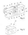
- linear slide 20 primarily consists of linear rail 22 and slider body 24 which is adapted to axially translate across linear rail 22.
- slider body 24 which is adapted to axially translate across linear rail 22.
- a pair of linear rails 22 is typically used in most applications and provided in opposing orientation.
- a platform or other article in need of linear movement can then be attached to the two slider bodies to allow for reciprocating movement.
- the article being moved back and forth across the rails 22 be moved in a perfect or substantially perfect plane with substantially no movement orthogonal to the linear rail. Since the linear rail 22 is comprised of an upper raceway 26 and parallel lower raceway 28 any departure of the raceways from a uniform distance therebetween, will result in undesirable orthogonal movement of the slider body 24. Even if the linear rail 22 is manufactured perfectly, over a period of time, the upper raceway 26 and lower raceway 28 can deflect out of a perfect plane due to excessively high loads, shock loads, or thermal expansion.
- the present invention therefore provides a slider body 24 with a mechanism for ensuring contact of the rollers of the slider body with upper raceway 26 and lower raceway 28.
- slider body 24 accomplishes this objective by providing two rollers 30 which are mechanically biased in a downward direction indicated by arrow 32 and a middle roller 34 which is adjustable in the vertical direction by adjustment block 36.
- each roller is mounted onto shaft 38 with shaft 38 being attached to slider body 24 by a mechanical spring 40. It is to be understood that this selection of elements is only used in the preferred embodiment, and that in alternative embodiments, there are other types of biasing means that can be used to generate a downward force upon rollers 30. It is also to be understood that in the preferred embodiment only three rollers are used for each slider body 24, but that in alternative embodiments, a different number of rollers can certainly be employed with equal efficacy using the same basis of the present invention.
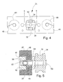
- adjustment block 36 it can be seen from FIG. 3 that it is a substantially "T" shaped block having planar portion 42 and rearwardly extending leg 44. Planar portion 42 is sized to fit into notch 46 of slider body 24, while leg 44 is proportionately smaller in size to fit into vertical slot 48 (FIG. 5). In so doing, adjustment block 36 is adapted for vertical movement as leg 44 slides within slot 48. By moving adjustment block 36 in a vertical direction, roller 34 is also moved in a vertical direction since middle roller 34 is attached to adjustment block 36 using stud 50. The relative position of adjustment block 36 within notch 46 can be adjusted using set screws 52.
- position adjustment block 36 can be modified.
- a spacer or washer 54 separates roller 34 from adjustment block 36 and from slider body 24.
- position adjustment means other than set screws can be employed, such as wedges, cams, spacers, solenoids, piezoelectric mechanisms, rack and pinion and springs.
- the present invention provides a mechanism by which contact between rollers 30 and roller 34 with lower raceway 28 and upper raceway 26, respectively, can be ensured regardless of the parallelism between upper raceway 26 and lower raceway 28. Moreover, by attaching rollers 30 to slider body 24 using mechanical springs 40 a certain degree of elasticity is provided which enables the slider body 24 to absorb considerable shock loads. It is to be understood that while the preferred embodiment uses mechanical springs 40 manufactured from metal, any type of elastomeric material can be used provided it has sufficient rigidity to support the weight to be carried by slider body 24.
- middle roller 34 on adjustment block 36
- the entire system 20 can be preloaded to ensure proper functioning of the system.
- the slide system can add rigidity but still maintain a smooth actuation and low co-efficient of friction.
- a properly set, rigid preload setting is difficult to manufacture into a slide system because of, inter alia , tolerance stack ups, so a means of adjusting the preload is necessary.
- the rolling device is tightened against the housing material and not the adjustment block. This creates a very rigid mount for the rolling device.
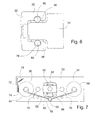
- FIG. 7 depicts a side view of alternative slider body 24.
- the alternative embodiment uses the identical adjustment block arrangement discussed above, but provides a different means for elastically mounting outside rollers 30.
- rollers 30 are mounted using a coil spring mounted about pivot 58.
- the coil spring 60 has first leg 62 adapted to mount first roller 64, while coil spring 60 also has a second leg 66 for mounting a third roller 68 as indicated by bi-directional arrows 70.
- First roller 64 and third roller 68 are therefore allowed a certain degree of vertical play to accept fairly substantial shock loads.
- a brush 72 is provided with abrasive surface 74 to clean rollers 30. It can be seen that brush 72 is spring biased toward rollers 30 using spring 76 to ensure proper and sufficient load against rollers 30 for adequately cleaning purposes. This is of importance, because as can be seen from FIGS. 5 and 6, each roller 30 is provided with an annular groove 78 which is sized to receive hardened raceway insert 80. Any contaminants provided between the roller and raceway will necessarily effect the accuracy of the linear slide system 20.
- one factor which can effect the accuracy of the system 20 is rail misalignment or loss of parallelism due to use over time.
- One feature which the present invention provides to avoid such expansion is the use of hardened raceway inserts 80.
- the raceways are manufactured of hardened steel while rollers are manufactured with 52100 steel.
- Rails 22 are preferably manufactured of 6061-T6 aluminum as are slider bodies 24.
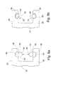
- FIGS. 8A and 8B depict the manner in which raceway inserts 80 are inserted into rails 22 in the preferred embodiment.
- inserts 80 are substantially cylindrical but do include a flattened surface 82 such that the diameter of the insert 80 proximate the flattened surface 82 is less than the opening 84 provided in linear rail 22 to channel 86.
- the diameter of channel 86 is larger than the diameter of raceway insert 80 even at its largest point to ensure that raceway insert 80 can fit within channels 86.
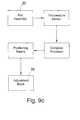
- the present invention can be adapted to provide a sensor to detect the actual position of upper raceway 26 and lower raceway 28 and adjust the position of rollers 30 accordingly.
- a temperature sensor such as a thermocouple can be used to monitor the temperature of raceways 26 and 28 as well as that of rollers 30 to position the rollers 30 based on thermal expansion such that slider body 24 traverses along a substantially uniform plane.
- FIGS. 10-12 represent another alternate embodiment of the present invention. While similar to the previous embodiments, the present embodiment provides an alternate mechanism for adjusting and fixing the position of the adjustment block 36 which mounts a roller 34 to the slider body 24, and also makes clear that biasing means such as the mechanical springs 40 are not required to employ the present invention.
- a unique feature of the present invention is that while the adjusting means provide highly accurate positioning of the roller 34, the adjusting mechanism (such as set screws 52 depicted in FIGS. 2 and 4) is accessible from the top and bottom surface of the slider body 24. Therefore, when a platform or other item is attached to the side of the slider body 24 via mounting holes 110, the position of the roller 34 may still be adjusted because the adjusting mechanism remains accessible from the top and bottom. It may also be desirable to provide access to the adjusting mechanism from only one side, i.e. the top or bottom sides, of the slider body 24.
- FIGS. 10-12 represent an alternate embodiment of the present invention wherein the mechanism for adjusting the block 36 and roller 34 are provided from one side, namely the top side of the slider body 24.
- a pair of threaded bolts 101, 102 provide adjustment of the adjustment block 36 and hence roller 34 which is attached thereto.
- the bolts 101, 102 exert opposing forces on the adjustment block 36 and roller 34 to adjust the position of the roller 34 relative to the upper and lower raceways 26, 28.
- bolt 101 exerts a downward vertical force on the adjustment block 36
- bolt 102 exerts an upward vertical force on the adjustment block 36.
- bolt 101 threadingly engages the slider body 24 through tapped hole 103 which extends from a top surface 124 of the slider body 24 downwardly into the notch 46 which houses the adjustment block 36.
- a downward end of the bolt 101 engages the top side of the adjustment block 36 such that when the bolt 101 is turned clockwise, screwing the bolt 101 into the slider body 24, the bolt 101 induces a downward force on the adjustment block 36 and hence roller 34.
- Bolt 102 induces an upwardly and vertically directed force on the adjustment block 36 in opposition to the downward force of bolt 101.
- bolt 102 does not threadingly engage the slider body 24, but includes a head 104 which is larger than an aperture 105 formed in the slider body 24.
- the aperture 105 connects the upper surface 124 with the internal notch 46.
- a bottom end of the bolt 102 includes threads which cooperate with the threaded hole 106 formed through the adjustment block 36.
- the head 104 of the bolt engages the top surface 124 of the body 24, while the threads engage threaded aperture 106 and pull the adjustment block 36 upwardly.
- the two bolts 101, 102 may be rotated, either in sequence or at the same time, to vertically adjust the position of the block 36 and roller 34 within the notch 46, by virtue of opposing upwardly and downwardly directed vertical forces.
- bolt 101 may be loosened to eliminate the downward force on block 36 and provide some vertical clearance. Then, bolt 102 may be rotated to induce further upward vertical force on the block 36 moving the roller 34 upwardly until it reaches the desired position, typically engaging the upper raceway 26 of the rail 22. Finally, bolt 101 may be retightened to engage the block 36 and induce an equal and opposite downward vertical force on the block 36 to firmly fix its position within the notch 46, and hence the position of roller 34 within the rail 22. Therefore, bolts 101 and 102 are capable of adjusting the position of the roller 34 while remaining accessible from one side, illustrated as the top side, of the slider body 24. Therefore, the linear rail system may be adjusted even while a platform or other item is attached to the slider body 24 or slider bodies, and the system may be easily accurately pre-loaded.
- the present invention provides a new and improved linear slide system with an apparatus for adjusting the preload on the slider body rollers.
- the slider body By adequately adjusting the preload, the slider body will be assured of maintaining a proper plane during operation even if subjected to substantial loads.
- the slider body By mounting at least one of the rollers using a biasing means, the slider body will be able to handle substantial shock loads as the slider body traverses across linear rail.
- the provision of hardened metal raceway inserts assist with the parallelism of the upper and lower raceways over time.
Landscapes
- Engineering & Computer Science (AREA)
- General Engineering & Computer Science (AREA)
- Mechanical Engineering (AREA)
- Bearings For Parts Moving Linearly (AREA)
Applications Claiming Priority (2)
| Application Number | Priority Date | Filing Date | Title |
|---|---|---|---|
| US09/695,620 US6450687B1 (en) | 1998-12-14 | 2000-10-24 | Linear rail system having preload adjustment apparatus |
| US695620 | 2000-10-24 |
Publications (3)
| Publication Number | Publication Date |
|---|---|
| EP1203891A2 true EP1203891A2 (fr) | 2002-05-08 |
| EP1203891A3 EP1203891A3 (fr) | 2004-07-14 |
| EP1203891B1 EP1203891B1 (fr) | 2009-02-25 |
Family
ID=24793767
Family Applications (1)
| Application Number | Title | Priority Date | Filing Date |
|---|---|---|---|
| EP01203961A Expired - Lifetime EP1203891B1 (fr) | 2000-10-24 | 2001-10-16 | Assemblage de glissière linéaire comprenant un dispositif à réglage de la précharge |
Country Status (3)
| Country | Link |
|---|---|
| US (1) | US6450687B1 (fr) |
| EP (1) | EP1203891B1 (fr) |
| DE (1) | DE60137747D1 (fr) |
Cited By (3)
| Publication number | Priority date | Publication date | Assignee | Title |
|---|---|---|---|---|
| ITMI20130556A1 (it) * | 2013-04-09 | 2014-10-10 | Molteni & C | Tavolo con meccanismo di allunga |
| WO2015112544A1 (fr) * | 2014-01-22 | 2015-07-30 | Parker-Hannifin Corporation | Dispositif de précharge de roue d'un guide linéaire |
| CN115405761A (zh) * | 2022-08-12 | 2022-11-29 | 北京金河水务建设集团有限公司 | 一种竖向滑动轨道固定装置 |
Families Citing this family (12)
| Publication number | Priority date | Publication date | Assignee | Title |
|---|---|---|---|---|
| US20070230838A1 (en) * | 2006-03-28 | 2007-10-04 | Steven Fulton | Compliant rail linear guide |
| US20080245641A1 (en) | 2007-04-06 | 2008-10-09 | Pacific Bearing Company | Tamper-Proof Roller Mounting Arrangement and Method |
| US8684605B2 (en) | 2008-03-07 | 2014-04-01 | Pacific Bearing Company | Guide rail |
| US8070361B2 (en) * | 2008-05-19 | 2011-12-06 | Pacific Bearing Company | Linear rail system having preload adjustment mechanism |
| CA2795066A1 (fr) * | 2010-03-31 | 2011-10-06 | Jason Paulman | Appareil a banc humide et procede associe |
| ITMI20130558A1 (it) * | 2013-04-09 | 2014-10-10 | Molteni & C | Meccanismo di estensione di un piano di appoggio |
| US9316261B2 (en) * | 2014-02-10 | 2016-04-19 | NADELLA S.r.l. | Linear guide system |
| JP6850214B2 (ja) * | 2016-08-08 | 2021-03-31 | Thk株式会社 | 移動体保持具及び移動体 |
| US11105366B2 (en) | 2018-06-12 | 2021-08-31 | Haydon Kerk Motion Solutions, Inc. | Long span lead screw assembly with anti-backlash nut and wear compensated load bearing element |
| US11433464B2 (en) * | 2018-08-28 | 2022-09-06 | Techtronic Power Tools Technology Limited | Tile saw |
| CN113107973A (zh) * | 2019-03-04 | 2021-07-13 | 余斯婷 | 一种室内设计用预埋型绿化的滑动轨道 |
| US11001146B2 (en) * | 2019-04-05 | 2021-05-11 | Caterpillar Paving Products Inc. | Machine console system |
Family Cites Families (13)
| Publication number | Priority date | Publication date | Assignee | Title |
|---|---|---|---|---|
| US1926828A (en) | 1927-02-02 | 1933-09-12 | U S Slieing Machine Company | Guide for slicing machines |
| US1923853A (en) | 1928-02-07 | 1933-08-22 | Us Slicing Machine Co | Slicing machine guide |
| US2598251A (en) | 1946-10-31 | 1952-05-27 | Edwin E Gesner | Tool supporting carriage |
| US3019072A (en) | 1960-08-08 | 1962-01-30 | Gen Precision Inc | X-y plotter |
| US3661431A (en) | 1970-08-24 | 1972-05-09 | Bishop Wisecarver Corp | Guide wheels and tracks |
| DE2300692A1 (de) | 1973-01-08 | 1974-07-25 | Spellmann Georg Hannover Holz | Teile zur aufhaengung und fuehrung von schiebetueren |
| US4390216A (en) | 1981-09-16 | 1983-06-28 | Camsco, Inc. | Carriage having integral spring |
| US4884898A (en) * | 1989-02-06 | 1989-12-05 | Lee Controls, Inc. | Linear motion pillow block including fine tuning features |
| US5440999A (en) | 1992-06-03 | 1995-08-15 | Dallman Industrial Corporation | Modular transport system for an automatic teller machine |
| JP2750821B2 (ja) | 1994-10-17 | 1998-05-13 | プルトンチエン株式会社 | ローラー型直線案内装置 |
| US5915840A (en) * | 1994-10-20 | 1999-06-29 | Knight Industries, Inc. | Linear guideway arrangement |
| FR2771326B3 (fr) | 1997-11-27 | 1999-11-12 | Jui Kun Lin | Mecanisme pour assurer le mouvement lineaire d'un bras mecanique |
| US6149308A (en) * | 1998-12-14 | 2000-11-21 | Pacific Bearing Company | Linear rail system having preload adjustment apparatus |
-
2000
- 2000-10-24 US US09/695,620 patent/US6450687B1/en not_active Expired - Lifetime
-
2001
- 2001-10-16 DE DE60137747T patent/DE60137747D1/de not_active Expired - Lifetime
- 2001-10-16 EP EP01203961A patent/EP1203891B1/fr not_active Expired - Lifetime
Cited By (4)
| Publication number | Priority date | Publication date | Assignee | Title |
|---|---|---|---|---|
| ITMI20130556A1 (it) * | 2013-04-09 | 2014-10-10 | Molteni & C | Tavolo con meccanismo di allunga |
| WO2015112544A1 (fr) * | 2014-01-22 | 2015-07-30 | Parker-Hannifin Corporation | Dispositif de précharge de roue d'un guide linéaire |
| US9869348B2 (en) | 2014-01-22 | 2018-01-16 | Parker-Hannifin Corporation | Wheel preload device |
| CN115405761A (zh) * | 2022-08-12 | 2022-11-29 | 北京金河水务建设集团有限公司 | 一种竖向滑动轨道固定装置 |
Also Published As
| Publication number | Publication date |
|---|---|
| DE60137747D1 (de) | 2009-04-09 |
| EP1203891A3 (fr) | 2004-07-14 |
| US6450687B1 (en) | 2002-09-17 |
| EP1203891B1 (fr) | 2009-02-25 |
Similar Documents
| Publication | Publication Date | Title |
|---|---|---|
| US6149308A (en) | Linear rail system having preload adjustment apparatus | |
| US6450687B1 (en) | Linear rail system having preload adjustment apparatus | |
| US6476525B2 (en) | Linear actuator | |
| US8070361B2 (en) | Linear rail system having preload adjustment mechanism | |
| US7607835B2 (en) | Linear guide device with preload-adjustment device | |
| JP4838402B1 (ja) | ステージ機構 | |
| US7481126B2 (en) | Precision table | |
| EP3819522B1 (fr) | Système de mouvement linéaire | |
| JPH07190056A (ja) | 直動ユニットにおけるトラックレール取付構造 | |
| JPH07109646A (ja) | 丸編機のシリンダー基筒部におけるベアリング装置 | |
| US3360306A (en) | Slide bearing assembly | |
| WO2020121562A1 (fr) | Mécanisme de platine | |
| US9693633B2 (en) | Seat adjustment system | |
| EP2380265A1 (fr) | Entraînement direct linéaire électrodynamique | |
| US20250052270A1 (en) | Feed mechanism and method for manufacturing same | |
| US5362157A (en) | Linear motion rolling guide unit | |
| US6290395B1 (en) | Linear slide assembly | |
| JP2575926B2 (ja) | 直線案内装置 | |
| JPH075298Y2 (ja) | 直動テーブルユニット | |
| JP2603645Y2 (ja) | 直線作動ユニット | |
| US10012296B2 (en) | Compensating drive nut assembly | |
| JPS63308264A (ja) | 直線運動案内機構の予圧調整装置 | |
| CN120871369A (zh) | 一种薄形大面积位移台 | |
| CA2791137C (fr) | Systeme de reglage de siege | |
| JPH07190054A (ja) | 直動ユニットにおけるトラックレール取付構造 |
Legal Events
| Date | Code | Title | Description |
|---|---|---|---|
| PUAI | Public reference made under article 153(3) epc to a published international application that has entered the european phase |
Free format text: ORIGINAL CODE: 0009012 |
|
| AK | Designated contracting states |
Kind code of ref document: A2 Designated state(s): AT BE CH CY DE DK ES FI FR GB GR IE IT LI LU MC NL PT SE TR |
|
| AX | Request for extension of the european patent |
Free format text: AL;LT;LV;MK;RO;SI |
|
| PUAL | Search report despatched |
Free format text: ORIGINAL CODE: 0009013 |
|
| AK | Designated contracting states |
Kind code of ref document: A3 Designated state(s): AT BE CH CY DE DK ES FI FR GB GR IE IT LI LU MC NL PT SE TR |
|
| AX | Request for extension of the european patent |
Extension state: AL LT LV MK RO SI |
|
| 17P | Request for examination filed |
Effective date: 20050106 |
|
| AKX | Designation fees paid |
Designated state(s): CH DE FR GB IT LI |
|
| 17Q | First examination report despatched |
Effective date: 20050531 |
|
| 17Q | First examination report despatched |
Effective date: 20050531 |
|
| GRAP | Despatch of communication of intention to grant a patent |
Free format text: ORIGINAL CODE: EPIDOSNIGR1 |
|
| GRAS | Grant fee paid |
Free format text: ORIGINAL CODE: EPIDOSNIGR3 |
|
| GRAA | (expected) grant |
Free format text: ORIGINAL CODE: 0009210 |
|
| AK | Designated contracting states |
Kind code of ref document: B1 Designated state(s): CH DE FR GB IT LI |
|
| REG | Reference to a national code |
Ref country code: GB Ref legal event code: FG4D |
|
| REG | Reference to a national code |
Ref country code: CH Ref legal event code: EP |
|
| REF | Corresponds to: |
Ref document number: 60137747 Country of ref document: DE Date of ref document: 20090409 Kind code of ref document: P |
|
| REG | Reference to a national code |
Ref country code: CH Ref legal event code: NV Representative=s name: CABINET ROLAND NITHARDT CONSEILS EN PROPRIETE INDU |
|
| PLBE | No opposition filed within time limit |
Free format text: ORIGINAL CODE: 0009261 |
|
| STAA | Information on the status of an ep patent application or granted ep patent |
Free format text: STATUS: NO OPPOSITION FILED WITHIN TIME LIMIT |
|
| PGFP | Annual fee paid to national office [announced via postgrant information from national office to epo] |
Ref country code: DE Payment date: 20091028 Year of fee payment: 9 |
|
| 26N | No opposition filed |
Effective date: 20091126 |
|
| PGFP | Annual fee paid to national office [announced via postgrant information from national office to epo] |
Ref country code: GB Payment date: 20091026 Year of fee payment: 9 |
|
| REG | Reference to a national code |
Ref country code: CH Ref legal event code: PL |
|
| REG | Reference to a national code |
Ref country code: FR Ref legal event code: ST Effective date: 20100630 |
|
| PG25 | Lapsed in a contracting state [announced via postgrant information from national office to epo] |
Ref country code: FR Free format text: LAPSE BECAUSE OF NON-PAYMENT OF DUE FEES Effective date: 20091102 |
|
| PG25 | Lapsed in a contracting state [announced via postgrant information from national office to epo] |
Ref country code: LI Free format text: LAPSE BECAUSE OF NON-PAYMENT OF DUE FEES Effective date: 20091031 Ref country code: CH Free format text: LAPSE BECAUSE OF NON-PAYMENT OF DUE FEES Effective date: 20091031 |
|
| PG25 | Lapsed in a contracting state [announced via postgrant information from national office to epo] |
Ref country code: IT Free format text: LAPSE BECAUSE OF NON-PAYMENT OF DUE FEES Effective date: 20091016 |
|
| GBPC | Gb: european patent ceased through non-payment of renewal fee |
Effective date: 20101016 |
|
| PG25 | Lapsed in a contracting state [announced via postgrant information from national office to epo] |
Ref country code: GB Free format text: LAPSE BECAUSE OF NON-PAYMENT OF DUE FEES Effective date: 20101016 |
|
| REG | Reference to a national code |
Ref country code: DE Ref legal event code: R119 Ref document number: 60137747 Country of ref document: DE Effective date: 20110502 |
|
| PG25 | Lapsed in a contracting state [announced via postgrant information from national office to epo] |
Ref country code: DE Free format text: LAPSE BECAUSE OF NON-PAYMENT OF DUE FEES Effective date: 20110502 |