EP1205563A1 - Oberflächen-Entkoklung eines Bohrer mit rafinierter Primärschneidkante - Google Patents
Oberflächen-Entkoklung eines Bohrer mit rafinierter Primärschneidkante Download PDFInfo
- Publication number
- EP1205563A1 EP1205563A1 EP01204918A EP01204918A EP1205563A1 EP 1205563 A1 EP1205563 A1 EP 1205563A1 EP 01204918 A EP01204918 A EP 01204918A EP 01204918 A EP01204918 A EP 01204918A EP 1205563 A1 EP1205563 A1 EP 1205563A1
- Authority
- EP
- European Patent Office
- Prior art keywords
- cutting
- drill
- flutes
- rake
- cutting tip
- Prior art date
- Legal status (The legal status is an assumption and is not a legal conclusion. Google has not performed a legal analysis and makes no representation as to the accuracy of the status listed.)
- Withdrawn
Links
- 238000005520 cutting process Methods 0.000 title claims abstract description 106
- 238000005261 decarburization Methods 0.000 title description 2
- 238000000034 method Methods 0.000 claims abstract description 26
- 230000001681 protective effect Effects 0.000 claims abstract description 6
- 229910017052 cobalt Inorganic materials 0.000 claims description 8
- 239000010941 cobalt Substances 0.000 claims description 8
- GUTLYIVDDKVIGB-UHFFFAOYSA-N cobalt atom Chemical compound [Co] GUTLYIVDDKVIGB-UHFFFAOYSA-N 0.000 claims description 8
- 229910052751 metal Inorganic materials 0.000 claims description 5
- 239000002184 metal Substances 0.000 claims description 5
- 229910003460 diamond Inorganic materials 0.000 claims description 4
- 239000010432 diamond Substances 0.000 claims description 4
- WFKWXMTUELFFGS-UHFFFAOYSA-N tungsten Chemical compound [W] WFKWXMTUELFFGS-UHFFFAOYSA-N 0.000 claims description 3
- 229910052721 tungsten Inorganic materials 0.000 claims description 3
- 239000010937 tungsten Substances 0.000 claims description 3
- UONOETXJSWQNOL-UHFFFAOYSA-N tungsten carbide Chemical compound [W+]#[C-] UONOETXJSWQNOL-UHFFFAOYSA-N 0.000 claims description 3
- 238000010438 heat treatment Methods 0.000 claims 1
- 239000000203 mixture Substances 0.000 description 7
- 238000005553 drilling Methods 0.000 description 6
- 150000001247 metal acetylides Chemical class 0.000 description 6
- 239000001257 hydrogen Substances 0.000 description 5
- 229910052739 hydrogen Inorganic materials 0.000 description 5
- CURLTUGMZLYLDI-UHFFFAOYSA-N Carbon dioxide Chemical compound O=C=O CURLTUGMZLYLDI-UHFFFAOYSA-N 0.000 description 4
- -1 Co3W3C or Co3W6C Chemical compound 0.000 description 3
- UFHFLCQGNIYNRP-UHFFFAOYSA-N Hydrogen Chemical compound [H][H] UFHFLCQGNIYNRP-UHFFFAOYSA-N 0.000 description 3
- 239000007789 gas Substances 0.000 description 3
- 239000000843 powder Substances 0.000 description 3
- 238000007670 refining Methods 0.000 description 3
- XKRFYHLGVUSROY-UHFFFAOYSA-N Argon Chemical compound [Ar] XKRFYHLGVUSROY-UHFFFAOYSA-N 0.000 description 2
- QVGXLLKOCUKJST-UHFFFAOYSA-N atomic oxygen Chemical compound [O] QVGXLLKOCUKJST-UHFFFAOYSA-N 0.000 description 2
- 239000011230 binding agent Substances 0.000 description 2
- 229910052799 carbon Inorganic materials 0.000 description 2
- 239000001569 carbon dioxide Substances 0.000 description 2
- 229910002092 carbon dioxide Inorganic materials 0.000 description 2
- 230000007547 defect Effects 0.000 description 2
- 150000002431 hydrogen Chemical class 0.000 description 2
- 239000000463 material Substances 0.000 description 2
- 239000001301 oxygen Substances 0.000 description 2
- 229910052760 oxygen Inorganic materials 0.000 description 2
- 238000003825 pressing Methods 0.000 description 2
- 238000005245 sintering Methods 0.000 description 2
- OKTJSMMVPCPJKN-UHFFFAOYSA-N Carbon Chemical compound [C] OKTJSMMVPCPJKN-UHFFFAOYSA-N 0.000 description 1
- RYGMFSIKBFXOCR-UHFFFAOYSA-N Copper Chemical compound [Cu] RYGMFSIKBFXOCR-UHFFFAOYSA-N 0.000 description 1
- 239000004593 Epoxy Substances 0.000 description 1
- 229910052786 argon Inorganic materials 0.000 description 1
- 229910052802 copper Inorganic materials 0.000 description 1
- 239000010949 copper Substances 0.000 description 1
- 230000002950 deficient Effects 0.000 description 1
- 238000009826 distribution Methods 0.000 description 1
- 230000000694 effects Effects 0.000 description 1
- 239000011152 fibreglass Substances 0.000 description 1
- 239000000446 fuel Substances 0.000 description 1
- 239000010410 layer Substances 0.000 description 1
- 230000004048 modification Effects 0.000 description 1
- 238000012986 modification Methods 0.000 description 1
- 239000002344 surface layer Substances 0.000 description 1
Images


Classifications
-
- B—PERFORMING OPERATIONS; TRANSPORTING
- B24—GRINDING; POLISHING
- B24D—TOOLS FOR GRINDING, BUFFING OR SHARPENING
- B24D3/00—Physical features of abrasive bodies, or sheets, e.g. abrasive surfaces of special nature; Abrasive bodies or sheets characterised by their constituents
- B24D3/02—Physical features of abrasive bodies, or sheets, e.g. abrasive surfaces of special nature; Abrasive bodies or sheets characterised by their constituents the constituent being used as bonding agent
- B24D3/20—Physical features of abrasive bodies, or sheets, e.g. abrasive surfaces of special nature; Abrasive bodies or sheets characterised by their constituents the constituent being used as bonding agent and being essentially organic
- B24D3/22—Rubbers synthetic or natural
- B24D3/26—Rubbers synthetic or natural for porous or cellular structure
-
- B—PERFORMING OPERATIONS; TRANSPORTING
- B23—MACHINE TOOLS; METAL-WORKING NOT OTHERWISE PROVIDED FOR
- B23B—TURNING; BORING
- B23B51/00—Tools for drilling machines
- B23B51/02—Twist drills
-
- B—PERFORMING OPERATIONS; TRANSPORTING
- B24—GRINDING; POLISHING
- B24B—MACHINES, DEVICES, OR PROCESSES FOR GRINDING OR POLISHING; DRESSING OR CONDITIONING OF ABRADING SURFACES; FEEDING OF GRINDING, POLISHING, OR LAPPING AGENTS
- B24B3/00—Sharpening cutting edges, e.g. of tools; Accessories therefor, e.g. for holding the tools
- B24B3/24—Sharpening cutting edges, e.g. of tools; Accessories therefor, e.g. for holding the tools of drills
- B24B3/26—Sharpening cutting edges, e.g. of tools; Accessories therefor, e.g. for holding the tools of drills of the point of twist drills
-
- C—CHEMISTRY; METALLURGY
- C21—METALLURGY OF IRON
- C21D—MODIFYING THE PHYSICAL STRUCTURE OF FERROUS METALS; GENERAL DEVICES FOR HEAT TREATMENT OF FERROUS OR NON-FERROUS METALS OR ALLOYS; MAKING METAL MALLEABLE, e.g. BY DECARBURISATION OR TEMPERING
- C21D3/00—Diffusion processes for extraction of non-metals; Furnaces therefor
- C21D3/02—Extraction of non-metals
- C21D3/04—Decarburising
-
- C—CHEMISTRY; METALLURGY
- C21—METALLURGY OF IRON
- C21D—MODIFYING THE PHYSICAL STRUCTURE OF FERROUS METALS; GENERAL DEVICES FOR HEAT TREATMENT OF FERROUS OR NON-FERROUS METALS OR ALLOYS; MAKING METAL MALLEABLE, e.g. BY DECARBURISATION OR TEMPERING
- C21D9/00—Heat treatment, e.g. annealing, hardening, quenching or tempering, adapted for particular articles; Furnaces therefor
- C21D9/22—Heat treatment, e.g. annealing, hardening, quenching or tempering, adapted for particular articles; Furnaces therefor for drills; for milling cutters; for machine cutting tools
-
- B—PERFORMING OPERATIONS; TRANSPORTING
- B23—MACHINE TOOLS; METAL-WORKING NOT OTHERWISE PROVIDED FOR
- B23B—TURNING; BORING
- B23B2228/00—Properties of materials of tools or workpieces, materials of tools or workpieces applied in a specific manner
- B23B2228/10—Coatings
-
- B—PERFORMING OPERATIONS; TRANSPORTING
- B23—MACHINE TOOLS; METAL-WORKING NOT OTHERWISE PROVIDED FOR
- B23B—TURNING; BORING
- B23B2251/00—Details of tools for drilling machines
- B23B2251/12—Cross sectional views of the cutting edges
- B23B2251/122—Bevelled cutting edges
-
- B—PERFORMING OPERATIONS; TRANSPORTING
- B23—MACHINE TOOLS; METAL-WORKING NOT OTHERWISE PROVIDED FOR
- B23B—TURNING; BORING
- B23B2251/00—Details of tools for drilling machines
- B23B2251/12—Cross sectional views of the cutting edges
- B23B2251/125—Rounded cutting edges
-
- B—PERFORMING OPERATIONS; TRANSPORTING
- B23—MACHINE TOOLS; METAL-WORKING NOT OTHERWISE PROVIDED FOR
- B23B—TURNING; BORING
- B23B2251/00—Details of tools for drilling machines
- B23B2251/18—Configuration of the drill point
-
- B—PERFORMING OPERATIONS; TRANSPORTING
- B23—MACHINE TOOLS; METAL-WORKING NOT OTHERWISE PROVIDED FOR
- B23B—TURNING; BORING
- B23B51/00—Tools for drilling machines
- B23B51/011—Micro drills
Definitions
- the present invention relates generally to a method of surface decarburizing a drill bit and more particularly to a method of surface decarburizing cemented carbide microdrills.
- Microdrills generally range in diameter from about 0.002 inches to 0.125 inches. Microdrills are typically employed to form holes in single sided, double sided, and multilayer printed circuit board laminates. Microdrills may additionally be employed in any application where small holes of carefully controlled dimensions are required. Such additional applications include cameras, watches, fuel injectors and the like.
- Microdrills for drilling holes in printed circuit boards must have sufficient strength and resistance to wear to satisfy the requirements of the industry. Accordingly, it is common to make such microdrills of cemented carbide to provide the strength and hardness required.
- a disadvantage of using cemented carbide is its brittleness which causes such microdrills to be prone to chipping. This is especially so at the outer corner of the cutting edge of the drill bit which defines the wall of the hole drilled in the printed circuit board. This proneness to chipping of cemented carbide drills has been recognized previously. See U.S. Patent No. 4,583,888 issued to Mori, et al., and U.S. Patent No. 4,642,003 issued to Yoshimura. After the drill bit has become chipped, wear of the drill bit is accelerated.
- the present invention alleviates to a great extent the disadvantages of the prior art by providing a method of surface decarburizing a cemented carbide microdrill to make the microdrill more chip and wear resistant.
- a process of surface decarburizing a cemented carbide microdrill in which a hardened outer surface layer is formed thereon that comprises eta phase, a double carbide of tungsten and cobalt, and tungsten carbide WC and cobalt metal.
- the primary cutting edges of the microdrill are strengthened by refining the cutting edges by forming an angular surface ("K land") adjacent to the cutting edge.
- a process of surface decarburizing a cemented carbide microdrill wherein the surface decarburizing is performed following a refining of the primary cutting edges of the microdrill by forming a radius or angular surface thereon so as to provide wear and chip resistant cutting edges.
- a process of surface decarburizing a cemented carbide microdrill having a refined primary cutting edge to increase resistance to wear and chipping is provided.
- a process of mass producing a refined rounded primary cutting edge on a microdrill is provided.
- Cemented carbide microdrills are generally made by pressing and sintering a mixture of powders of one or more metallic carbides and a smaller amount of metal such as cobalt to serve as a binder.
- Cemented carbides have a very high hardness and strength which makes it an advantageous material to use in the drilling applications described above.
- cemented carbides are also brittle. This can lead to chipping, especially at the outer corners of the primary cutting edges.
- the purpose of surface decarburizing microdrills is to increase resistance of the cemented carbide to wear and chipping.
- the surface decarburizing process obtains a thin (less than 1 micron) wear resistant layer that comprises eta phase (carbon deficient carbide), a double carbide of tungsten and cobalt, e.g., Co 3 W 3 C or Co 3 W 6 C, as well as tungsten carbide WC and cobalt metal.
- Surface decarburizing of the cemented carbide microdrill is done at a temperature from 600°C to 1100°C for 15 to 120 minutes.
- the surface decarburizing process requires a controlled partial pressure of decarburizing gas, e.g., hydrogen, carbon dioxide, oxygen and other mixtures, with hydrogen being preferred, amid the general protective environment at the heat treating temperature.
- decarburizing is preferably done at approximately 800°C for approximately 60 minutes in the mixture of decarburizing gas.
- the above surface decarburizing process may also be advantageously used on microdrills having refined cutting edges to further increase resistance to wear and chipping.
- the refinements may be made, for example, by various known honing methods. These refinements to the primary cutting edge of the surface decarburized cemented carbide microdrill are discussed below.
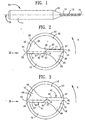
- FIG. 1 illustrates a side elevation of an embodiment of a microdrill according to the present invention.
- a microdrill is generally illustrated at 10 as comprising a shank 11, a tapered section 12, and a drill body 13.
- the drill body 13 may be provided with a slight inward taper toward the shank to provide clearance with respect to the wall of the hole being drilled.
- the drill body 13 comprises a cutting tip 14 and a plurality of flutes 15.
- the flutes extend from the cutting tip 14 and terminate in the tapered section 12.
- the wall of the flute at the primary cutting edge is defined by the rake surface 17.
- the microdrill has a longitudinal axis of symmetry 16. Wherever the elements of microdrill 10 are common to the embodiments described below, consistent numbering is used.
- FIG. 2 illustrates a view of the cutting tip of the first embodiment of a microdrill according to the present invention.
- the point end has primary cutting edges 20 formed at the intersection of the flank surfaces 27 with the rake surface 17.
- the primary cutting edges 20 have been refined by forming radius surfaces 21.
- the term radius surface is used throughout to indicate any curvilinear modification to the cutting edge, not limited to a true or constant radius.
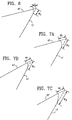
- This configuration can best be seen in FIG. 5A which shows radius surface 21 formed at primary cutting edge 20 at the intersection of flank surface 27 and rake surface 17.
- Radius surface 21 extends from the forward end of the flank surface 27 to the rake surface 17.
- Radius surface 21 can extend along all or any portion of the primary cutting edge 20, preferably extending from the outer corner of primary cutting edge 20.
- FIG. 5B shows an alternate radius surface geometry having a curvilinear radius surface 21 with a "waterfall" on the flank surface 27.
- the radius surface 21 has a waterfall on the rake surface 1.7.
- the distance W1 between an imaginary point where the flank surface 27 would intersect rake surface 17 and the point where the radius surface 21 intersects the flank surface 27 is at least about .0001 inches.
- the distance W2 between this imaginary point and the point where the radius surface 21 intersects the rake surface 17, is also at least about .0001 inches.
- the cutting tip additionally has side blades 22 which are formed between the flutes 15.
- the side blades 22 have a wing-shaped cross section and are connected together at axis 16 by the web 23.
- Side blades 22 spiral along the length of drill body 13 and have margins 24 at outer diameter 25.
- the portion of side blades 22 trailing margins 24 has reduced diameter 26 referred to as a side blade clearance diameter.
- Secondary surfaces 28 may be formed on the trailing edge of flank surfaces 27. In such a configuration, the intersection of secondary surface 28 with the opposite flank surface 27 forms chisel edge 29.
- the microdrill is rotated in direction A and thrust forward to the work piece. All cutting edges are leading edges with respect to that direction of rotation.
- FIG. 3 illustrates a view of the cutting tip of the second embodiment of a microdrill according to the present invention.
- the point end has primary cutting edges 40 formed at the intersection of flank surfaces 47 with the rake surface 17.
- the primary cutting edges 40 have been refined by forming angular surfaces 41 ("K land").
- K land angular surfaces 41
- FIG. 6 shows angular surface 41 formed at the primary cutting edge 40 at the intersection of flank surface 47 and rake surface 17.
- Angular surface 41 is formed on the forward end of rake surface 17.
- Angular surface 41 can extend along all or a portion of primary cutting edge 40, preferably extending from the outer corner of the primary cutting edge 40.
- the distance W1 between an imaginary point where the flank surface 47 would intersect the rake surface 17 and the point where the angular surface 41 intersects the flank surface 47 is at least about .0001.
- the distance w2 between this imaginary point and the point where the angular surface 41 intersects the rake surface 17 is preferably at least about .0001 inches.
- the cutting tip additionally has side blades 42 which are formed between the flutes 15.
- the side blades 42 have a wing-shaped cross section and are connected together at axis 16 by the web 43.
- Side blades 42 spiral along the length of drill body 13 and have margins 44 at outer diameter 45.
- the portion of side blades 42 trailing margins 44 has reduced diameter 46 referred to as a side blade clearance diameter.
- Secondary surfaces 48 may be formed on the trailing edge of flank surfaces 47. In such a configuration, the intersection of secondary surface 48 with the opposite flank surface 47 forms chisel edge 49.
- the microdrill is rotated in direction A and thrust forward to the work piece. All cutting edges are leading edges with respect to that direction of rotation.
- FIG. 4 illustrates a view of the cutting tip of the third embodiment of a microdrill according to the present invention.
- the point end has primary cutting edges 60 formed at the intersection of flank surfaces 67 with the rake surface 17.
- the primary cutting edges 60 have been refined by forming radius surfaces 61a and angular surfaces 61b.
- This configuration can best be seen in FIG. 7A which shows radius surface 61a and angular surface 61b formed at the primary cutting edge 60.
- Angular surface 61b is formed at the forward end of rake surface 17.
- Radius surface 61a extends from the forward end of the angular surface 61b to the flank surface 67.
- Angular surface 61b and radius surface 61a may extend along all or any portion of primary cutting edge 60, preferably extending from the outer corner of cutting edge 60.
- FIG. 7B shows an alternate geometry in which the radius surface 61a is a curvilinear surface having a waterfall on the flank surface 67.
- the radius surface has a waterfall on the angular surface 61b.
- the distance W1 between an imaginary point where the flank surface 67 would intersect the rake surface 17 and the point where the radius surface 61a intersects the flank surface 67 is preferably at least .0001 inches.
- the distance W2 between this imaginary point and the point where the angular surface 61b intersects the rake surface 17 is preferably at least .0001 inches.
- the cutting tip additionally has side blades 62 which are formed between the flutes 15.
- the side blades 62 have a wing-shaped cross section and are connected together at axis 16 by the web 63.
- Side blades 62 spiral along the length of drill body 13 and have margins 44 at outer diameter 65.
- the portion of side blades 62 trailing margins 64 has reduced diameter 66 referred to as a side blade clearance diameter.
- Secondary surfaces 68 may be formed on the trailing edge of flank surfaces 67. In such a configuration, the intersection of secondary surface 68 with the opposite flank surface 67 forms chisel edge 69.
- the microdrill is rotated in direction A and thrust forward to the work piece. All cutting edges are leading edges with respect to that direction of rotation.
- the refinement of the cutting edge makes it more resistant to chipping and wear.
- a cutting edge is most susceptible to wear and chipping at the sharp edge formed at the intersection of the flute and flank surface. Adding a radius, angular surface, or combination of the two eliminates the thinnest portion of the cutting edge. The resulting cutting edge is thereby stronger.
- Each of the first three embodiments was described as having a facet configuration.
- the present invention is not limited to such a configuration, and may be, for instance, included on a drill bit having a jobber point.
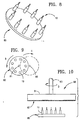
- FIGS. 8-10 illustrate a process of the present invention of refining the microdrill by forming a radius on the primary cutting edges.
- the microdrills 10 are placed vertically in a round carrier plate 80 which is then placed in a machine which rotates carrier plate 80 in a planetary motion.
- This planetary motion is illustrated schematically in FIG. 9, where it is shown that round carrier plate 80 rotates about its own axis 81 in direction B. Simultaneously, the carrier plate 80 is translated in direction C about center of rotation 82. While this planetary motion is occurring, a large rotating brush 90 is lowered into contact with the microdrills 10 as shown in FIG. 10.
- the large rotating brush 90 comprises a brush 91 having diamond paste applied to it on surface 92 or which has already been impregnated with diamond paste on surface 92.
- the brush is rotated in direction D about shaft 93.
- the rotating brush 90 is lowered into contact with the cutting tips 14 of the microdrills 10 while they are subject to the planetary motion as illustrated in FIG. 9.
- the abrasive action of the diamond paste produces a radius cutting edge 21, 61a on the primary cutting edges 20, 60 of microdrills 10 of controlled size and shape as described above with respect to the first and third embodiments of the present invention.
- the extent of the abrasive process may range from a slight polish to a more heavy hone.
- carrier plate 80 may be moved in a manner other than planetary motion while the rotating brush 90 is contacted with the microdrills 10.
- All three of the embodiments of the microdrill discussed above may be further modified by a surface decarburizing process.
- the surface decarburizing process can be done at a temperature from 600°C to 1100°C for 15 to 120 minutes.
- Surface decarburizing should take place in a controlled partial pressure of decarburizing gas, e.g., hydrogen, carbon dioxide, oxygen and other mixtures, with hydrogen being preferred, amid the general protective environment at the heat treating temperature.
- decarburizing can preferably be done at approximately 800°C for approximately 60 minutes in a mixture of argon and hydrogen.
- Cemented carbide microdrills are generally made by pressing and sintering a mixture of powders of one or more metallic carbides and a smaller amount of metal such as cobalt to serve as a binder.
- Cemented carbides have a very high hardness and strength which makes it an advantageous material to use in the drilling applications described above.
- cemented carbides are also brittle. This can lead to chipping, especially at the outer corners of the primary cutting edges.
- Surface decarburizing the microdrills increases resistance of the cemented carbide to wear as discussed above. Accordingly, the surface decarburizing process in combination with the refined primary cutting edges further increases the resistance to chipping and wear of the microdrills according to the present invention.
- FIG. 11 illustrates a distribution plot of drill life (number of holes drilled in fiberglass epoxy copper laminate) for the drill bits processed according to the present invention.
- the H curve illustrates a drill bit which has been honed only.
- the H & A curve illustrates a drill bit which has been honed and surface decarburized.
- the drill life for the H & A heat treated drill bits is approximately 2-5 times longer than for conventionally formed drill bits which have ground primary cutting edges.
- the surface decarburized cemented carbide microdrill includes a refined cutting edge to make it more resistant to chipping and wear.
- a cutting edge is most susceptible to wear and chipping at the sharp edge formed at the intersection of the flute and flank surface. Adding a radius, angular surface, or combination of the two to the surface decarburized cemented carbide microdrill eliminates the thinnest portion of the cutting edge. The resulting cutting edge is thereby stronger.
- the surface decarburizing process of the present invention could advantageously be used on other cemented carbide drill bits not limited to microdrills or drills having split points.
- the surface decarburizing process could be used on other types of cemented carbide cutting tools.
- the modified cutting edges of the present invention could also be used on other types of drill bits or rotating cutting tools generally.
Landscapes
- Engineering & Computer Science (AREA)
- Chemical & Material Sciences (AREA)
- Mechanical Engineering (AREA)
- Materials Engineering (AREA)
- Thermal Sciences (AREA)
- Crystallography & Structural Chemistry (AREA)
- Physics & Mathematics (AREA)
- Metallurgy (AREA)
- Organic Chemistry (AREA)
- Drilling Tools (AREA)
- Finish Polishing, Edge Sharpening, And Grinding By Specific Grinding Devices (AREA)
- Powder Metallurgy (AREA)
- Carbon And Carbon Compounds (AREA)
Applications Claiming Priority (9)
| Application Number | Priority Date | Filing Date | Title |
|---|---|---|---|
| US15180193A | 1993-11-15 | 1993-11-15 | |
| US15180093A | 1993-11-15 | 1993-11-15 | |
| US151801 | 1993-11-15 | ||
| US151800 | 1993-11-15 | ||
| US08/314,511 US5628837A (en) | 1993-11-15 | 1994-09-28 | Surface decarburization of a drill bit having a refined primary cutting edge |
| US314511 | 1994-09-28 | ||
| US314510 | 1994-09-28 | ||
| US08/314,510 US5609447A (en) | 1993-11-15 | 1994-09-28 | Surface decarburization of a drill bit |
| EP95901835A EP0690758B1 (de) | 1993-11-15 | 1994-11-10 | Oberflächen-entkohlung eines bohrer mit rafinierter primärschneidkante |
Related Parent Applications (1)
| Application Number | Title | Priority Date | Filing Date |
|---|---|---|---|
| EP95901835A Division EP0690758B1 (de) | 1993-11-15 | 1994-11-10 | Oberflächen-entkohlung eines bohrer mit rafinierter primärschneidkante |
Publications (1)
| Publication Number | Publication Date |
|---|---|
| EP1205563A1 true EP1205563A1 (de) | 2002-05-15 |
Family
ID=27495988
Family Applications (3)
| Application Number | Title | Priority Date | Filing Date |
|---|---|---|---|
| EP95901835A Expired - Lifetime EP0690758B1 (de) | 1993-11-15 | 1994-11-10 | Oberflächen-entkohlung eines bohrer mit rafinierter primärschneidkante |
| EP01204918A Withdrawn EP1205563A1 (de) | 1993-11-15 | 1994-11-10 | Oberflächen-Entkoklung eines Bohrer mit rafinierter Primärschneidkante |
| EP01204914A Withdrawn EP1203828A1 (de) | 1993-11-15 | 1994-11-10 | Oberflächen-Entkoklung eines Bohrer mit rafinierter Primärschneidkante |
Family Applications Before (1)
| Application Number | Title | Priority Date | Filing Date |
|---|---|---|---|
| EP95901835A Expired - Lifetime EP0690758B1 (de) | 1993-11-15 | 1994-11-10 | Oberflächen-entkohlung eines bohrer mit rafinierter primärschneidkante |
Family Applications After (1)
| Application Number | Title | Priority Date | Filing Date |
|---|---|---|---|
| EP01204914A Withdrawn EP1203828A1 (de) | 1993-11-15 | 1994-11-10 | Oberflächen-Entkoklung eines Bohrer mit rafinierter Primärschneidkante |
Country Status (8)
| Country | Link |
|---|---|
| EP (3) | EP0690758B1 (de) |
| JP (1) | JPH09500335A (de) |
| AT (1) | ATE219981T1 (de) |
| AU (1) | AU1092895A (de) |
| CA (1) | CA2153881A1 (de) |
| DE (1) | DE69430911T2 (de) |
| FI (1) | FI107452B (de) |
| WO (1) | WO1995013894A1 (de) |
Cited By (1)
| Publication number | Priority date | Publication date | Assignee | Title |
|---|---|---|---|---|
| EP4549065A4 (de) * | 2022-06-29 | 2025-09-17 | Sumitomo Electric Hardmetal Corp | Bohrer und schneidverfahren |
Families Citing this family (7)
| Publication number | Priority date | Publication date | Assignee | Title |
|---|---|---|---|---|
| US5944587A (en) * | 1997-07-29 | 1999-08-31 | The Gleason Works | Cutting edge rounding method |
| SE525336C2 (sv) * | 2002-05-17 | 2005-02-01 | Sandvik Ab | Borrverktyg för hålborrning i metalliska material |
| US7306411B2 (en) | 2002-09-03 | 2007-12-11 | Mitsubishi Materials Corporation | Drill with groove width variation along the drill and double margin with a thinning section at the tip |
| DE102005003496A1 (de) * | 2005-01-25 | 2006-07-27 | Gühring, Jörg, Dr. | Variabler Schneidkantenabzug für Bohrwerkzeuge |
| SE528917C2 (sv) * | 2005-07-05 | 2007-03-13 | Sandvik Intellectual Property | Spiralborr |
| DE102011086422B4 (de) * | 2011-11-15 | 2014-04-24 | Kennametal Inc. | Verfahren zur Herstellung eines Werkzeuges, sowie ein solches Werkzeug |
| JP6255925B2 (ja) * | 2013-11-12 | 2018-01-10 | 三菱マテリアル株式会社 | ドリル |
Citations (8)
| Publication number | Priority date | Publication date | Assignee | Title |
|---|---|---|---|---|
| DE2317447A1 (de) * | 1973-04-06 | 1974-10-24 | Sandvik Ab | Hartmetallkoerper |
| JPS59115150A (ja) * | 1982-12-08 | 1984-07-03 | Hitachi Choko Kk | 刃先強化エンドミルの製造法 |
| US4497874A (en) * | 1983-04-28 | 1985-02-05 | General Electric Company | Coated carbide cutting tool insert |
| US4898503A (en) * | 1988-07-05 | 1990-02-06 | Lockheed Corporation | Twist drill |
| JPH0320467A (ja) * | 1989-04-21 | 1991-01-29 | Toshiba Tungaloy Co Ltd | 密着性にすぐれたダイヤモンド被覆焼結体及びその製造方法 |
| US5009705A (en) * | 1989-12-28 | 1991-04-23 | Mitsubishi Metal Corporation | Microdrill bit |
| DE4124417A1 (de) * | 1990-08-31 | 1992-03-05 | Mas Vertriebsgesellschaft Fuer | Verfahren und maschine zum nachschleifen von hartmetallbohrern mit sonderschliff |
| JPH04300150A (ja) * | 1991-03-28 | 1992-10-23 | Mitsubishi Materials Corp | ドリルのホーニング加工方法 |
Family Cites Families (10)
| Publication number | Priority date | Publication date | Assignee | Title |
|---|---|---|---|---|
| NL6516429A (de) * | 1964-12-16 | 1966-06-17 | ||
| US4602900A (en) * | 1979-10-01 | 1986-07-29 | Arpaio Jr Jerry | Micro drill with modified drill point |
| JPS5771714A (en) * | 1980-10-23 | 1982-05-04 | Toshiba Corp | Drill for hard to cutting material |
| JPS6244304A (ja) * | 1985-08-20 | 1987-02-26 | Masao Kubota | ドリルのシンニング |
| EP0320881B2 (de) * | 1987-12-14 | 2003-10-22 | Mitsubishi Materials Corporation | Spiralbohrer |
| US5011342A (en) * | 1988-03-14 | 1991-04-30 | 501 Greenfield Industries, Inc. | Twist drill |
| JPH01242764A (ja) * | 1988-03-25 | 1989-09-27 | Sumitomo Electric Ind Ltd | 強靭サーメツト工具の製造方法 |
| JPH0215908A (ja) * | 1988-07-04 | 1990-01-19 | Toshiaki Hosoi | ドリル、ドリルの研摩方法および研摩装置 |
| SU1678532A1 (ru) * | 1989-04-11 | 1991-09-23 | Предприятие П/Я В-8534 | Способ термообработки инструмента из твердого сплава |
| US5097634A (en) * | 1989-12-08 | 1992-03-24 | Hulme Jack R | Tool grinder apparatus and method |
-
1994
- 1994-11-10 EP EP95901835A patent/EP0690758B1/de not_active Expired - Lifetime
- 1994-11-10 JP JP7514494A patent/JPH09500335A/ja not_active Ceased
- 1994-11-10 AU AU10928/95A patent/AU1092895A/en not_active Abandoned
- 1994-11-10 EP EP01204918A patent/EP1205563A1/de not_active Withdrawn
- 1994-11-10 CA CA002153881A patent/CA2153881A1/en not_active Abandoned
- 1994-11-10 AT AT95901835T patent/ATE219981T1/de not_active IP Right Cessation
- 1994-11-10 DE DE69430911T patent/DE69430911T2/de not_active Expired - Fee Related
- 1994-11-10 WO PCT/US1994/012929 patent/WO1995013894A1/en not_active Ceased
- 1994-11-10 EP EP01204914A patent/EP1203828A1/de not_active Withdrawn
-
1995
- 1995-07-13 FI FI953428A patent/FI107452B/fi active
Patent Citations (8)
| Publication number | Priority date | Publication date | Assignee | Title |
|---|---|---|---|---|
| DE2317447A1 (de) * | 1973-04-06 | 1974-10-24 | Sandvik Ab | Hartmetallkoerper |
| JPS59115150A (ja) * | 1982-12-08 | 1984-07-03 | Hitachi Choko Kk | 刃先強化エンドミルの製造法 |
| US4497874A (en) * | 1983-04-28 | 1985-02-05 | General Electric Company | Coated carbide cutting tool insert |
| US4898503A (en) * | 1988-07-05 | 1990-02-06 | Lockheed Corporation | Twist drill |
| JPH0320467A (ja) * | 1989-04-21 | 1991-01-29 | Toshiba Tungaloy Co Ltd | 密着性にすぐれたダイヤモンド被覆焼結体及びその製造方法 |
| US5009705A (en) * | 1989-12-28 | 1991-04-23 | Mitsubishi Metal Corporation | Microdrill bit |
| DE4124417A1 (de) * | 1990-08-31 | 1992-03-05 | Mas Vertriebsgesellschaft Fuer | Verfahren und maschine zum nachschleifen von hartmetallbohrern mit sonderschliff |
| JPH04300150A (ja) * | 1991-03-28 | 1992-10-23 | Mitsubishi Materials Corp | ドリルのホーニング加工方法 |
Non-Patent Citations (3)
| Title |
|---|
| PATENT ABSTRACTS OF JAPAN vol. 008, no. 234 (M - 334) 26 October 1984 (1984-10-26) * |
| PATENT ABSTRACTS OF JAPAN vol. 015, no. 137 (C - 0821) 5 April 1991 (1991-04-05) * |
| PATENT ABSTRACTS OF JAPAN vol. 017, no. 114 (M - 1377) 9 March 1993 (1993-03-09) * |
Cited By (1)
| Publication number | Priority date | Publication date | Assignee | Title |
|---|---|---|---|---|
| EP4549065A4 (de) * | 2022-06-29 | 2025-09-17 | Sumitomo Electric Hardmetal Corp | Bohrer und schneidverfahren |
Also Published As
| Publication number | Publication date |
|---|---|
| FI107452B (fi) | 2001-08-15 |
| AU1092895A (en) | 1995-06-06 |
| EP0690758B1 (de) | 2002-07-03 |
| FI953428A0 (fi) | 1995-07-13 |
| EP1203828A1 (de) | 2002-05-08 |
| DE69430911D1 (de) | 2002-08-08 |
| ATE219981T1 (de) | 2002-07-15 |
| EP0690758A4 (de) | 1998-02-04 |
| DE69430911T2 (de) | 2003-02-13 |
| FI953428L (fi) | 1995-08-28 |
| CA2153881A1 (en) | 1995-05-26 |
| JPH09500335A (ja) | 1997-01-14 |
| EP0690758A1 (de) | 1996-01-10 |
| WO1995013894A1 (en) | 1995-05-26 |
Similar Documents
| Publication | Publication Date | Title |
|---|---|---|
| US5628837A (en) | Surface decarburization of a drill bit having a refined primary cutting edge | |
| US5609447A (en) | Surface decarburization of a drill bit | |
| US4642003A (en) | Rotary cutting tool of cemented carbide | |
| US6585460B1 (en) | Drill having machine grindable cutting edge | |
| EP0560951B1 (de) | Verschleissfeste Werkzeuge | |
| US4802799A (en) | Drill bit | |
| US4713286A (en) | Printed circuit board drill and method of manufacture | |
| US4008976A (en) | Cutting tool and method for making same | |
| EP0132652B1 (de) | Verfahren zur Herstellung eines Bohrers für Leiterplatten | |
| KR20190126780A (ko) | 에너지 가공된 다결정 다이아몬드 컴팩트들 및 이에 관련된 방법 | |
| EP1418020B1 (de) | Bearbeitung von Flanken mit Hilfe von Superabrasiven | |
| EP0690758B1 (de) | Oberflächen-entkohlung eines bohrer mit rafinierter primärschneidkante | |
| EP3385014A1 (de) | Verfahren zur herstellung eines schneidwerkzeugs für die spanabhebende bearbeitung von werkstücken sowie schneidwerkzeug | |
| CN101678456A (zh) | 机加工基材的方法 | |
| US20220105574A1 (en) | Drilling tool | |
| JP2000043006A (ja) | 回転切削工具 | |
| JPS5943246B2 (ja) | 表面被覆超硬合金製ミニチユアドリル | |
| US6152660A (en) | Drilling tool for bores in solid material | |
| EP1322793A2 (de) | Abrasives und verschleissfestes material | |
| TW300922B (de) | ||
| JP3606742B2 (ja) | 台金にクリアランスを有するコアビット | |
| JPH1148016A (ja) | 小径ドリル | |
| JP2665565B2 (ja) | 木材平削り用刃物 | |
| KR102686399B1 (ko) | 가이드 패드팁의 접합구조를 갖는 버니싱 드릴 | |
| JP2003145287A (ja) | 硬脆性材料の加工方法 |
Legal Events
| Date | Code | Title | Description |
|---|---|---|---|
| PUAI | Public reference made under article 153(3) epc to a published international application that has entered the european phase |
Free format text: ORIGINAL CODE: 0009012 |
|
| 17P | Request for examination filed |
Effective date: 20020103 |
|
| AC | Divisional application: reference to earlier application |
Ref document number: 690758 Country of ref document: EP |
|
| AK | Designated contracting states |
Kind code of ref document: A1 Designated state(s): AT CH DE DK ES FR GB IT LI NL SE |
|
| AKX | Designation fees paid |
Designated state(s): AT CH DE DK ES FR GB IT LI NL SE |
|
| 17Q | First examination report despatched |
Effective date: 20030731 |
|
| STAA | Information on the status of an ep patent application or granted ep patent |
Free format text: STATUS: THE APPLICATION IS DEEMED TO BE WITHDRAWN |
|
| 18D | Application deemed to be withdrawn |
Effective date: 20031211 |