EP1207016B1 - Outil à impact - Google Patents
Outil à impact Download PDFInfo
- Publication number
- EP1207016B1 EP1207016B1 EP01127238A EP01127238A EP1207016B1 EP 1207016 B1 EP1207016 B1 EP 1207016B1 EP 01127238 A EP01127238 A EP 01127238A EP 01127238 A EP01127238 A EP 01127238A EP 1207016 B1 EP1207016 B1 EP 1207016B1
- Authority
- EP
- European Patent Office
- Prior art keywords
- fastener
- control device
- reached
- seated position
- workpiece
- Prior art date
- Legal status (The legal status is an assumption and is not a legal conclusion. Google has not performed a legal analysis and makes no representation as to the accuracy of the status listed.)
- Expired - Lifetime
Links
- 238000000034 method Methods 0.000 description 15
- 239000000758 substrate Substances 0.000 description 5
- 238000001514 detection method Methods 0.000 description 4
- 230000008569 process Effects 0.000 description 4
- 230000007246 mechanism Effects 0.000 description 3
- 230000009467 reduction Effects 0.000 description 3
- 230000008859 change Effects 0.000 description 2
- 239000000463 material Substances 0.000 description 2
- 230000001133 acceleration Effects 0.000 description 1
- 230000006835 compression Effects 0.000 description 1
- 238000007906 compression Methods 0.000 description 1
- 230000001419 dependent effect Effects 0.000 description 1
- 238000010586 diagram Methods 0.000 description 1
- 230000006870 function Effects 0.000 description 1
- 230000003116 impacting effect Effects 0.000 description 1
- 230000006698 induction Effects 0.000 description 1
- 230000004048 modification Effects 0.000 description 1
- 238000012986 modification Methods 0.000 description 1
Images


Classifications
-
- B—PERFORMING OPERATIONS; TRANSPORTING
- B25—HAND TOOLS; PORTABLE POWER-DRIVEN TOOLS; MANIPULATORS
- B25B—TOOLS OR BENCH DEVICES NOT OTHERWISE PROVIDED FOR, FOR FASTENING, CONNECTING, DISENGAGING OR HOLDING
- B25B21/00—Portable power-driven screw or nut setting or loosening tools; Attachments for drilling apparatus serving the same purpose
- B25B21/02—Portable power-driven screw or nut setting or loosening tools; Attachments for drilling apparatus serving the same purpose with means for imparting impact to screwdriver blade or nut socket
-
- B—PERFORMING OPERATIONS; TRANSPORTING
- B25—HAND TOOLS; PORTABLE POWER-DRIVEN TOOLS; MANIPULATORS
- B25B—TOOLS OR BENCH DEVICES NOT OTHERWISE PROVIDED FOR, FOR FASTENING, CONNECTING, DISENGAGING OR HOLDING
- B25B23/00—Details of, or accessories for, spanners, wrenches, screwdrivers
- B25B23/14—Arrangement of torque limiters or torque indicators in wrenches or screwdrivers
- B25B23/1405—Arrangement of torque limiters or torque indicators in wrenches or screwdrivers for impact wrenches or screwdrivers
Definitions
- the present invention relates to power tools and more particularly, relates to power tools, such as impact wrenches and impact screwdrivers, having a drive source that is controlled by a pre-set operating program (operating mode).
- Known impact power tools have a drive source that is controlled by a pre-set or predetermined operating program (operating mode) in order to facilitate the tightening operation and to provide uniform work quality.
- operating program operating program
- known impact wrenches and impact screwdrivers can be operated according to such operating programs.
- known impact tightening tools generally include a drive source, such as an electric motor or a pneumatic motor, that rotates a hammer in order to strike an anvil and generate an elevated torque.
- This elevated torque may be utilized to securely tighten a fastener, such as a screw, a nut or a bolt.
- a fastener such as a screw, a nut or a bolt.
- the hammer is allowed to slip and freely rotate with respect to the anvil when a predetermined amount of torque is exerted.
- the fastener can be driven with a relatively light load until a head portion of the fastener contacts the workpiece (i.e., before the fastener becomes seated against workpiece), because the hammer will continuously rotate the anvil in order to continuously tighten the fastener using a relatively low torque.
- the fastener is driven further and the hammer exerts more than a predetermined amount of force against anvil, because the head of the fastener has contacted the workpiece (i.e., after the fastener has become seated against the workpiece), the hammer will begin to slip and rotate freely. Therefore, the hammer will impact the anvil after rotating by a predetermined angle. By the repetition of the slipping and impacting action, the anvil will rotate a small amount each time the hammer impacts the anvil and the fastener can be tightened to an appropriate torque.
- the tightening torque may be determined based upon the number of times that hammer impacts or strikes the anvil. Therefore, if the number of impacts between the hammer and anvil is too high, the tightening torque applied to the fastener will be too great and may possibly damage the fastener.
- a known technique detects the number of impacts between the hammer and anvil, and automatically stops the drive source of the hammer when a pre-determined number of impacts have been detected (i.e., the tightening torque is determined by the number of impacts).
- a sensor is utilized to detect impacts between the hammer and anvil and a microprocessor counts the number of impacts. When the number of counted impacts reaches a preset number, the drive source is automatically stopped to prevent the fastener from being over-tightened.
- the drive source can be automatically stopped after a predetermined time interval or period has elapsed after the detection of the first impact of the hammer striking the anvil. Therefore, application of excessive torque is avoided and damage to the fastener can be prevented.
- US-A-5 715 894 discloses an impact screw-tightening apparatus including a torque detector for detecting a torque applied to the main shaft of the impact torque generator. It is decided by each single impact as to whether the bearing surface of a bolt to be tightened is in contact with the object or not. This decision is based on the determination whether a free running time is smaller than or equal to a free running time threshold.
- the free running time is the time period between the first and the second torque pulse among many torque pulses generated at one impact and sensed by the torque detector.
- the first torque pulse is a torque wave form when the torque applied e.g. to a blot or nut increases and reaches the maximum static-friction torque so that the bolt or nut starts to rotate.
- the second torque pulse is a torque waveform, when the rotating bolt or nut gradually slows down and stops to rotate by dynamical friction.
- the free running time i.e. the time period between the first torque pulse and the second torque pulse, a bolt or nut is rotating in the state of free running.
- the free-running time becomes short suddenly when the bolt or nut comes in contact with the tightened object and the free-running time is no longer observed after bolt or nut has reached a seated position.
- EP 0 271 903 A2 discloses a method of tightening screw-threaded fasteners for producing workpiece joints by using a power driven rotary tightening tool the snug point of the fastener is determined by detecting a speed reduction of rotatable parts of the tightening tool when the snug point is reached.
- An apparatus for tightening the screw-threaded fastener comprises a power-driven rotary tightening tool including an induction motor, an inverter control circuit and a further control circuit capable of determining a reduction in speed of the motor indicative of the snug point, said further control circuit including a proximity detector responsive to the passage of a rotating metallic part of the motor or of a metallic part driven by the motor.
- a solution of this object is achieved with a power tool according to claim 1.
- the control device determines whether the impact generating means has begun to operate and generate the elevated torque before the fastener has reached a seated position against the work piece or after the fastener has reached the seated position against the work piece by utilising the time interval between consecutive impacts.
- This time interval can be measured by evaluating the output signal of a simple sensor, e. g. a sound receiver according to claim 2.
- the type of sensor that can be utilized with the present teachings is not particularly limited and may be any type of sensor capable of detecting impacts between the hammer and anvil.
- the present teachings contemplate the use of accelerometers, which detect the acceleration of the hammer, proximity sensors, which detect the position of the hammer, and/or sound sensors (e.g., condenser microphones, piezoelectric materials, etc.), which detect impact sounds generated by the hammer striking the anvil (or oil pulses generated by an oil pulse unit).
- power tools are taught for tightening a fastener and include a drive source, such as a motor. Further, the power tool includes means for generating an elevated torque operably coupled to the drive source, which means may include a hammer and anvil or may include an oil pulse unit. A sensor detects when the means for generating an elevated torque has begun to operate and generate the elevated torque. A wide variety of sensors may be utilized for this purpose.
- a control device such as a microprocessor or microcomputer, communicates with the sensor and the drive source. Further, the sensor communicate signals to the control device when the means for generating an elevated torque has begun to operate and generate the elevated torque. For example, the control device determines whether the means for generating an elevated torque has begun to operate and generate the elevated torque either (1) before the fastener has reached a seated position against a workpiece or (2) after the fastener has reached the seated position against the workpiece. Thereafter, the control device controls the operation the drive source based upon signals generated by the sensor only after the fastener has reached the seated position against the workpiece. For example, the control device may effectively ignore signals that are determined to have occurred before the fastener has become seated against the workpiece.
- the control device starts a timer when the control device determines that the means for generating an elevated torque has begun to operate and generates an elevated torque after the fastener has reached the seated position against the workpiece. Thereafter, the control device preferably stops the drive source when the timer reaches a pre-selected or pre-determined amount (or period) of time. Further, the control device re-sets the timer to zero when the control device determines that the means for generating an elevated torque has begun to operate before the fastener has reached the seated position against the workpiece.
- the control device starts a counter to count the number of signals generated by the sensor after the fastener has reached the seated position. Thereafter, the control device stops the drive source when the pre-determined number of signals have been counted.
- the pre-determined number of signals preferably corresponds to a desired amount of torque that the operator would like to apply to the fastener.
- the control device may re-set the counter to zero when the control device determines that the means for generating an elevated torque has begun to operate before the fastener has reached the seated position against the workpiece.
- the control device determines that the fastener has reached the seated position against the workpiece by determining whether a first signal and a subsequent signal generated by the sensor occur within a predetermined interval (or period) of time. If the time between the detected signals is greater than the pre-determined interval (or period) of time, the control device preferably determines that the first signal occurred before the fastener has reached the seated position against the workpiece.
- control device may control the drive source according to a selected or a pre-determined operating mode.
- means may be provided for setting at least one operating mode coupled to the control device.
- Such setting means may be, e.g., dial switches (or dial selectors) or a remote control device (e.g., a device that communicates instructions to the control device by radio waves, infrared waves or other wavelengths).
- a switch may be provided for changing the operating mode set by the setting means to the predetermined operating mode. Thereafter, the control device may drive the drive source in the predetermined operating mode when the switch is operated according to a predetermined condition. Further, the control device may drive the drive source in the operating mode set by the setting means when the switch is not operated according to the predetermined condition. In addition, the control device may automatically return to the operating mode set by the setting means after completing driving the drive source in the predetermined operating mode selected by the switch.
- the switch may be a startup switch (e.g., a trigger switch) that energizes the drive source.
- the control device may select the predetermined operating mode when the start up switch is switched from the ON position to the OFF position in a predetermined condition, and the start up switch is then switched back to the ON position again within a predetermined time period.
- the control device may select the operating mode set by the setting device when the start up switch is not switched back to the ON position within the pre-determined time period after having been switched from the ON position to the OFF position.
- control device may stop the drive source when impact sounds (e.g., the hammer striking the anvil or the oil pulse unit begins to generate an elevated torque) are repeatedly detected by the sensor within a predetermined time interval.
- impact sounds e.g., the hammer striking the anvil or the oil pulse unit begins to generate an elevated torque
- control device will not stop the drive source unless a preset time has elapsed since detection of the repeated impacts within the predetermined time interval.
- FIG. 1 shows a representative embodiment of the present teachings.
- impact wrench 1 includes motor 22 that is disposed within housing 3.
- Gear 19 is disposed on output shaft 20, which is coupled to motor 22.
- Gear 19 engages a plurality of planet gears 12 that are rotatably mounted on pin 14.
- Internal gear 16 is disposed within internal gear case 18 and engages planet gears 12. The gears may reduce the driving speed of a tool bit (not shown).
- pin 14 may be fixedly attached to a spindle 8, which is rotatably mounted within housing 3.
- Spindle 8 is rotatably driven by motor 22 using a reduction gear mechanism, which comprises gears 12, 16, and hammer 4 is rotatably mounted on the spindle 8.
- a cam mechanism having a plurality of recesses 8a and bearings 6, which bearings 6 are disposed within recesses 8a, is interposed between hammer 4 and spindle 8.
- Recesses 8a are formed within spindle 8 in a V-shape and thus extend obliquely relative to the longitudinal axis of spindle 8.
- the cam mechanism permits hammer 4 to move by a predetermined distance along spindle 8 in the longitudinal direction.
- Compression spring 10 is interposed between hammer 4 and spindle 8 via bearing 51 and washer 49 so as to normally bias hammer 4 in the rightward direction of FIG. 1 .
- Anvil 2 is rotatably mounted on the forward end of housing 3 and cooperates with hammer 4 to generate a tightening torque.
- Forward portion 2a of anvil 2 has a polygonal cross-section that is adapted to mount the tool bit (not shown). The tool bit then engages the fastening device (fastener) in order to drive the fastening device into the workpiece.
- the rear end of anvil 2 preferably has two protrusions 2b, 2c that radially extend from anvil 2.
- the forward portion of hammer 4 also preferably has two protrusions 4b, 4c that radially extend from hammer 4. Protrusions 2b, 2c and protrusions 4b, 4c are adapted to abut each other.
- Figure 2 shows a view looking into the handle from the direction indicated by line II in Figure 1 (i.e., from the bottom of the impact wrench 1), after battery pack 122 has been removed from impact wrench 1.
- main switch 48 for starting motor 22 and motor rotation direction switch 24 for switching the direction of rotation of motor 22 are installed on handle 3a.
- Main switch 48 is preferably a trigger switch.
- setting device 34 is installed on the bottom of handle 3a.
- Setting device 34 may include, e.g., first setting dial 33 and second setting dial 35, as shown in Figure 2 .
- a scale of numerals 0 through 9 and a scale of letters A through F may be provided on first setting dial 33.
- a scale of numerals 0 through 9 may be provided on second setting dial 35.
- the time period may be selected using the numerical value "X" set using first dial 33 and the numerical value "Y" set using second dial 35.
- the time period T may be determined, e.g., by the equation: [(X x 10) + Y] x 0.02 seconds.
- first setting dial 33 and second setting dial 35 are both set to "0,” the manual operating mode will be selected and motor 22 will be continuously driven as long as main switch 48 is switched to the ON position, regardless of whether an impact has been detected or not.
- setting device 34 also can be utilized to set a desired tightening torque value. Therefore, control device can select an appropriate method for stopping motor 22 when the desired amount of torque has been applied to the fastener.
- control device instead of stopping motor 22 after a predetermined period of time has elapsed, the control device also could stop motor 22 after a predetermined number of impacts have been detected. Because the number of impacts also generally corresponds to the amount of torque applied to the fastener, this counting technique can also be advantageously utilized with the present teachings.
- each dial 33 and 35 can be changed only when battery pack 122 is removed from handle portion 3a, which will prevent accidental changes in the values set on the dials 33 and 35.
- contact element 42 is disposed on the bottom of handle portion 3a so that contact element 42 will contact the corresponding electrical contact (not shown) of battery pack 122.
- control substrate 36 may be mounted within the bottom of handle portion 3a, as shown in Figure 1 .
- Microcomputer 38, switching circuit 114 and other electronic parts can be mounted on control substrate 36.
- Control substrate 36 may be, e.g., a printed circuit board.
- a sound receiver 30 e.g., a piezoelectric buzzer
- a sound receiver 30 that is capable of detecting impact sounds generated when hammer 4 strikes anvil 2 also can be mounted on control substrate 36.
- a representative control circuit (control device) for operating impact wrench 1 is shown in Figure 3 .
- the control circuit includes sound receiver 30 and microcomputer 38 mounted on control substrate 36.
- Microcomputer 38 may preferably include, e.g., central processing unit (CPU) 110, read only memory (ROM) 118, random access memory (RAM) 120 and input/output port (I / O) 108, all of which may be connected as shown in Figure 3 and may be, e.g., integrated onto a single chip.
- ROM 118 may preferably store one or more control programs for operating impact wrench 1.
- ROM 118 may include a program for stopping the motor 22 after a certain number of impacts (between hammer 4 and anvil 2) have been detected by sound receiver 30.
- Sound receiver 30 is preferably coupled via filter 102 to one terminal of comparator 104.
- Voltage V3 from reference voltage generator 112 is input to the other terminal of comparator 104.
- the output voltage from comparator 104 is coupled to microcomputer 38.
- the output voltage preferably represents impacts (i.e., between hammer 4 and anvil 2) detected by sound receiver 30.
- Battery pack 122 is coupled to microcomputer 38 and is further coupled to motor 22 via main switch 48, motor rotation direction switch 24 and switch 40.
- Switching circuit 114 couples switch 40 to microcomputer 38.
- switch 40 is turned ON and OFF by an output signal from microcomputer 38.
- microcomputer 38 is also coupled to setting device 34, which includes dials 33 and 35.
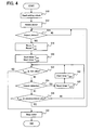
- Figure 4 shows a representative method for operating microcomputer 38 in order to tighten a fastener (fastening device) using impact wrench 1. That is, Figure 4 is a flowchart of a portion of the process or program executed by microcomputer 38 during a tightening operation.
- a fastener e.g., a nut or bolt
- main switch 48 is switched or actuated to the ON position and microcomputer 38 will control the rotation of motor 22 in accordance with the operating mode currently being utilized.
- microcomputer 38 when main switch 48 is switched to the ON position, microcomputer 38 first reads the setting values (i.e., numerical values "XY") currently set on setting device 34 (step S10). As noted above, the time period between detection of an impact sound and stopping the motor 22 can be set utilizing the numerical value "X" set on the first setting dial 33 and the numerical value "Y” set on the second setting dial 35. Therefore, when main switch 48 is switched to the ON position, microcomputer 38 first reads the numerical value "XY" set on setting device 34, and calculates the interval of time (or the number of counted impacts) for stopping the motor 22 after detection of a first impact sound. Thereafter, microcomputer 38 outputs a signal to switch 40 via switching circuit 114 in order to start the rotation of motor 22 (step S12). As a result, motor 22 will start rotating and the fastener will be tightened in the workpiece.
- the setting values i.e., numerical values "XY”
- step S10 the time period between detection of an impact sound and stopping the motor 22 can
- step S14 microcomputer 38 determines whether hammer 4 has impacted or struck anvil 2 (i.e., whether an impact sound has been detected). For example, microcomputer 38 determines whether a pulse wave has been output the comparator 104. If an impact between hammer 4 and anvil 2 has not been detected (NO in step S14), step S14 is repeated until an impact between hammer 4 and anvil 2 is detected. That is, microcomputer 38 assumes a standby status with respect to this operation until the first impact between hammer 4 and anvil 2 is detected.
- T auto represents the period of period that motor 22 will be permitted to rotate until it is automatically stopped (naturally, if T auto has not been reset in the meantime).
- T width represents a time period for determining whether an impact detected in step S 14 is an impact before or after the fastener has reached the seated position.
- microcomputer 38 After starting the two timers in step S20, microcomputer 38 proceeds to step S22 and determines whether automatic stop timer T auto has exceeded the time period set using setting device 34 (i.e., the time T set calculated based upon the numerical value "XY" that was read in step S10). If automatic stop timer T auto has exceeded the set value (YES in step S22), motor 22 is stopped (step S32), based upon the assumption that the fastener has been sufficiently tightened to the appropriate torque. More specifically, microcomputer 38 preferably turns OFF switch 40 by stopping the signal being output to switch 40.
- microcomputer 38 determines whether a new impact between the hammer 4 and anvil 2 has been detected (step S24). If a new impact between the hammer 4 and anvil 2 has been detected (YES in step S24), timer T width is reset (step S28) and re-started (step S30). Then, microcomputer 38 returns to step S22.
- the set value (T auto ) in step S22 may be preferably about 1.0 second.
- the predetermined value (T width ) in step S26 is preferably much shorter than the set value (T auto ) (e.g., about 0.1 second).
- microcomputer 38 determines whether timer T width has exceeded the predetermined value (step S26). That is, the predetermined value is compared to the time actually counted by timer T width .
- the predetermined value in step S26 is preferably set to be several times of the average interval between impacts after the fastener has reached the seated position.
- the predetermined value may be set to 0.1 second, which is about 5 times the average interval (i.e., 0.02 second) between impacts after the fastener has reach the seated position. Therefore, if timer T width has exceeded the predetermined value (e.g., about 0.1 second), because a new impact has not been detected after the predetermined time has elapsed after the first impact was detected (YES in step S26), the impact detected in step S14 is determined to be an impact before the fastener has reached the seated position. Thus, the process will return to step S14 in this case.
- the predetermined value of step 26, which is compared to the time counted by timer T width can be suitably adjusted according to the specifications (diameter, material, etc.) of the fastener being tightened.
- step S26 If timer T width has not yet exceeded the predetermined value (NO in step S26), the process returns to step S22.
- a first timer (e.g., T width ) is reset to zero and then started. If the next impact is not detected within the predetermined time of step S26, microcomputer 38 determines that the first detected impact occurred before the fastener reached the seated position and the process returns to step S14. Thereafter, when the next impact is detected, both the first and second timers (e.g., T width and T auto ) are reset and started again. Therefore, motor 22 will not be stopped because the second timer (i.e., T auto ) has exceeded the set value of step S22.
- T width the first and second timer
- motor 22 is preferably automatically stopped after expiration of the set value (e.g., about 1 second).
- the set value e.g., about 1 second.
- timer T auto is not reset after an impact is detected that is determined to have occurred after the fastener reached the seated position.
- the set value will provide sufficient time for the fastener to be tightened to the desired torque. Consequently, motor 22 of impact wrench 1 will be driven for a predetermined time (time set by setting device 34) after the fastener has reached the seated position.
- the second timer i.e., T auto
- T auto the second timer
- the set value in step S22 can be changed by the operator or another person (e.g., using setting device 34) in order to change the amount of torque applied to the fastener.
- motor 22 was stopped after a predetermined time had elapsed after the impact between the hammer 4 and anvil 2 is detected, motor 22 also could be stopped based upon a certain number of detected impacts.
- Various tightening tools utilize an "auto-stop" function that stops the rotation of the motor 22 when the total number of impacts between hammer 4 and anvil 2 reaches a preset or predetermined number.
- the present teachings can be suitable applied to this type of tightening tools. For example, if an impact is detected and the microcomputer determines that the impact occurred before the fastener reached the seated position, the impact could be nullified (decrement the count by 1), or it could be utilized to reset the current count.
- the representative embodiment activated the auto-stop timer after detecting an impact and reset the auto-stop timer if the control device determined that the detected impact occurred before the fastener has reached the seated position.
- the auto-stop timer also could be activated after a detected impact is determined to have occurred after the fastener has reached the seated position.
- the motor could be driven for a duration of time - calculated by subtracting the amount of time, which is required to determine whether the impact has occurred after the fastener has reached the seated position, from the preset time.
Landscapes
- Engineering & Computer Science (AREA)
- Mechanical Engineering (AREA)
- Details Of Spanners, Wrenches, And Screw Drivers And Accessories (AREA)
- Portable Nailing Machines And Staplers (AREA)
- Percussive Tools And Related Accessories (AREA)
Claims (7)
- Outil motorisé (1) pour serrer une pièce de fixation,
comprenant:une source d'entraînement (22),des moyens (2, 4) destinés à générer des impacts pour augmenter un couple agissant sur la pièce de fixation, lesquels moyens générateurs d'impacts sont opérationnellement couplés à la source d'entraînement,un capteur (30) détectant le fonctionnement des moyens générateurs d'impact etun dispositif de contrôle (38) en communication avec la source d'entraînement qui contrôle uniquement le fonctionnement de la source d'entraînement après que la pièce de fixation a atteint la position assise contre la pièce d'oeuvre, dans lequel le dispositif de contrôle (38) détermine si le moyen générateur d'impacts a commencé à fonctionner et à générer le couple élevé soit (1) avant que la pièce de fixation ait atteint une position calée contre la pièce d'oeuvre soit (2) après que la pièce de fixation a atteint la position calée contre la pièce d'oeuvre en utilisant des signaux générés par ledit capteur,caractérisé en ce queledit capteur (30) génère des signaux qui représentent des impacts générés par le moyen générateur d'impact (2, 4) et ledit dispositif de contrôle (38) utilise l'intervalle de temps entre des impacts consécutifs pour déterminer si le moyen générateur d'impact a commencé à fonctionner et à générer le couple élevé soit (1) avant que la pièce de fixation ait atteint une position calée contre la pièce d'oeuvre soit (2) après que la pièce de fixation a atteint la position calée contre la pièce d'oeuvre. - Outil motorisé (1) tel que revendiqué dans la revendication 1, caractérisé en ce que ledit capteur comprend un récepteur de sons (30).
- Outil motorisé (1) tel que revendiqué dans la revendication 1 ou 2, dans lequel le moyen destiné à générer un couple élevé comprend:une enclume (2) etun marteau (4) couplé à la source d'entraînement (22), le marteau étant adapté pour frapper l'enclume pour faire ainsi tourner l'enclume et générer le couple élevé.
- Outil motorisé (1) tel que revendiqué dans la revendication 1 ou 2, dans lequel le moyen destiné à générer un couple élevé comprend une unité de type hydraulique.
- Outil motorisé (1) tel que revendiqué dans l'une quelconque des revendications 1 à 4, dans lequel le dispositif de contrôle (38) déclenche une minuterie quand le dispositif de contrôle détermine que le moyen (2, 4) destiné à générer un couple élevé a commencé à fonctionner et à générer un couple élevé après que la pièce de fixation a atteint la position calée contre la pièce d'oeuvre, et arrête la source d'entraînement (22) quand la minuterie atteint une quantité prédéterminée de temps, et dans lequel le dispositif de contrôle remet la minuterie à zéro quand le dispositif de contrôle détermine que le moyen destiné à générer un couple élevé a commencé à fonctionner avant que la pièce de fixation ait atteint la position calée contre la pièce d'oeuvre.
- Outil motorisé (1) tel que revendiqué dans l'une quelconque des revendications 1 à 4, dans lequel le dispositif de contrôle (38) commence à compter le nombre de signaux générés par le capteur (30) après que la pièce de fixation a atteint la position calée et arrête la source d'entraînement quand le nombre prédéterminé de signaux a été compté, et dans lequel le dispositif de contrôle remet le compteur à zéro quand le dispositif de contrôle détermine que le moyen destiné à générer un couple élevé a commencé à fonctionner avant que la pièce de fixation ait atteint la position calée contre la pièce d'oeuvre.
- Outil motorisé (1) tel que revendiqué dans l'une quelconque des revendications précédentes, dans lequel le dispositif de contrôle (38) détermine que la pièce de fixation a atteint la position calée contre la pièce d'oeuvre en déterminant si un premier signal et un signal subséquent générés par le capteur sont survenus dans un intervalle de temps prédéterminé, dans lequel si le temps entre les signaux est plus long que l'intervalle de temps prédéterminé, le dispositif de contrôle détermine que le premier signal est survenu avant que la pièce de fixation ait atteint la position calée contre la pièce d'oeuvre.
Priority Applications (1)
| Application Number | Priority Date | Filing Date | Title |
|---|---|---|---|
| EP07019141A EP1867438A3 (fr) | 2000-11-17 | 2001-11-16 | Outil électrique d'impact |
Applications Claiming Priority (4)
| Application Number | Priority Date | Filing Date | Title |
|---|---|---|---|
| JP2000350438 | 2000-11-17 | ||
| JP2000350438A JP3734700B2 (ja) | 2000-11-17 | 2000-11-17 | 打撃締付工具 |
| JP2000356335 | 2000-11-22 | ||
| JP2000356335A JP3883804B2 (ja) | 2000-11-22 | 2000-11-22 | 動作モード切替機能を備える電動工具 |
Related Child Applications (1)
| Application Number | Title | Priority Date | Filing Date |
|---|---|---|---|
| EP07019141A Division EP1867438A3 (fr) | 2000-11-17 | 2001-11-16 | Outil électrique d'impact |
Publications (3)
| Publication Number | Publication Date |
|---|---|
| EP1207016A2 EP1207016A2 (fr) | 2002-05-22 |
| EP1207016A3 EP1207016A3 (fr) | 2004-02-11 |
| EP1207016B1 true EP1207016B1 (fr) | 2009-01-07 |
Family
ID=26604131
Family Applications (2)
| Application Number | Title | Priority Date | Filing Date |
|---|---|---|---|
| EP07019141A Withdrawn EP1867438A3 (fr) | 2000-11-17 | 2001-11-16 | Outil électrique d'impact |
| EP01127238A Expired - Lifetime EP1207016B1 (fr) | 2000-11-17 | 2001-11-16 | Outil à impact |
Family Applications Before (1)
| Application Number | Title | Priority Date | Filing Date |
|---|---|---|---|
| EP07019141A Withdrawn EP1867438A3 (fr) | 2000-11-17 | 2001-11-16 | Outil électrique d'impact |
Country Status (3)
| Country | Link |
|---|---|
| US (1) | US6598684B2 (fr) |
| EP (2) | EP1867438A3 (fr) |
| DE (1) | DE60137299D1 (fr) |
Cited By (6)
| Publication number | Priority date | Publication date | Assignee | Title |
|---|---|---|---|---|
| US10052733B2 (en) | 2015-06-05 | 2018-08-21 | Ingersoll-Rand Company | Lighting systems for power tools |
| US10418879B2 (en) | 2015-06-05 | 2019-09-17 | Ingersoll-Rand Company | Power tool user interfaces |
| US10615670B2 (en) | 2015-06-05 | 2020-04-07 | Ingersoll-Rand Industrial U.S., Inc. | Power tool user interfaces |
| US10668614B2 (en) | 2015-06-05 | 2020-06-02 | Ingersoll-Rand Industrial U.S., Inc. | Impact tools with ring gear alignment features |
| US11260517B2 (en) | 2015-06-05 | 2022-03-01 | Ingersoll-Rand Industrial U.S., Inc. | Power tool housings |
| US11491616B2 (en) | 2015-06-05 | 2022-11-08 | Ingersoll-Rand Industrial U.S., Inc. | Power tools with user-selectable operational modes |
Families Citing this family (101)
| Publication number | Priority date | Publication date | Assignee | Title |
|---|---|---|---|---|
| AUPP247798A0 (en) | 1998-03-18 | 1998-04-23 | Rudduck, Dickory | Fixing and release systems |
| US6536536B1 (en) * | 1999-04-29 | 2003-03-25 | Stephen F. Gass | Power tools |
| DE60128418T2 (de) * | 2000-03-16 | 2008-01-17 | Makita Corp., Anjo | Angetriebenes Schlagwerkzeug mit Mitteln zum Ermitteln des Schlaggeräusches |
| AUPQ861300A0 (en) * | 2000-07-06 | 2000-08-03 | Telezygology Pty Limited | Mulit-function tool |
| JP3886818B2 (ja) | 2002-02-07 | 2007-02-28 | 株式会社マキタ | 締付工具 |
| US7600301B2 (en) * | 2002-06-19 | 2009-10-13 | Telezygology, Inc. | Fixing and release systems and fastener networks |
| DE10303006B4 (de) * | 2003-01-27 | 2019-01-03 | Hilti Aktiengesellschaft | Handgeführtes Arbeitsgerät |
| DE602004032279D1 (de) * | 2003-02-05 | 2011-06-01 | Makita Corp | Kraftgetriebenes Werkzeug mit Drehmomentbegrenzung unter ausschliesslicher Benutzung eines Drehwinkelsensors |
| US7062979B2 (en) * | 2003-03-19 | 2006-06-20 | The Boeing Company | Tool and associated methods for controllably applying torque to a fastener |
| KR100496658B1 (ko) * | 2003-03-31 | 2005-06-22 | 주식회사 세한전동 | 조립 검증 기능의 카운터를 구비한 전동 드라이버 시스템 |
| USD487219S1 (en) | 2003-04-08 | 2004-03-02 | Snap-On Technologies, Corp | Hand-held tool |
| USD484384S1 (en) | 2003-04-24 | 2003-12-30 | Snap-On Technologies, Inc. | Cordless power tool |
| JP4093145B2 (ja) * | 2003-08-26 | 2008-06-04 | 松下電工株式会社 | 締付け工具 |
| JP2005066785A (ja) * | 2003-08-26 | 2005-03-17 | Matsushita Electric Works Ltd | 電動工具 |
| JP3903976B2 (ja) * | 2003-10-14 | 2007-04-11 | 松下電工株式会社 | 締付け工具 |
| JP2005144564A (ja) * | 2003-11-11 | 2005-06-09 | Matsushita Electric Works Ltd | 可搬式電動工具 |
| DE10360165A1 (de) * | 2003-12-20 | 2005-09-29 | C. & E. Fein Gmbh | Elektrowerkzeug |
| US20060102367A1 (en) * | 2004-02-04 | 2006-05-18 | Etter Mark A | Pneumatically powered rotary tool having linear forward and reverse switch |
| JP4906236B2 (ja) * | 2004-03-12 | 2012-03-28 | 株式会社マキタ | 締付工具 |
| DE102005015900B4 (de) | 2004-04-10 | 2020-07-09 | Marquardt Gmbh | Elektrowerkzeug, insbesondere Schlagschrauber |
| JP4211676B2 (ja) * | 2004-05-12 | 2009-01-21 | パナソニック電工株式会社 | インパクト回転工具 |
| JP4400303B2 (ja) * | 2004-05-12 | 2010-01-20 | パナソニック電工株式会社 | インパクト回転工具 |
| JP4211675B2 (ja) * | 2004-05-12 | 2009-01-21 | パナソニック電工株式会社 | インパクト回転工具 |
| JP4211744B2 (ja) * | 2005-02-23 | 2009-01-21 | パナソニック電工株式会社 | インパクト締付け工具 |
| US20060225904A1 (en) * | 2005-04-12 | 2006-10-12 | Interflow Corp. | Power tool that can interrupt the electric power automatically |
| US20060237205A1 (en) * | 2005-04-21 | 2006-10-26 | Eastway Fair Company Limited | Mode selector mechanism for an impact driver |
| USD560108S1 (en) | 2005-07-19 | 2008-01-22 | Milwaukee Electric Tool Corporation | Power tool, such as a nailer |
| CN101267906B (zh) * | 2005-08-29 | 2010-11-03 | 迪美科技控股有限公司 | 电动工具 |
| US7942211B2 (en) * | 2005-08-29 | 2011-05-17 | Demain Technology, Pty Ltd | Power tool |
| FR2892042A1 (fr) * | 2005-10-14 | 2007-04-20 | Prospection & Inventions | Outil a actionnement manuel, a fonctionnement a gaz et a horloge temps reel. |
| USD536591S1 (en) | 2006-01-19 | 2007-02-13 | Snap-On Incorporated | Cordless drill |
| USD535536S1 (en) | 2006-01-19 | 2007-01-23 | Snap-On Incorporated | Cordless impact tool |
| US8091650B2 (en) * | 2006-03-23 | 2012-01-10 | Demain Technology Pty Ltd. | Power tool guard |
| PL2035238T3 (pl) * | 2006-05-31 | 2013-08-30 | Technomark | Urządzenie do znakowania wykrywające uderzenia i odpowiedni sposób |
| JP4375362B2 (ja) * | 2006-06-29 | 2009-12-02 | パナソニック電工株式会社 | 電動工具用スイッチ装置 |
| US20080276764A1 (en) * | 2007-05-09 | 2008-11-13 | Chih-Ching Hsieh | Spanner with tension setting assembly |
| US20090173194A1 (en) * | 2008-01-09 | 2009-07-09 | Jui Yu Chen | Impact wrench structure |
| JP2009166146A (ja) * | 2008-01-11 | 2009-07-30 | Makita Corp | 結束工具 |
| DE102008015005A1 (de) * | 2008-03-19 | 2009-09-24 | Mtu Aero Engines Gmbh | Spannfutter-integriertes Kraftmesssystem |
| JP5348608B2 (ja) * | 2008-06-30 | 2013-11-20 | 日立工機株式会社 | 電動式打込機 |
| US8269612B2 (en) | 2008-07-10 | 2012-09-18 | Black & Decker Inc. | Communication protocol for remotely controlled laser devices |
| US9061392B2 (en) * | 2008-07-25 | 2015-06-23 | Sylvain Forgues | Controlled electro-pneumatic power tools and interactive consumable |
| EP2305430A1 (fr) * | 2009-09-30 | 2011-04-06 | Hitachi Koki CO., LTD. | Outil de frappe rotatif |
| JP5441003B2 (ja) * | 2009-10-01 | 2014-03-12 | 日立工機株式会社 | 回転打撃工具 |
| JP5600955B2 (ja) * | 2010-02-11 | 2014-10-08 | 日立工機株式会社 | インパクト工具 |
| DE102010002702A1 (de) * | 2010-03-09 | 2011-09-15 | Robert Bosch Gmbh | Elektrogerät, insbesondere Elektrohandwerkzeug |
| US9950417B2 (en) * | 2010-03-31 | 2018-04-24 | Hitachi Koki Co., Ltd. | Power tool |
| US9318932B2 (en) | 2010-06-14 | 2016-04-19 | Black & Decker Inc. | Control unit for a power tool |
| JP2012076160A (ja) * | 2010-09-30 | 2012-04-19 | Hitachi Koki Co Ltd | 電動工具 |
| JP2013146846A (ja) * | 2012-01-23 | 2013-08-01 | Max Co Ltd | 回転工具 |
| US9908182B2 (en) | 2012-01-30 | 2018-03-06 | Black & Decker Inc. | Remote programming of a power tool |
| US9193055B2 (en) | 2012-04-13 | 2015-11-24 | Black & Decker Inc. | Electronic clutch for power tool |
| US9259790B2 (en) * | 2012-04-23 | 2016-02-16 | Black & Decker Inc. | Power tool with automatic chuck |
| WO2013164480A1 (fr) | 2012-05-04 | 2013-11-07 | Felco Motion Sa | Outil electroportatif |
| DE102012208913A1 (de) * | 2012-05-25 | 2013-11-28 | Robert Bosch Gmbh | Schlagwerkeinheit |
| DE102012208855A1 (de) * | 2012-05-25 | 2013-11-28 | Robert Bosch Gmbh | Handwerkzeugmaschine |
| DE102012209446A1 (de) * | 2012-06-05 | 2013-12-05 | Robert Bosch Gmbh | Handwerkzeugmaschinenvorrichtung |
| US20130327552A1 (en) | 2012-06-08 | 2013-12-12 | Black & Decker Inc. | Power tool having multiple operating modes |
| US8919456B2 (en) | 2012-06-08 | 2014-12-30 | Black & Decker Inc. | Fastener setting algorithm for drill driver |
| DE102012218300A1 (de) * | 2012-10-08 | 2014-04-10 | Hilti Aktiengesellschaft | Verfahren und Vorrichtung zum Betreiben einer Handwerkzeugmaschine mit einem Tangentialschlagwerk |
| US9744658B2 (en) | 2013-03-15 | 2017-08-29 | Milwaukee Electric Tool Corporation | Power tool operation recording and playback |
| CN104981325B (zh) * | 2013-03-30 | 2018-08-31 | 日立工机株式会社 | 电动工具 |
| US9878435B2 (en) | 2013-06-12 | 2018-01-30 | Makita Corporation | Power rotary tool and impact power tool |
| CN105682858B (zh) * | 2013-06-12 | 2018-01-02 | 阿特拉斯·科普柯工业技术公司 | 用于诊断转矩脉冲发生器的方法 |
| US9597784B2 (en) | 2013-08-12 | 2017-03-21 | Ingersoll-Rand Company | Impact tools |
| US10131042B2 (en) | 2013-10-21 | 2018-11-20 | Milwaukee Electric Tool Corporation | Adapter for power tool devices |
| US9573254B2 (en) * | 2013-12-17 | 2017-02-21 | Ingersoll-Rand Company | Impact tools |
| US9669526B2 (en) | 2014-01-07 | 2017-06-06 | Ingersoll-Rand Company | Tools with socket retainers |
| US9539715B2 (en) | 2014-01-16 | 2017-01-10 | Ingersoll-Rand Company | Controlled pivot impact tools |
| DE102014211891A1 (de) * | 2014-06-20 | 2015-12-24 | Robert Bosch Gmbh | Verfahren zum Betreiben eines Elektrowerkzeuges |
| DE102014116032B4 (de) * | 2014-11-04 | 2022-05-25 | C. & E. Fein Gmbh | Schlagschrauber |
| US10637379B2 (en) * | 2015-04-07 | 2020-04-28 | Black & Decker Inc. | Power tool with automatic feathering mode |
| US10603770B2 (en) | 2015-05-04 | 2020-03-31 | Milwaukee Electric Tool Corporation | Adaptive impact blow detection |
| US10295990B2 (en) | 2015-05-18 | 2019-05-21 | Milwaukee Electric Tool Corporation | User interface for tool configuration and data capture |
| CN107921613B (zh) | 2015-06-02 | 2020-11-06 | 米沃奇电动工具公司 | 具有电子离合器的多速电动工具 |
| WO2016205404A1 (fr) | 2015-06-15 | 2016-12-22 | Milwaukee Electric Tool Corporation | Outil de sertissage hydraulique |
| US10380883B2 (en) | 2015-06-16 | 2019-08-13 | Milwaukee Electric Tool Corporation | Power tool profile sharing and permissions |
| US10345797B2 (en) | 2015-09-18 | 2019-07-09 | Milwaukee Electric Tool Corporation | Power tool operation recording and playback |
| EP3369292B1 (fr) | 2015-10-30 | 2020-12-02 | Milwaukee Electric Tool Corporation | Commande, configuration et contrôle de lumière à distance |
| EP3202537B1 (fr) | 2015-12-17 | 2019-06-05 | Milwaukee Electric Tool Corporation | Système et procédé de configuration d'un outil électrique doté d'un mécanisme d'impact |
| DE102015226087A1 (de) * | 2015-12-18 | 2017-06-22 | Robert Bosch Gmbh | Handwerkzeugmaschine mit einstellbarer Drehrichtung |
| TWM545024U (zh) | 2016-01-05 | 2017-07-11 | 米沃奇電子工具公司 | 用於電動工具的減震系統 |
| US10562116B2 (en) | 2016-02-03 | 2020-02-18 | Milwaukee Electric Tool Corporation | System and methods for configuring a reciprocating saw |
| WO2017147437A1 (fr) | 2016-02-25 | 2017-08-31 | Milwaukee Electric Tool Corporation | Outil mécanique comportant un capteur de position de sortie |
| TWM562747U (zh) | 2016-08-25 | 2018-07-01 | 米沃奇電子工具公司 | 衝擊工具 |
| JP6868851B2 (ja) * | 2017-01-31 | 2021-05-12 | パナソニックIpマネジメント株式会社 | インパクト回転工具 |
| DE102017205308A1 (de) * | 2017-03-29 | 2018-10-04 | Robert Bosch Gmbh | Verfahren zur Erfassung von zumindest einer Kenngröße zumindest eines Werkzeugs |
| DE102017205313A1 (de) * | 2017-03-29 | 2018-10-04 | Robert Bosch Gmbh | Elektronikmodul |
| US11097405B2 (en) | 2017-07-31 | 2021-08-24 | Ingersoll-Rand Industrial U.S., Inc. | Impact tool angular velocity measurement system |
| JP7132707B2 (ja) * | 2017-10-17 | 2022-09-07 | 株式会社マキタ | 電動作業機 |
| EP3588524B1 (fr) * | 2018-06-28 | 2020-08-05 | Black & Decker Inc. | Module de commutateur électronique doté d'une diode de retour intégrée |
| US10987794B2 (en) * | 2019-01-23 | 2021-04-27 | Gustav Klauke Gmbh | Accumulator-operated hand-held working apparatus as well as method for operating such an apparatus |
| US11389933B2 (en) * | 2019-09-30 | 2022-07-19 | Ingersoll-Rand Industrial U.S., Inc. | Anti-topping impact tool mechanism |
| JP7281744B2 (ja) * | 2019-11-22 | 2023-05-26 | パナソニックIpマネジメント株式会社 | インパクト工具、インパクト工具の制御方法及びプログラム |
| US12030675B2 (en) | 2020-10-04 | 2024-07-09 | Reprise Space Solutions, Llc | Impact driver separation device and method |
| US11855567B2 (en) | 2020-12-18 | 2023-12-26 | Black & Decker Inc. | Impact tools and control modes |
| CN113370127B (zh) * | 2021-05-31 | 2023-07-18 | 上海器外文化科技有限公司 | 电钻的扭矩调节方法、装置、电钻及计算机可读存储介质 |
| JP7727501B2 (ja) * | 2021-11-19 | 2025-08-21 | パナソニックホールディングス株式会社 | インパクト回転工具、インパクト回転工具システム、管理システム |
| US12226884B2 (en) | 2021-11-29 | 2025-02-18 | Ingersoll-Rand Industrial U.S., Inc. | High resolution anvil angle sensor |
| US20230321796A1 (en) * | 2022-04-11 | 2023-10-12 | Milwaukee Electric Tool Corporation | Power tool with sheet metal fastener mode |
| WO2024192212A2 (fr) * | 2023-03-14 | 2024-09-19 | Apex Brands, Inc. | Commande de couple de dispositif d'entraînement à percussion |
Family Cites Families (16)
| Publication number | Priority date | Publication date | Assignee | Title |
|---|---|---|---|---|
| US4375120A (en) * | 1980-04-07 | 1983-03-01 | Sps Technologies, Inc. | Method and apparatus for tightening threaded fastener assemblies |
| GB2199160A (en) * | 1986-12-17 | 1988-06-29 | Sps Technologies | Control of apparatus for tightening screw-threaded fasteners |
| DE3700487A1 (de) * | 1987-01-08 | 1988-07-21 | List Heinz Juergen | Chirurgische knochenbohrmaschine |
| JP2647480B2 (ja) * | 1989-02-10 | 1997-08-27 | マツダ株式会社 | ねじの締付方法 |
| US5212862A (en) * | 1990-10-09 | 1993-05-25 | Allen-Bradley Company, Inc. | Torque-angle window control for threaded fasteners |
| US5277261A (en) | 1992-01-23 | 1994-01-11 | Makita Corporation | Tightening tool |
| JP3188507B2 (ja) | 1992-01-23 | 2001-07-16 | 株式会社マキタ | 締付工具 |
| JP3452373B2 (ja) * | 1992-12-18 | 2003-09-29 | 松下電器産業株式会社 | ねじ締め装置、およびねじ締め方法 |
| JP3373650B2 (ja) * | 1994-05-26 | 2003-02-04 | 松下電工株式会社 | インパクト回転工具 |
| JPH08294875A (ja) * | 1995-04-25 | 1996-11-12 | Nissan Motor Co Ltd | インパクト式ねじ締め装置 |
| US5831402A (en) * | 1996-03-15 | 1998-11-03 | Yang; Tai-Her | Double direction actuating type tool of loose forward and loose backward assisting style |
| US5898598A (en) * | 1996-10-25 | 1999-04-27 | Cooper Technologies Company | System and apparatus for a torque transducer with data processing capabilities |
| FR2755892B1 (fr) * | 1996-11-21 | 1999-01-08 | Maire Charles Ets | Visseuse pneumatique perfectionnee |
| JPH10180643A (ja) | 1996-12-26 | 1998-07-07 | Hitachi Koki Co Ltd | 回転打撃工具 |
| JP3743188B2 (ja) * | 1999-01-22 | 2006-02-08 | 日立工機株式会社 | 回転打撃工具 |
| JP2001205575A (ja) * | 2000-01-28 | 2001-07-31 | Nitto Kohki Co Ltd | トルク制御式インパクトレンチ |
-
2001
- 2001-11-16 EP EP07019141A patent/EP1867438A3/fr not_active Withdrawn
- 2001-11-16 DE DE60137299T patent/DE60137299D1/de not_active Expired - Lifetime
- 2001-11-16 US US09/992,370 patent/US6598684B2/en not_active Expired - Lifetime
- 2001-11-16 EP EP01127238A patent/EP1207016B1/fr not_active Expired - Lifetime
Cited By (9)
| Publication number | Priority date | Publication date | Assignee | Title |
|---|---|---|---|---|
| US10052733B2 (en) | 2015-06-05 | 2018-08-21 | Ingersoll-Rand Company | Lighting systems for power tools |
| US10418879B2 (en) | 2015-06-05 | 2019-09-17 | Ingersoll-Rand Company | Power tool user interfaces |
| US10615670B2 (en) | 2015-06-05 | 2020-04-07 | Ingersoll-Rand Industrial U.S., Inc. | Power tool user interfaces |
| US10668614B2 (en) | 2015-06-05 | 2020-06-02 | Ingersoll-Rand Industrial U.S., Inc. | Impact tools with ring gear alignment features |
| US11260517B2 (en) | 2015-06-05 | 2022-03-01 | Ingersoll-Rand Industrial U.S., Inc. | Power tool housings |
| US11491616B2 (en) | 2015-06-05 | 2022-11-08 | Ingersoll-Rand Industrial U.S., Inc. | Power tools with user-selectable operational modes |
| US11602832B2 (en) | 2015-06-05 | 2023-03-14 | Ingersoll-Rand Industrial U.S., Inc. | Impact tools with ring gear alignment features |
| US11707831B2 (en) | 2015-06-05 | 2023-07-25 | Ingersoll-Rand Industrial U.S., Inc. | Power tool housings |
| US11784538B2 (en) | 2015-06-05 | 2023-10-10 | Ingersoll-Rand Industrial U.S., Inc. | Power tool user interfaces |
Also Published As
| Publication number | Publication date |
|---|---|
| US6598684B2 (en) | 2003-07-29 |
| EP1207016A2 (fr) | 2002-05-22 |
| EP1867438A3 (fr) | 2009-01-14 |
| EP1867438A2 (fr) | 2007-12-19 |
| US20020060082A1 (en) | 2002-05-23 |
| EP1207016A3 (fr) | 2004-02-11 |
| DE60137299D1 (de) | 2009-02-26 |
Similar Documents
| Publication | Publication Date | Title |
|---|---|---|
| EP1207016B1 (fr) | Outil à impact | |
| US6687567B2 (en) | Power tools | |
| US6479958B1 (en) | Anti-kickback and breakthrough torque control for power tool | |
| US8210275B2 (en) | Power tools | |
| US20210094158A1 (en) | Electric power tool | |
| US6945337B2 (en) | Power impact tool | |
| EP0633095B1 (fr) | Outil fonctionnant électriquement | |
| US6978846B2 (en) | Power tool used for fastening screw or bolt | |
| US7552781B2 (en) | Power tool anti-kickback system with rotational rate sensor | |
| US11806855B2 (en) | Electric power tool, and method for controlling motor of electric power tool | |
| EP1595650A2 (fr) | Outil à impact rotatif | |
| EP3100826A2 (fr) | Système de commande de pilote d'impact | |
| US9579777B2 (en) | Impact type fastening tool and control method thereof | |
| US20070247097A1 (en) | Electric power tool and method for operating same | |
| JP2008516789A (ja) | 回転速度センサを備えた動力工具キックバック防止システム | |
| JP4859583B2 (ja) | 締付工具 | |
| EP0808011B1 (fr) | Commande anti-recul et du couple de perçage pour un outil à moteur | |
| JP3743188B2 (ja) | 回転打撃工具 | |
| JP3660554B2 (ja) | 締付工具 | |
| JP3264157B2 (ja) | 回転打撃工具 | |
| JP2024043261A (ja) | 電動工具、および電動工具におけるモータの制御方法 | |
| JP3734700B2 (ja) | 打撃締付工具 | |
| JP3945129B2 (ja) | 動力駆動回転工具 | |
| US20240246205A1 (en) | Method for Operating a Hand-Held Power Tool | |
| JPH09314482A (ja) | 電動工具のキックバック及び貫通を防止するトルク制御 |
Legal Events
| Date | Code | Title | Description |
|---|---|---|---|
| PUAI | Public reference made under article 153(3) epc to a published international application that has entered the european phase |
Free format text: ORIGINAL CODE: 0009012 |
|
| AX | Request for extension of the european patent |
Free format text: AL;LT;LV;MK;RO;SI |
|
| PUAL | Search report despatched |
Free format text: ORIGINAL CODE: 0009013 |
|
| AK | Designated contracting states |
Kind code of ref document: A3 Designated state(s): AT BE CH CY DE DK ES FI FR GB GR IE IT LI LU MC NL PT SE TR |
|
| AX | Request for extension of the european patent |
Extension state: AL LT LV MK RO SI |
|
| 17P | Request for examination filed |
Effective date: 20040331 |
|
| AKX | Designation fees paid |
Designated state(s): DE FR GB IT |
|
| GRAP | Despatch of communication of intention to grant a patent |
Free format text: ORIGINAL CODE: EPIDOSNIGR1 |
|
| GRAS | Grant fee paid |
Free format text: ORIGINAL CODE: EPIDOSNIGR3 |
|
| GRAA | (expected) grant |
Free format text: ORIGINAL CODE: 0009210 |
|
| AK | Designated contracting states |
Kind code of ref document: B1 Designated state(s): DE FR GB IT |
|
| REG | Reference to a national code |
Ref country code: GB Ref legal event code: FG4D |
|
| REF | Corresponds to: |
Ref document number: 60137299 Country of ref document: DE Date of ref document: 20090226 Kind code of ref document: P |
|
| PLBE | No opposition filed within time limit |
Free format text: ORIGINAL CODE: 0009261 |
|
| STAA | Information on the status of an ep patent application or granted ep patent |
Free format text: STATUS: NO OPPOSITION FILED WITHIN TIME LIMIT |
|
| 26N | No opposition filed |
Effective date: 20091008 |
|
| REG | Reference to a national code |
Ref country code: FR Ref legal event code: PLFP Year of fee payment: 15 |
|
| REG | Reference to a national code |
Ref country code: FR Ref legal event code: PLFP Year of fee payment: 16 |
|
| REG | Reference to a national code |
Ref country code: FR Ref legal event code: PLFP Year of fee payment: 17 |
|
| REG | Reference to a national code |
Ref country code: FR Ref legal event code: PLFP Year of fee payment: 18 |
|
| PGFP | Annual fee paid to national office [announced via postgrant information from national office to epo] |
Ref country code: FR Payment date: 20201013 Year of fee payment: 20 Ref country code: DE Payment date: 20201103 Year of fee payment: 20 Ref country code: IT Payment date: 20201013 Year of fee payment: 20 Ref country code: GB Payment date: 20201104 Year of fee payment: 20 |
|
| REG | Reference to a national code |
Ref country code: DE Ref legal event code: R071 Ref document number: 60137299 Country of ref document: DE |
|
| REG | Reference to a national code |
Ref country code: GB Ref legal event code: PE20 Expiry date: 20211115 |
|
| PG25 | Lapsed in a contracting state [announced via postgrant information from national office to epo] |
Ref country code: GB Free format text: LAPSE BECAUSE OF EXPIRATION OF PROTECTION Effective date: 20211115 |