EP1209045B1 - Générateur de gaz pyrotechnique - Google Patents
Générateur de gaz pyrotechnique Download PDFInfo
- Publication number
- EP1209045B1 EP1209045B1 EP01127429A EP01127429A EP1209045B1 EP 1209045 B1 EP1209045 B1 EP 1209045B1 EP 01127429 A EP01127429 A EP 01127429A EP 01127429 A EP01127429 A EP 01127429A EP 1209045 B1 EP1209045 B1 EP 1209045B1
- Authority
- EP
- European Patent Office
- Prior art keywords
- igniter
- flange
- gas generator
- housing
- generator
- Prior art date
- Legal status (The legal status is an assumption and is not a legal conclusion. Google has not performed a legal analysis and makes no representation as to the accuracy of the status listed.)
- Expired - Lifetime
Links
- 238000003466 welding Methods 0.000 claims description 20
- 239000003990 capacitor Substances 0.000 claims description 7
- 239000000463 material Substances 0.000 claims description 7
- 239000003380 propellant Substances 0.000 claims description 4
- 238000004519 manufacturing process Methods 0.000 description 5
- 239000002184 metal Substances 0.000 description 4
- 238000000034 method Methods 0.000 description 3
- 238000002485 combustion reaction Methods 0.000 description 1
- 239000011521 glass Substances 0.000 description 1
- 230000013011 mating Effects 0.000 description 1
- 238000003825 pressing Methods 0.000 description 1
- 238000007789 sealing Methods 0.000 description 1
- 229910001220 stainless steel Inorganic materials 0.000 description 1
- 239000010935 stainless steel Substances 0.000 description 1
Images
Classifications
-
- B—PERFORMING OPERATIONS; TRANSPORTING
- B60—VEHICLES IN GENERAL
- B60R—VEHICLES, VEHICLE FITTINGS, OR VEHICLE PARTS, NOT OTHERWISE PROVIDED FOR
- B60R21/00—Arrangements or fittings on vehicles for protecting or preventing injuries to occupants or pedestrians in case of accidents or other traffic risks
- B60R21/02—Occupant safety arrangements or fittings, e.g. crash pads
- B60R21/16—Inflatable occupant restraints or confinements designed to inflate upon impact or impending impact, e.g. air bags
- B60R21/26—Inflatable occupant restraints or confinements designed to inflate upon impact or impending impact, e.g. air bags characterised by the inflation fluid source or means to control inflation fluid flow
- B60R21/264—Inflatable occupant restraints or confinements designed to inflate upon impact or impending impact, e.g. air bags characterised by the inflation fluid source or means to control inflation fluid flow using instantaneous generation of gas, e.g. pyrotechnic
- B60R21/2644—Inflatable occupant restraints or confinements designed to inflate upon impact or impending impact, e.g. air bags characterised by the inflation fluid source or means to control inflation fluid flow using instantaneous generation of gas, e.g. pyrotechnic using only solid reacting substances, e.g. pellets, powder
-
- B—PERFORMING OPERATIONS; TRANSPORTING
- B60—VEHICLES IN GENERAL
- B60R—VEHICLES, VEHICLE FITTINGS, OR VEHICLE PARTS, NOT OTHERWISE PROVIDED FOR
- B60R21/00—Arrangements or fittings on vehicles for protecting or preventing injuries to occupants or pedestrians in case of accidents or other traffic risks
- B60R21/02—Occupant safety arrangements or fittings, e.g. crash pads
- B60R21/16—Inflatable occupant restraints or confinements designed to inflate upon impact or impending impact, e.g. air bags
- B60R21/26—Inflatable occupant restraints or confinements designed to inflate upon impact or impending impact, e.g. air bags characterised by the inflation fluid source or means to control inflation fluid flow
-
- F—MECHANICAL ENGINEERING; LIGHTING; HEATING; WEAPONS; BLASTING
- F42—AMMUNITION; BLASTING
- F42B—EXPLOSIVE CHARGES, e.g. FOR BLASTING, FIREWORKS, AMMUNITION
- F42B3/00—Blasting cartridges, i.e. case and explosive
- F42B3/10—Initiators therefor
- F42B3/103—Mounting initiator heads in initiators; Sealing-plugs
-
- B—PERFORMING OPERATIONS; TRANSPORTING
- B60—VEHICLES IN GENERAL
- B60R—VEHICLES, VEHICLE FITTINGS, OR VEHICLE PARTS, NOT OTHERWISE PROVIDED FOR
- B60R21/00—Arrangements or fittings on vehicles for protecting or preventing injuries to occupants or pedestrians in case of accidents or other traffic risks
- B60R21/02—Occupant safety arrangements or fittings, e.g. crash pads
- B60R21/16—Inflatable occupant restraints or confinements designed to inflate upon impact or impending impact, e.g. air bags
- B60R21/26—Inflatable occupant restraints or confinements designed to inflate upon impact or impending impact, e.g. air bags characterised by the inflation fluid source or means to control inflation fluid flow
- B60R2021/26029—Ignitors
Definitions
- the invention relates to a pyrotechnic gas generator, with a Generator outer housing, in which a pyrotechnic propellant and an igniter are housed, the igniter is a pyrotechnic material contained, self-contained detonator housing, that on the generator outer housing is attached, and wherein the igniter housing is a base part and has a hat-shaped receiving part attached to it.
- Such a gas generator is known, for example, from US Pat. No. 5,957,492.
- the detonator which is designed as a separate, pre-assembled unit, is equipped with its Outer housing in an opening in a cover of the generator outer housing used and preferably attached to the lid by means of laser welding.
- laser welding is very expensive as a process and can only be achieved if very low component tolerances are observed.
- Another disadvantage of provided laser welding is that the so-called glass-metal leadthrough, namely the implementation of electrical connections the detonator housing through openings in the detonator housing, which are poured with glass are heavily thermally stressed by laser welding.
- the generic US 3 990 367 describes a type of fuse, which is thickened at one end to a booster charge accommodate.
- the solution in DE 196 01 448 A1 also has similar disadvantages but the igniter is not a separate part with a closed, is gastight and moisture-proof housing, but in the two Pot-shaped housing parts are inserted into each other and on the same base are welded on.
- the outer casing is part of the combustion chamber casing and the inner case is part of the igniter case.
- the manufacture of this Gas generator is complex because the igniter cannot be transported separately, but the pyrotechnic material including the connecting lines only at the Production of the entire gas generator in the corresponding receptacle is filled. The igniter can therefore not be designed as a supplier part.
- DE 195 33 606 A1 shows a gas generator in which the base part has a radial flange which is welded to the generator outer housing is.
- the base part has a cylindrical section over which a receiving part is put up and attached to it.
- the base part on the different sections to be precisely machined to a gas-tight Allow welding.
- the welding in the area of the cylindrical Section is also close to performing for the electrical Connections provided so that the thermal load on the material of the Carrying out through the weld is high.
- the invention provides a gas generator that is simple to manufacture can and in which the thermal load of the entire igniter at Welding to the generator outer housing is reduced.
- This will be at a pyrotechnic gas generator of the type mentioned achieved that the receiving part has a radial flange with an outer edge has, wherein the outer edge projects radially from the base part and the is welded to the generator housing, and that the flange on the base part is welded on.
- the receiving part has one Flange that protrudes radially and thus acts like a heat-emitting rib, whereby the thermal load in the area of the base part is reduced.
- the flange is welded on the one hand to the base part and on the other hand, in Area of its outer edge, on the generator housing. So is only in the area of the flange an exact processing for welds to be made necessary and not on several sections of the igniter housing.
- the Recording part thus serves not only to accommodate the pyrotechnic Material for the igniter, but also the sealing of the generator outer housing, because the igniter is usually in an opening in the generator outer housing used.
- the preferred embodiment provides that the base part a radial protruding counter flange on which the flange of the receiving part is applied.
- Flange and counter flange thus form a circumferential, radial protruding, heat-dissipating rib that comes into contact with the generator outer casing a large area for direct heat transfer when Welding on the generator outer housing provides.
- the welding is preferably on the outer edge of the gas generator gastight and moisture-tight, so that no additional seals in the area the igniter is provided to close the opening in the generator outer housing are.
- the outer edge is welded to the generator outer housing preferably by capacitor discharge welding, a welding process, in which usually the two are welded together Parts are also firmly pressed together.
- the outer edge on the inside Cover lies over the entire surface, so that the igniter housing is not opposite The generator outer casing protrudes outwards.
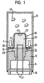
- the gas generator has a generator outer housing, consisting of a Pot-shaped part 10 made of deep-drawn sheet metal and a lid 12 with a opening having several paragraphs 14.
- the generator outer housing is gas-tight and moisture-tight, more precisely even helium-tight, made with it no moisture inside the generator outer casing during more than ten years.
- part 10 is, for example, via a Weld 16 attached to the lid 12, in addition also between separate seals can be provided in the two parts.
- the detonator has a self-contained detonator housing, which is also helium-tight and moisture-tight. Inside the The igniter housing is pyrotechnic material 20 and an early ignition charge 42 accommodated.
- the fuse housing consists of a hat-shaped, the pyrotechnic material 20 receiving receiving part 22 made of thin sheet metal, for example stainless steel, and a base part 24, through which electrical Connections 27 are led to activate the igniter.
- the receiving part 22 has a radially outward toward the base part 24 projecting, circumferential flange 26.
- the base part 24 has in the area of Flange 26 also a radially protruding, circumferential counter flange 28.
- the counter flange 28 has a smaller diameter, so that the Flange 26 has an outer edge 30 which is the area of the flange should, which protrudes radially with respect to the counter flange 28.
- flange 26 and mating flange 28 lie against one another over the full area Receiving part 22 and base part 24 by capacitor discharge welding connected gas-tight and protected against moisture ingress.
- the corresponding circumferential weld seam is designated 32.
- a second Weld 34 connects the outer edge 30, which is directly on the cover 12 is in full contact with the lid 12.
- the weld seam 34 is also by capacitor discharge welding generated. Due to the oversized flange 26, the receiving part 22 is not used only as a section of the fuse housing, but also as a seal of the Opening 14 of the generator outer housing.
- the igniter as a separate closed unit is usually made by a supplier to the generator manufacturer and can, since it is a closed housing acts, can also be temporarily stored.
- the detonator is, with reference to Figure 1, from above on the lid 12 and on this permanently fixed by capacitor discharge welding, whereby in the case of capacitor discharge welding also exerted an axial pressure on the flange 26 is symbolized by the arrows F. This pressure causes the Flange 26 pressed against the cover 12.
- a pyrotechnic is in the pot-shaped part 10
- Propellant for example a tablet-shaped propellant 40, wherein preferably the later form of the igniter 18 by a so-called Dummy is spared.
- cover 12 and cup-shaped part 10 inserted and welded together. An additional seal between the igniter 18 and the cover 12 can in the illustrated Embodiment omitted.
Landscapes
- Engineering & Computer Science (AREA)
- Physics & Mathematics (AREA)
- Fluid Mechanics (AREA)
- Mechanical Engineering (AREA)
- General Engineering & Computer Science (AREA)
- Air Bags (AREA)
Claims (7)
- Générateur de gaz pyrotechnique, comportant
un boítier extérieur de générateur dans lequel sont logés un combustible (40) pyrotechnique et un allumeur (18),
l'allumeur (18) possédant un propre boítier d'allumeur fermé sur soi-même et contenant un matériau pyrotechnique (20), qui est fixé sur le boítier extérieur de générateur, et
le boítier d'allumeur possédant une partie de socle (24) et une partie de réception (22) en forme de chapeau, fixée sur celle-ci,
la partie de réception (22) présentant une bride (26) avec un bord extérieur (30) et la bride (26) étant soudée sur la partie de socle (24),
caractérisé en ce que
la bride (26) est une bride radiale, le bord extérieur (30) faisant saillie radialement par rapport à la partie de socle (24) et étant soudé au boítier extérieur de générateur. - Générateur de gaz selon la revendication 1, caractérisé en ce que la partie de socle (24) présente une contre-bride (28) faisant saillie radialement, sur laquelle est soudée la bride (26) de la partie de réception (22).
- Générateur de gaz selon la revendication 1 ou 2, caractérisé en ce que le soudage du bord extérieur (30) et du boítier extérieur de générateur est réalisé de manière étanche aux gaz et étanche à l'humidité.
- Générateur de gaz selon l'une des revendications précédentes, caractérisé en ce que le bord extérieur (30) est fixé au boítier extérieur de générateur par soudage à décharge à condensateur.
- Générateur de gaz selon l'une des revendications précédentes, caractérisé en ce que le boítier extérieur de générateur possède une partie (10) en forme de pot et un couvercle (12) fermant celle-ci, avec une ouverture (14) pour faire passer des raccordements (27) de l'allumeur (18), la partie de réception (22) étant soudée sur le couvercle (12) et fermant l'ouverture (14).
- Générateur de gaz selon la revendication 5, caractérisé en ce que le bord extérieur (30) est en appui avec toute sa surface sur la face intérieure du couvercle (12).
- Générateur de gaz selon l'une des revendications précédentes, caractérisé en ce que l'allumeur (18) possède une composition d'allumage prématuré (42).
Applications Claiming Priority (2)
| Application Number | Priority Date | Filing Date | Title |
|---|---|---|---|
| DE20020103U | 2000-11-27 | ||
| DE20020103U DE20020103U1 (de) | 2000-11-27 | 2000-11-27 | Pyrotechnischer Gasgenerator |
Publications (2)
| Publication Number | Publication Date |
|---|---|
| EP1209045A1 EP1209045A1 (fr) | 2002-05-29 |
| EP1209045B1 true EP1209045B1 (fr) | 2004-09-22 |
Family
ID=7949344
Family Applications (1)
| Application Number | Title | Priority Date | Filing Date |
|---|---|---|---|
| EP01127429A Expired - Lifetime EP1209045B1 (fr) | 2000-11-27 | 2001-11-26 | Générateur de gaz pyrotechnique |
Country Status (3)
| Country | Link |
|---|---|
| US (1) | US6435550B1 (fr) |
| EP (1) | EP1209045B1 (fr) |
| DE (2) | DE20020103U1 (fr) |
Families Citing this family (11)
| Publication number | Priority date | Publication date | Assignee | Title |
|---|---|---|---|---|
| US6644206B2 (en) * | 2001-12-21 | 2003-11-11 | Trw Inc. | Electrically actuatable initiator with output charge |
| DE102004004748A1 (de) * | 2003-03-08 | 2004-09-23 | Dynamit Nobel Ais Gmbh Automotive Ignition Systems | Glasdurchführung für einen pyroelektrischen Anzünder |
| US7407184B2 (en) * | 2003-06-16 | 2008-08-05 | Automotive Systems Laboratory, Inc. | Micro gas generator including an initiator blast shield |
| DE102005062329A1 (de) * | 2005-06-15 | 2006-12-28 | Hirschmann Automotive Gmbh | Direktintegration der steckerseitigen Schnittstelle in die Gasgeneratorgeometrie |
| DE102007057551B4 (de) * | 2007-11-29 | 2011-11-24 | Diehl Bgt Defence Gmbh & Co. Kg | Miniaturisiertes Kraftelement |
| HUE044117T2 (hu) | 2010-09-17 | 2019-10-28 | Schott Ag | Fém-rögzítõanyag átvezetés és eljárás annak az elõállítására |
| DE102011102064A1 (de) * | 2011-05-19 | 2012-11-22 | Trw Airbag Systems Gmbh | Verfahren zur Herstellung eines Gasgenerators |
| DE102017128886A1 (de) * | 2017-12-05 | 2019-06-06 | Trw Airbag Systems Gmbh | Pyrotechnischer Gasgenerator |
| JP6954520B2 (ja) | 2017-12-05 | 2021-10-27 | 株式会社ダイセル | 点火器組立体、及びガス発生器 |
| CN117412886A (zh) | 2021-05-11 | 2024-01-16 | 株式会社大赛璐 | 点火器组装体和气体发生装置 |
| DE102022131843A1 (de) | 2022-12-01 | 2024-06-06 | Zf Airbag Germany Gmbh | Anzündeinheit eines gasgenerators und verfahren zur herstellung einer anzündeinheit |
Family Cites Families (12)
| Publication number | Priority date | Publication date | Assignee | Title |
|---|---|---|---|---|
| US3858392A (en) * | 1973-10-25 | 1975-01-07 | Ici America Inc | Controlled burning squib arrangement |
| US3990367A (en) | 1975-06-16 | 1976-11-09 | The United States Of America As Represented By The Secretary Of The Navy | Injection-molding apparatus for attaching end fittings to detonating cords |
| DE3738436C1 (de) | 1987-11-12 | 1988-11-24 | Bayern Chemie Gmbh Flugchemie | Elektrische Anzuendeinrichtung |
| DE4002088C1 (fr) | 1990-01-25 | 1990-08-23 | Bayern-Chemie Gesellschaft Fuer Flugchemische Antriebe Mbh, 8261 Aschau, De | |
| US5487559A (en) | 1994-09-13 | 1996-01-30 | Trw Inc. | Air bag inflator with pressure sensor |
| DE19601448A1 (de) | 1996-01-17 | 1997-07-24 | Temic Bayern Chem Airbag Gmbh | Verschluß für einen Gasgenerator |
| US5879025A (en) * | 1996-08-08 | 1999-03-09 | Trw Vehicle Safety Systems Inc. | Inflator for an inflatable vehicle occupant protection device |
| DE19723259A1 (de) | 1997-06-03 | 1998-12-10 | Temic Bayern Chem Airbag Gmbh | Gasgenerator sowie Verfahren zum Betreiben eines Gasgenerators |
| DE19723256A1 (de) | 1997-06-03 | 1998-12-10 | Temic Bayern Chem Airbag Gmbh | Gasgenerator |
| US6012737A (en) | 1997-11-06 | 2000-01-11 | Trw Inc. | Vehicle occupant protection apparatus |
| GB2347485A (en) * | 1999-03-05 | 2000-09-06 | Breed Automotive Tech | Pretensioner |
| DE19914241A1 (de) | 1999-03-29 | 2000-10-05 | Nico Pyrotechnik | Zündeinrichtung für eine Insassenschutzvorrichtung eines Kraftfahrzeuges |
-
2000
- 2000-11-27 DE DE20020103U patent/DE20020103U1/de not_active Expired - Lifetime
-
2001
- 2001-11-26 EP EP01127429A patent/EP1209045B1/fr not_active Expired - Lifetime
- 2001-11-26 DE DE50103735T patent/DE50103735D1/de not_active Expired - Fee Related
- 2001-11-26 US US09/994,214 patent/US6435550B1/en not_active Expired - Fee Related
Also Published As
| Publication number | Publication date |
|---|---|
| US6435550B1 (en) | 2002-08-20 |
| DE20020103U1 (de) | 2001-04-05 |
| US20020063421A1 (en) | 2002-05-30 |
| DE50103735D1 (de) | 2004-10-28 |
| EP1209045A1 (fr) | 2002-05-29 |
Similar Documents
| Publication | Publication Date | Title |
|---|---|---|
| EP1209045B1 (fr) | Générateur de gaz pyrotechnique | |
| EP3104114B1 (fr) | Réalisation de matériau de fixation en métal et procédé de fabrication d'un corps de base d'une réalisation de matériau de fixation en metal | |
| DE10324956B4 (de) | Messfühler | |
| DE102005009644B4 (de) | Zündvorrichtung für eine pyrotechnische Schutzvorrichtung, Verfahren zur Herstellung einer solchen Zündvorrichtung sowie Gasgenerator mit einer solchen Zündvorrichtung | |
| EP0704348A1 (fr) | Détonateur pour un générateur de gaz d'un dispositif, de sécurité passive | |
| EP0168588A1 (fr) | Générateur de gaz | |
| DE4138918A1 (de) | Gasgenerator, insbesondere rohrgasgenerator fuer airbag | |
| EP2195205A1 (fr) | Generateur de gaz pour un module d'airbag | |
| DE112016003039T5 (de) | Zündvorrichtung und gas-generator, welche dieselbe verwendet | |
| DE69009119T2 (de) | Sauerstoffgasdruckpatrone. | |
| DE29502825U1 (de) | Piezoresistiver Drucksensor oder Druckaufnehmer | |
| EP1335179B1 (fr) | Chaine d'amorçage électrique avec un porteur du detonateur en plastique muni d'un couche metallique insertée | |
| EP1209046A1 (fr) | Générateur de gaz | |
| DE102008049652B4 (de) | Gasgenerator mit bewegbarer Überströmöffnung | |
| DE29720819U1 (de) | Pyrotechnische Einrichtung für Fahrzeuginsassen-Schutzsysteme | |
| DE102006002435A1 (de) | Verfahren zur Herstellung eines Gasgenerators und mittels des Verfahrens hergestellter Gasgenerator | |
| DE3416735A1 (de) | Elektrisches zuendelement | |
| DE69503679T2 (de) | Endplattenanordnung für ein Fahrzeugluftsackmodul | |
| US9016203B2 (en) | Propellant charge igniter | |
| WO2010108200A1 (fr) | Unité d'agent de fonctionnement contenant un agent de fonctionnement sensible à la température pour véhicule | |
| DE19501837C2 (de) | Gasgeneratoren | |
| EP0882629A1 (fr) | Générateur de gaz | |
| DE19725475A1 (de) | Gasgenerator | |
| WO2022248382A1 (fr) | Micro-générateur de gaz et procédé de fabrication d'un micro-générateur de gaz | |
| DE102007057551B4 (de) | Miniaturisiertes Kraftelement |
Legal Events
| Date | Code | Title | Description |
|---|---|---|---|
| PUAI | Public reference made under article 153(3) epc to a published international application that has entered the european phase |
Free format text: ORIGINAL CODE: 0009012 |
|
| AK | Designated contracting states |
Kind code of ref document: A1 Designated state(s): AT BE CH CY DE DK ES FI FR GB GR IE IT LI LU MC NL PT SE TR |
|
| AX | Request for extension of the european patent |
Free format text: AL;LT;LV;MK;RO;SI |
|
| 17P | Request for examination filed |
Effective date: 20020718 |
|
| AKX | Designation fees paid |
Designated state(s): DE FR GB SE |
|
| 17Q | First examination report despatched |
Effective date: 20030515 |
|
| RBV | Designated contracting states (corrected) |
Designated state(s): DE FR GB |
|
| GRAP | Despatch of communication of intention to grant a patent |
Free format text: ORIGINAL CODE: EPIDOSNIGR1 |
|
| RBV | Designated contracting states (corrected) |
Designated state(s): DE FR GB SE |
|
| RAP1 | Party data changed (applicant data changed or rights of an application transferred) |
Owner name: TRW AIRBAG SYSTEMS GMBH |
|
| GRAS | Grant fee paid |
Free format text: ORIGINAL CODE: EPIDOSNIGR3 |
|
| GRAA | (expected) grant |
Free format text: ORIGINAL CODE: 0009210 |
|
| AK | Designated contracting states |
Kind code of ref document: B1 Designated state(s): DE FR GB SE |
|
| REG | Reference to a national code |
Ref country code: GB Ref legal event code: FG4D Free format text: NOT ENGLISH |
|
| REG | Reference to a national code |
Ref country code: IE Ref legal event code: FG4D Free format text: GERMAN |
|
| REF | Corresponds to: |
Ref document number: 50103735 Country of ref document: DE Date of ref document: 20041028 Kind code of ref document: P |
|
| GBT | Gb: translation of ep patent filed (gb section 77(6)(a)/1977) |
Effective date: 20041125 |
|
| PGFP | Annual fee paid to national office [announced via postgrant information from national office to epo] |
Ref country code: SE Payment date: 20041222 Year of fee payment: 4 |
|
| REG | Reference to a national code |
Ref country code: SE Ref legal event code: TRGR |
|
| REG | Reference to a national code |
Ref country code: IE Ref legal event code: FD4D |
|
| PLBE | No opposition filed within time limit |
Free format text: ORIGINAL CODE: 0009261 |
|
| STAA | Information on the status of an ep patent application or granted ep patent |
Free format text: STATUS: NO OPPOSITION FILED WITHIN TIME LIMIT |
|
| ET | Fr: translation filed | ||
| 26N | No opposition filed |
Effective date: 20050623 |
|
| PG25 | Lapsed in a contracting state [announced via postgrant information from national office to epo] |
Ref country code: GB Free format text: LAPSE BECAUSE OF NON-PAYMENT OF DUE FEES Effective date: 20051126 |
|
| PG25 | Lapsed in a contracting state [announced via postgrant information from national office to epo] |
Ref country code: SE Free format text: LAPSE BECAUSE OF NON-PAYMENT OF DUE FEES Effective date: 20051127 |
|
| EUG | Se: european patent has lapsed | ||
| GBPC | Gb: european patent ceased through non-payment of renewal fee |
Effective date: 20051126 |
|
| PGFP | Annual fee paid to national office [announced via postgrant information from national office to epo] |
Ref country code: FR Payment date: 20061103 Year of fee payment: 6 |
|
| PGFP | Annual fee paid to national office [announced via postgrant information from national office to epo] |
Ref country code: DE Payment date: 20061130 Year of fee payment: 6 |
|
| PG25 | Lapsed in a contracting state [announced via postgrant information from national office to epo] |
Ref country code: DE Free format text: LAPSE BECAUSE OF NON-PAYMENT OF DUE FEES Effective date: 20080603 |
|
| REG | Reference to a national code |
Ref country code: FR Ref legal event code: ST Effective date: 20080930 |
|
| PG25 | Lapsed in a contracting state [announced via postgrant information from national office to epo] |
Ref country code: FR Free format text: LAPSE BECAUSE OF NON-PAYMENT OF DUE FEES Effective date: 20071130 |