EP1209046A1 - Générateur de gaz - Google Patents
Générateur de gaz Download PDFInfo
- Publication number
- EP1209046A1 EP1209046A1 EP01127431A EP01127431A EP1209046A1 EP 1209046 A1 EP1209046 A1 EP 1209046A1 EP 01127431 A EP01127431 A EP 01127431A EP 01127431 A EP01127431 A EP 01127431A EP 1209046 A1 EP1209046 A1 EP 1209046A1
- Authority
- EP
- European Patent Office
- Prior art keywords
- gas generator
- generator according
- igniter
- cover
- housing
- Prior art date
- Legal status (The legal status is an assumption and is not a legal conclusion. Google has not performed a legal analysis and makes no representation as to the accuracy of the status listed.)
- Withdrawn
Links
- 238000003466 welding Methods 0.000 claims abstract description 8
- 239000003380 propellant Substances 0.000 claims description 9
- 238000004519 manufacturing process Methods 0.000 claims description 6
- 238000007789 sealing Methods 0.000 claims description 4
- 238000004382 potting Methods 0.000 claims description 3
- 238000001746 injection moulding Methods 0.000 claims 1
- 239000002360 explosive Substances 0.000 abstract 1
- 238000002604 ultrasonography Methods 0.000 abstract 1
- 239000002184 metal Substances 0.000 description 2
- 229910001369 Brass Inorganic materials 0.000 description 1
- 230000003213 activating effect Effects 0.000 description 1
- 230000004888 barrier function Effects 0.000 description 1
- 239000010951 brass Substances 0.000 description 1
- 238000009434 installation Methods 0.000 description 1
- 238000012423 maintenance Methods 0.000 description 1
- 238000000034 method Methods 0.000 description 1
- 238000004023 plastic welding Methods 0.000 description 1
Images

Classifications
-
- B—PERFORMING OPERATIONS; TRANSPORTING
- B60—VEHICLES IN GENERAL
- B60R—VEHICLES, VEHICLE FITTINGS, OR VEHICLE PARTS, NOT OTHERWISE PROVIDED FOR
- B60R21/00—Arrangements or fittings on vehicles for protecting or preventing injuries to occupants or pedestrians in case of accidents or other traffic risks
- B60R21/02—Occupant safety arrangements or fittings, e.g. crash pads
- B60R21/16—Inflatable occupant restraints or confinements designed to inflate upon impact or impending impact, e.g. air bags
- B60R21/26—Inflatable occupant restraints or confinements designed to inflate upon impact or impending impact, e.g. air bags characterised by the inflation fluid source or means to control inflation fluid flow
- B60R21/264—Inflatable occupant restraints or confinements designed to inflate upon impact or impending impact, e.g. air bags characterised by the inflation fluid source or means to control inflation fluid flow using instantaneous generation of gas, e.g. pyrotechnic
- B60R21/2644—Inflatable occupant restraints or confinements designed to inflate upon impact or impending impact, e.g. air bags characterised by the inflation fluid source or means to control inflation fluid flow using instantaneous generation of gas, e.g. pyrotechnic using only solid reacting substances, e.g. pellets, powder
-
- F—MECHANICAL ENGINEERING; LIGHTING; HEATING; WEAPONS; BLASTING
- F42—AMMUNITION; BLASTING
- F42B—EXPLOSIVE CHARGES, e.g. FOR BLASTING, FIREWORKS, AMMUNITION
- F42B3/00—Blasting cartridges, i.e. case and explosive
- F42B3/26—Arrangements for mounting initiators; Accessories therefor, e.g. tools
-
- B—PERFORMING OPERATIONS; TRANSPORTING
- B60—VEHICLES IN GENERAL
- B60R—VEHICLES, VEHICLE FITTINGS, OR VEHICLE PARTS, NOT OTHERWISE PROVIDED FOR
- B60R21/00—Arrangements or fittings on vehicles for protecting or preventing injuries to occupants or pedestrians in case of accidents or other traffic risks
- B60R21/02—Occupant safety arrangements or fittings, e.g. crash pads
- B60R21/16—Inflatable occupant restraints or confinements designed to inflate upon impact or impending impact, e.g. air bags
- B60R21/26—Inflatable occupant restraints or confinements designed to inflate upon impact or impending impact, e.g. air bags characterised by the inflation fluid source or means to control inflation fluid flow
- B60R2021/26029—Ignitors
Definitions
- the invention relates to a gas generator with an outer housing Plastic containing a pyrotechnic propellant and a detonator with one own detonator housing are housed.
- the aim of the invention is a gas generator to create the seal of the igniter in the plastic housing can be carried out in a simple manner and protected against moisture ingress
- the weld is an ultrasonic weld, a very inexpensive process.
- the detonator also preferably has electrical connection lines, through at least one opening in the gas generator outer housing extend.
- the fuse housing seals the opening after welding, so that no moisture can get inside the gas generator and no gas can emerge through the opening when activating the gas generator.
- the detonator more specifically, the section of the detonator that is made of plastic and on Outer housing is welded on, therefore has a double function, because it also serves as a closure for the opening for the passage of the connecting lines. Potting the openings, as has been the case in the prior art has always been proposed, can be omitted.
- the outer housing preferably has a cup-shaped receiving part for the propellant charge and a cover to which the igniter is welded.
- the Receiving part and the lid are also welded together, so that the same connection type is selected.
- a radial gap between the receiving part and the cover can be provided in which a protrusion of the igniter protrudes, whereby this is additionally secured. If necessary, this position securing absorb additional forces so that the weld seam between the igniter and Outer housing does not have to absorb the entire mechanical load.
- a particularly simple embodiment is characterized by that contact sleeves are embedded in the cover, in the contact pins on the igniter are introduced inside.
- the contact sleeves are on their outer ends further preferably connected with connection cables.
- simple electrical contacting can be achieved by using Overmoulding or potting including contact sleeves embedded in the cover Connection lines form a pre-assembled unit together with the cover, then only the igniter has to be inserted from the inside.
- Figure 1 shows a longitudinal section through an embodiment of the invention Gas generator
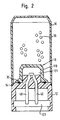
- Figure 2 shows a longitudinal section through a second embodiment of the gas generator according to the invention.
- a gas generator is shown, the outer housing of two Share consists of a pot-shaped receiving part 10 and a Receiving part 10 closing cover 12.
- Receiving part 10 and cover 12 are made of the same plastic and form a gas-tight, against moisture protected housing.
- a pyrotechnic propellant charge 16 is accommodated in the receiving part 10 and an electrical igniter 18.
- the igniter 18 has a multi-part an upper part 19 and a base 20 existing outer housing, which is preferably is completely closed to the outside, making the igniter a pre-assembled Forms a unit in which another pyrotechnic propellant charge (not shown) is included.
- the base 20 is made of plastic, the plastic is the same plastic as that for the receiving part 10 and the lid 12.
- the base 20 has a radial circumferential projection 22, which in a radial gap 24 between a radially inward projection 26 of the Receiving part 10 and a paragraph 28 in the cover 12.
- Paragraph 28 is one of the surfaces that defines an opening in the lid 12 that faces outwards passes into two small openings 30, in the contact sleeves 32 made of brass are used.
- the projection 22 of the base 20 is axially in the radial gap 24 as far as possible clamped between the receiving part 10 and the cover 12.
- the igniter 18 is attached to the cover 12 by welding between the base 20 and the cover 12, which are surrounded by a circumferential, closed weld 36 is symbolized.
- contact pins 40 emerge from the base, which are inserted into the contact sleeves 32.
- the outer ends of the contact sleeves 32 take connecting lines in the form of connecting cables 42, the outer ends of the contact sleeves 32 are pressed together, thereby the Fix cable 42.
- the manufacture of the gas generator which is preferably an extremely small one Gas generator for driving a belt tensioner is done as follows: First, the contact sleeves are connected to the connecting cables at their outer ends 42 assembled and pressed together. Then they are in a Form in which the lid 12 is injected or poured so that the Contact sleeves 32 are embedded in the cover 12. The openings 30 are thus gas-tight and sealed against the ingress of moisture without additional Sealing elements are necessary.
- the propellant charge 16 is filled into the receiving part 10, the space for the igniter 18 later projecting into the propellant charge 16 is spared.
- the electrical igniter 18 can be a housing made entirely of plastic have or only a section of plastic, such as the Base or if the housing is largely made of interconnected Sheet metal sections consists of a plastic ring, which sheet metal parts connects and seals with each other.
- the gas generator shown is characterized by small dimensions as well a simple manufacture from that in just a few manufacturing steps Maintenance of a manufacturing process (ultrasonic welding) carried out can be.
- the propellant does not have a filter chamber to provide additional installation space save up.
- This first embodiment differs from that in FIG. 2 shown embodiment in that the detonator before attachment to Outer housing has no self-contained detonator housing and thus also does not form a separately prefabricated unit. Rather, it exists Detonator housing from a cap 119, i.e. a hollow body, made of plastic, the is welded onto the cover 12.
- the reference numeral 36 denotes again the circumferential weld seam. In the cap 119 is placed on the Cover 12 filled with a primer charge.
- Potted contact pins in the cover 12 40 protrude into the space 121 delimited by the cap 119 Contact pins 40 in an opening 123 in the cover 12, in which a retaining ring including the short-circuit spring (not shown) and then a plug is introduced for connection to a trigger control.
Landscapes
- Engineering & Computer Science (AREA)
- Physics & Mathematics (AREA)
- Fluid Mechanics (AREA)
- Mechanical Engineering (AREA)
- General Engineering & Computer Science (AREA)
- Air Bags (AREA)
Applications Claiming Priority (2)
| Application Number | Priority Date | Filing Date | Title |
|---|---|---|---|
| DE20020099U | 2000-11-27 | ||
| DE20020099U DE20020099U1 (de) | 2000-11-27 | 2000-11-27 | Gasgenerator |
Publications (1)
| Publication Number | Publication Date |
|---|---|
| EP1209046A1 true EP1209046A1 (fr) | 2002-05-29 |
Family
ID=7949341
Family Applications (1)
| Application Number | Title | Priority Date | Filing Date |
|---|---|---|---|
| EP01127431A Withdrawn EP1209046A1 (fr) | 2000-11-27 | 2001-11-26 | Générateur de gaz |
Country Status (3)
| Country | Link |
|---|---|
| US (1) | US6634299B2 (fr) |
| EP (1) | EP1209046A1 (fr) |
| DE (1) | DE20020099U1 (fr) |
Families Citing this family (15)
| Publication number | Priority date | Publication date | Assignee | Title |
|---|---|---|---|---|
| US7475053B2 (en) * | 2000-07-27 | 2009-01-06 | The Johns Hopkins University | Method and system for the autonomous design of cybernetic systems |
| JP4139327B2 (ja) * | 2001-08-09 | 2008-08-27 | 日本化薬株式会社 | ガス発生器 |
| US7401810B2 (en) * | 2003-07-07 | 2008-07-22 | Autoliv Asp, Inc. | Ultrasonic welded initiator and connector socket |
| US7690303B2 (en) * | 2004-04-22 | 2010-04-06 | Reynolds Systems, Inc. | Plastic encapsulated energetic material initiation device |
| JP2006035970A (ja) * | 2004-07-26 | 2006-02-09 | Daicel Chem Ind Ltd | 点火器組立体 |
| DE202005007611U1 (de) * | 2005-05-13 | 2005-09-22 | Trw Airbag Systems Gmbh | Gasgenerator |
| DE202005016885U1 (de) * | 2005-10-27 | 2006-02-02 | Trw Airbag Systems Gmbh | Gasgenerator |
| KR101782076B1 (ko) * | 2008-09-30 | 2017-09-26 | 티알더블유 에어백 시스템즈 게엠베하 | 가스 발생기, 가스 발생기 제조 방법 및 가스 발생기를 구비하는 모듈 |
| DE102013017383A1 (de) * | 2013-10-21 | 2015-04-23 | Trw Airbag Systems Gmbh | Anzündeinheit, insbesondere für einen Gasgenerator, Gasgenerator, Gassackmodul, Fahrzeugsicherheitssystem und Verfahren zur Herstellung einer Anzündeinheit |
| US9440615B2 (en) * | 2014-12-10 | 2016-09-13 | Autoliv Asp, Inc. | Initiator assemblies |
| DE102017128886A1 (de) * | 2017-12-05 | 2019-06-06 | Trw Airbag Systems Gmbh | Pyrotechnischer Gasgenerator |
| GB2582307A (en) * | 2019-03-18 | 2020-09-23 | Eaton Intelligent Power Ltd | Switching device for fast disconnection of short-circuit currents |
| JP7730735B2 (ja) | 2021-11-30 | 2025-08-28 | 株式会社ダイセル | ガス発生器 |
| JP7756548B2 (ja) | 2021-11-30 | 2025-10-20 | 株式会社ダイセル | ガス発生器 |
| EP4442518A4 (fr) | 2021-11-30 | 2025-11-19 | Daicel Corp | Générateur de gaz |
Citations (5)
| Publication number | Priority date | Publication date | Assignee | Title |
|---|---|---|---|---|
| US3672301A (en) * | 1969-12-31 | 1972-06-27 | Aai Corp | Cartridge |
| US3990367A (en) * | 1975-06-16 | 1976-11-09 | The United States Of America As Represented By The Secretary Of The Navy | Injection-molding apparatus for attaching end fittings to detonating cords |
| US4621578A (en) * | 1983-12-28 | 1986-11-11 | Societe Nationale Des Poudres Et Explosifs | Pyrotechnic initiator using a coaxial connector |
| US5131679A (en) * | 1990-12-18 | 1992-07-21 | Trw Inc. | Initiator assembly for air bag inflator |
| US5634660A (en) * | 1994-10-01 | 1997-06-03 | Temic Bayern-Chemie Airbag Gmbh | Gas generator ignition unit for a passive restraint system |
Family Cites Families (54)
| Publication number | Priority date | Publication date | Assignee | Title |
|---|---|---|---|---|
| US2448343A (en) | 1942-12-14 | 1948-08-31 | Zandmer Solis Myron | Projectile |
| US2381130A (en) | 1943-01-25 | 1945-08-07 | Eurcka Vacuum Cleaner Company | Aircraft pyrotechnic |
| US2551596A (en) | 1946-05-21 | 1951-05-08 | Gerhard O Haglund | Aerodynamic body for carrying detection apparatus |
| US2907536A (en) | 1950-10-04 | 1959-10-06 | Helmut Ph G A R Von Zborowski | Annular wing flying machine and method of flying same |
| US2813719A (en) | 1955-07-11 | 1957-11-19 | Del Mar Engineering Lab Inc | Aircraft tow target installation |
| US2923549A (en) | 1955-10-31 | 1960-02-02 | Del Mar Engineering Lab Inc | Tow target launcher for use on airborne vehicles |
| US2953377A (en) | 1956-06-08 | 1960-09-20 | Del Mar Eng Lab | High speed externally carried tow target |
| US2998754A (en) | 1959-05-29 | 1961-09-05 | Karol J Bialy | Missile launcher |
| US3002708A (en) | 1959-09-28 | 1961-10-03 | James E Wetzel | Aircraft tow reel system |
| DE1229397B (de) | 1960-09-19 | 1966-11-24 | Del Mar Eng Lab | Vorrichtung an Schleppflugzeugen zur Aufnahme und Halterung von Schleppzielen |
| US3135511A (en) | 1961-02-27 | 1964-06-02 | Hayes Corp | Towed target |
| FR1336769A (fr) | 1962-07-23 | 1963-09-06 | Tech Et Ind | Dispositif mécanique de transmission d'un ordre à un aéronef remorqué |
| US3225655A (en) | 1964-05-25 | 1965-12-28 | Gen Dynamics Corp | Controlled tip-off launcher |
| US3410559A (en) | 1966-04-26 | 1968-11-12 | Hayes Internat Corp | Airborne target with infrared source |
| US3505926A (en) | 1968-07-09 | 1970-04-14 | Scient Prod Corp | Line throwing device |
| US3610096A (en) | 1969-01-22 | 1971-10-05 | Emerson Electric Co | Spin and fin stabilized rocket |
| US3720167A (en) | 1970-04-16 | 1973-03-13 | R Mainhardt | Rotatable rocket having means for preventing flameout due to centrifugal force created during rotation thereof |
| US3871321A (en) | 1971-07-19 | 1975-03-18 | Mine Safety Appliances Co | Self-cocking explosively actuated cable cutter |
| US3808941A (en) | 1972-02-09 | 1974-05-07 | Dynapac Inc | Dispenser for flares and the like |
| GB1434034A (en) | 1972-07-11 | 1976-04-28 | Bender Ltd F | Method and equipment for forming a single cloud of radar reflecting chaff within the atmosphere |
| US3898661A (en) | 1973-11-29 | 1975-08-05 | Us Air Force | Mini-regenerator |
| US3932057A (en) | 1974-05-08 | 1976-01-13 | Wadensten Theodore S | Noiseless air-actuated turbine-type vibrator with blades arranged in a sidewardly extending annular pattern |
| CA1109800A (fr) | 1975-07-10 | 1981-09-29 | Oliver C. Eckel | Eolienne |
| JPS5261212A (en) | 1975-11-13 | 1977-05-20 | Toyota Motor Co Ltd | Electric detonator |
| US4062112A (en) | 1977-02-17 | 1977-12-13 | Lake Hilton J | Explosively operated wire cutter |
| DE2811016C1 (de) | 1978-03-14 | 1986-07-17 | Buck Chemisch-Technische Werke Gmbh & Co, 8230 Bad Reichenhall | Wurfkoerper |
| US4205848A (en) | 1978-04-10 | 1980-06-03 | Prototype Development Associates, Inc. | Aerial gunnery target |
| US4860657A (en) | 1978-05-05 | 1989-08-29 | Buck Chemisch-Technische Werke Gmbh & Co. | Projectile |
| US4195571A (en) | 1979-04-02 | 1980-04-01 | The United States Of America As Represented By The Secretary Of The Army | Modular wheel dispenser |
| DE3031369C2 (de) * | 1980-08-20 | 1987-01-02 | Pyrotechnische Fabrik F. Feistel GmbH + Co KG, 6719 Göllheim | Pyrotechnische Ladung aus Nebelsatz und Anzündsatz und Verfahren zur Herstellung der Nebelmischung und des Anzündsatzes |
| US4406227A (en) | 1981-04-09 | 1983-09-27 | The United States Of America As Represented By The Secretary Of The Army | System for multistage, aerial dissemination and rapid dispersion of preselected substances |
| US4446793A (en) | 1981-12-28 | 1984-05-08 | Gibbs Robert L | Disk deployment of expendables |
| US4428583B1 (en) | 1982-11-19 | 1996-03-05 | Hayes Int Corp | Airborne target for generating an exhaust plume simulating that of a jet powered aircraft |
| US4607849A (en) | 1985-03-07 | 1986-08-26 | Southwest Aerospace Corporation | Jet exhaust simulator |
| US4770368A (en) | 1985-03-12 | 1988-09-13 | Southwest Aerospace Corporation | Turbine/air vent reeling machine |
| US4718320A (en) | 1987-01-12 | 1988-01-12 | Southwest Aerospace Corporation | Towed decoy system |
| US4852455A (en) | 1987-01-12 | 1989-08-01 | Southwest Aerospace Corporation | Decoy system |
| FR2616899B1 (fr) | 1987-06-16 | 1993-04-02 | Lacroix E Tous Artifices | Conteneur-disperseur de paillettes metalliques ou metallisees formant leurres electromagnetiques |
| US4796536A (en) | 1987-06-23 | 1989-01-10 | Acurex Corporation | Chaff dispenser system |
| US5074216A (en) | 1987-09-03 | 1991-12-24 | Loral Corporation | Infrared signature enhancement decoy |
| US5445078A (en) | 1989-12-14 | 1995-08-29 | Universal Propulsion Company, Inc. | Apparatus and method for dispensing payloads |
| DE4026655A1 (de) | 1990-08-23 | 1992-02-27 | Diehl Gmbh & Co | Elektrischer detonator |
| US5249924A (en) | 1992-02-21 | 1993-10-05 | Southwest Aerospace Corporation | RAM air turbine |
| US5179778A (en) | 1992-02-25 | 1993-01-19 | Dickson Lawrence J | Method and means for producing disks of tightly packed on-end aligned fibers |
| DE4214033A1 (de) | 1992-04-29 | 1993-11-04 | Dynamit Nobel Ag | Elektrisches zuendelement mit soll-entladungsstrecke |
| JP3118974B2 (ja) | 1992-08-31 | 2000-12-18 | タカタ株式会社 | エアバッグ装置 |
| US5454320A (en) | 1992-10-23 | 1995-10-03 | Quantic Industries, Inc. | Air bag initiator |
| US5492364A (en) | 1993-04-29 | 1996-02-20 | Automotive Systems Laboratory, Inc. | Rupturable plastic housing for an air bag inflator |
| US5616883A (en) * | 1994-03-18 | 1997-04-01 | Oea, Inc. | Hybrid inflator and related propellants |
| US5763817A (en) * | 1996-08-14 | 1998-06-09 | Bendix-Atlantic Inflator Company | Center gas fill inflator |
| US5887893A (en) * | 1996-11-21 | 1999-03-30 | Autoliv Asp, Inc. | Necked airbag inflator |
| JPH1199899A (ja) * | 1997-05-28 | 1999-04-13 | Trw Occupant Restraint Syst Gmbh | 乗物乗員保護装置の火工手段 |
| US5915694A (en) | 1998-01-09 | 1999-06-29 | Brum; Roger D. | Decoy utilizing infrared special material |
| DE29805027U1 (de) | 1998-03-19 | 1998-07-23 | TRW Airbag Systems GmbH & Co. KG, 84544 Aschau | Gasgenerator mit Kunststoffgehäuse |
-
2000
- 2000-11-27 DE DE20020099U patent/DE20020099U1/de not_active Expired - Lifetime
-
2001
- 2001-11-26 US US09/994,107 patent/US6634299B2/en not_active Expired - Lifetime
- 2001-11-26 EP EP01127431A patent/EP1209046A1/fr not_active Withdrawn
Patent Citations (5)
| Publication number | Priority date | Publication date | Assignee | Title |
|---|---|---|---|---|
| US3672301A (en) * | 1969-12-31 | 1972-06-27 | Aai Corp | Cartridge |
| US3990367A (en) * | 1975-06-16 | 1976-11-09 | The United States Of America As Represented By The Secretary Of The Navy | Injection-molding apparatus for attaching end fittings to detonating cords |
| US4621578A (en) * | 1983-12-28 | 1986-11-11 | Societe Nationale Des Poudres Et Explosifs | Pyrotechnic initiator using a coaxial connector |
| US5131679A (en) * | 1990-12-18 | 1992-07-21 | Trw Inc. | Initiator assembly for air bag inflator |
| US5634660A (en) * | 1994-10-01 | 1997-06-03 | Temic Bayern-Chemie Airbag Gmbh | Gas generator ignition unit for a passive restraint system |
Also Published As
| Publication number | Publication date |
|---|---|
| US20020062757A1 (en) | 2002-05-30 |
| DE20020099U1 (de) | 2001-04-05 |
| US6634299B2 (en) | 2003-10-21 |
Similar Documents
| Publication | Publication Date | Title |
|---|---|---|
| EP1209046A1 (fr) | Générateur de gaz | |
| DE4435319A1 (de) | Anzündeinheit für einen Gasgenerator eines passiven Rückhaltesystems | |
| EP0653336B1 (fr) | Générateur de gaz | |
| EP0618424A1 (fr) | Allumeur | |
| EP1960731A1 (fr) | Unite d'actionnement pyrotechnique, son procede de production, et module de poche a gaz pourvu d'une unite d'actionnement de ce type | |
| EP1721789B1 (fr) | Générateur de gaz | |
| DE102008049652B4 (de) | Gasgenerator mit bewegbarer Überströmöffnung | |
| DE112020004400T5 (de) | Zünder-Baugruppe und Verfahren zum Zusammenbau derZünder-Baugruppe | |
| WO2020025301A1 (fr) | Générateur de gaz, module et système de sécurité de véhicule ayant un générateur de gaz | |
| EP1209045B1 (fr) | Générateur de gaz pyrotechnique | |
| EP0200856A1 (fr) | Corps de grenade, notamment pour grenade à main | |
| EP1535810A2 (fr) | Générateur de gaz | |
| EP3698098A1 (fr) | Allumeur pour un générateur de gaz et procédé servant à fabriquer un allumeur | |
| WO2018197168A1 (fr) | Support d'allumeur, module, générateur de gaz ainsi que procédé de fabrication d'un générateur de gaz | |
| DE102006002435A1 (de) | Verfahren zur Herstellung eines Gasgenerators und mittels des Verfahrens hergestellter Gasgenerator | |
| DE29720819U1 (de) | Pyrotechnische Einrichtung für Fahrzeuginsassen-Schutzsysteme | |
| EP0488935A2 (fr) | Générateur de gaz, en particulier générateur de gaz tubulaire pour un coussin gonflable | |
| DE20020102U1 (de) | Pyrotechnische, gaserzeugende Vorrichtung | |
| DE102007025368A1 (de) | Anzündereinheit für einen Gasgenerator und Gasgenerator | |
| DE20307603U1 (de) | Anzünder zur Verwendung in einer Schutzvorrichtung für Fahrzeuginsassen | |
| EP1139059B1 (fr) | Dispositif d'allumage d'un système de sécurité | |
| DE112022002503T5 (de) | Zünderanordnung und Gaserzeugungsvorrichtung | |
| DE20114665U1 (de) | Hybrid-Gasgenerator | |
| DE10311626B4 (de) | Anzünder und Verfahren zu dessen Herstellung | |
| DE102017130969A1 (de) | Anzündeinheit, Gasgenerator, Gassackmodul, Fahrzeugsicherheitssystem und Verfahren zum Herstellen einer Anzündeinheit |
Legal Events
| Date | Code | Title | Description |
|---|---|---|---|
| PUAI | Public reference made under article 153(3) epc to a published international application that has entered the european phase |
Free format text: ORIGINAL CODE: 0009012 |
|
| AK | Designated contracting states |
Kind code of ref document: A1 Designated state(s): AT BE CH CY DE DK ES FI FR GB GR IE IT LI LU MC NL PT SE TR |
|
| AX | Request for extension of the european patent |
Free format text: AL;LT;LV;MK;RO;SI |
|
| 17P | Request for examination filed |
Effective date: 20020725 |
|
| RIN1 | Information on inventor provided before grant (corrected) |
Inventor name: VETTER, JOHANN Inventor name: ENZMANN, ERNST |
|
| AKX | Designation fees paid |
Designated state(s): AT DE FR SE |
|
| 17Q | First examination report despatched |
Effective date: 20030807 |
|
| STAA | Information on the status of an ep patent application or granted ep patent |
Free format text: STATUS: THE APPLICATION IS DEEMED TO BE WITHDRAWN |
|
| 18D | Application deemed to be withdrawn |
Effective date: 20031218 |