EP1209083A2 - Procédé et dispositif pour la production des emballages enveloppes et bobine - Google Patents
Procédé et dispositif pour la production des emballages enveloppes et bobine Download PDFInfo
- Publication number
- EP1209083A2 EP1209083A2 EP01126072A EP01126072A EP1209083A2 EP 1209083 A2 EP1209083 A2 EP 1209083A2 EP 01126072 A EP01126072 A EP 01126072A EP 01126072 A EP01126072 A EP 01126072A EP 1209083 A2 EP1209083 A2 EP 1209083A2
- Authority
- EP
- European Patent Office
- Prior art keywords
- strip
- strips
- tear
- film web
- film
- Prior art date
- Legal status (The legal status is an assumption and is not a legal conclusion. Google has not performed a legal analysis and makes no representation as to the accuracy of the status listed.)
- Granted
Links
Images



Classifications
-
- B—PERFORMING OPERATIONS; TRANSPORTING
- B65—CONVEYING; PACKING; STORING; HANDLING THIN OR FILAMENTARY MATERIAL
- B65B—MACHINES, APPARATUS OR DEVICES FOR, OR METHODS OF, PACKAGING ARTICLES OR MATERIALS; UNPACKING
- B65B61/00—Auxiliary devices, not otherwise provided for, for operating on sheets, blanks, webs, binding material, containers or packages
- B65B61/18—Auxiliary devices, not otherwise provided for, for operating on sheets, blanks, webs, binding material, containers or packages for making package-opening or unpacking elements
- B65B61/182—Auxiliary devices, not otherwise provided for, for operating on sheets, blanks, webs, binding material, containers or packages for making package-opening or unpacking elements by applying tear-strips or tear-tapes
-
- B—PERFORMING OPERATIONS; TRANSPORTING
- B65—CONVEYING; PACKING; STORING; HANDLING THIN OR FILAMENTARY MATERIAL
- B65B—MACHINES, APPARATUS OR DEVICES FOR, OR METHODS OF, PACKAGING ARTICLES OR MATERIALS; UNPACKING
- B65B41/00—Supplying or feeding container-forming sheets or wrapping material
- B65B41/18—Registering sheets, blanks, or webs
-
- B—PERFORMING OPERATIONS; TRANSPORTING
- B65—CONVEYING; PACKING; STORING; HANDLING THIN OR FILAMENTARY MATERIAL
- B65H—HANDLING THIN OR FILAMENTARY MATERIAL, e.g. SHEETS, WEBS, CABLES
- B65H23/00—Registering, tensioning, smoothing or guiding webs
- B65H23/02—Registering, tensioning, smoothing or guiding webs transversely
- B65H23/022—Registering, tensioning, smoothing or guiding webs transversely by tentering devices
- B65H23/025—Registering, tensioning, smoothing or guiding webs transversely by tentering devices by rollers
-
- B—PERFORMING OPERATIONS; TRANSPORTING
- B65—CONVEYING; PACKING; STORING; HANDLING THIN OR FILAMENTARY MATERIAL
- B65H—HANDLING THIN OR FILAMENTARY MATERIAL, e.g. SHEETS, WEBS, CABLES
- B65H35/00—Delivering articles from cutting or line-perforating machines; Article or web delivery apparatus incorporating cutting or line-perforating devices, e.g. adhesive tape dispensers
- B65H35/0006—Article or web delivery apparatus incorporating cutting or line-perforating devices
- B65H35/002—Hand-held or table apparatus
-
- B—PERFORMING OPERATIONS; TRANSPORTING
- B65—CONVEYING; PACKING; STORING; HANDLING THIN OR FILAMENTARY MATERIAL
- B65H—HANDLING THIN OR FILAMENTARY MATERIAL, e.g. SHEETS, WEBS, CABLES
- B65H35/00—Delivering articles from cutting or line-perforating machines; Article or web delivery apparatus incorporating cutting or line-perforating devices, e.g. adhesive tape dispensers
- B65H35/02—Delivering articles from cutting or line-perforating machines; Article or web delivery apparatus incorporating cutting or line-perforating devices, e.g. adhesive tape dispensers from or with longitudinal slitters or perforators
-
- B—PERFORMING OPERATIONS; TRANSPORTING
- B65—CONVEYING; PACKING; STORING; HANDLING THIN OR FILAMENTARY MATERIAL
- B65H—HANDLING THIN OR FILAMENTARY MATERIAL, e.g. SHEETS, WEBS, CABLES
- B65H2301/00—Handling processes for sheets or webs
- B65H2301/50—Auxiliary process performed during handling process
- B65H2301/51—Modifying a characteristic of handled material
- B65H2301/515—Cutting handled material
- B65H2301/5152—Cutting partially, e.g. perforating
-
- B—PERFORMING OPERATIONS; TRANSPORTING
- B65—CONVEYING; PACKING; STORING; HANDLING THIN OR FILAMENTARY MATERIAL
- B65H—HANDLING THIN OR FILAMENTARY MATERIAL, e.g. SHEETS, WEBS, CABLES
- B65H2511/00—Dimensions; Position; Numbers; Identification; Occurrences
- B65H2511/50—Occurence
- B65H2511/51—Presence
- B65H2511/512—Marks, e.g. invisible to the human eye; Patterns
-
- B—PERFORMING OPERATIONS; TRANSPORTING
- B65—CONVEYING; PACKING; STORING; HANDLING THIN OR FILAMENTARY MATERIAL
- B65H—HANDLING THIN OR FILAMENTARY MATERIAL, e.g. SHEETS, WEBS, CABLES
- B65H2553/00—Sensing or detecting means
- B65H2553/40—Sensing or detecting means using optical, e.g. photographic, elements
- B65H2553/41—Photoelectric detectors
-
- B—PERFORMING OPERATIONS; TRANSPORTING
- B65—CONVEYING; PACKING; STORING; HANDLING THIN OR FILAMENTARY MATERIAL
- B65H—HANDLING THIN OR FILAMENTARY MATERIAL, e.g. SHEETS, WEBS, CABLES
- B65H2801/00—Application field
- B65H2801/54—Cigarette making
-
- B—PERFORMING OPERATIONS; TRANSPORTING
- B65—CONVEYING; PACKING; STORING; HANDLING THIN OR FILAMENTARY MATERIAL
- B65H—HANDLING THIN OR FILAMENTARY MATERIAL, e.g. SHEETS, WEBS, CABLES
- B65H2801/00—Application field
- B65H2801/81—Packaging machines
-
- Y—GENERAL TAGGING OF NEW TECHNOLOGICAL DEVELOPMENTS; GENERAL TAGGING OF CROSS-SECTIONAL TECHNOLOGIES SPANNING OVER SEVERAL SECTIONS OF THE IPC; TECHNICAL SUBJECTS COVERED BY FORMER USPC CROSS-REFERENCE ART COLLECTIONS [XRACs] AND DIGESTS
- Y10—TECHNICAL SUBJECTS COVERED BY FORMER USPC
- Y10S—TECHNICAL SUBJECTS COVERED BY FORMER USPC CROSS-REFERENCE ART COLLECTIONS [XRACs] AND DIGESTS
- Y10S493/00—Manufacturing container or tube from paper; or other manufacturing from a sheet or web
- Y10S493/916—Pliable container
- Y10S493/93—Pliable container having tear strip
-
- Y—GENERAL TAGGING OF NEW TECHNOLOGICAL DEVELOPMENTS; GENERAL TAGGING OF CROSS-SECTIONAL TECHNOLOGIES SPANNING OVER SEVERAL SECTIONS OF THE IPC; TECHNICAL SUBJECTS COVERED BY FORMER USPC CROSS-REFERENCE ART COLLECTIONS [XRACs] AND DIGESTS
- Y10—TECHNICAL SUBJECTS COVERED BY FORMER USPC
- Y10S—TECHNICAL SUBJECTS COVERED BY FORMER USPC CROSS-REFERENCE ART COLLECTIONS [XRACs] AND DIGESTS
- Y10S493/00—Manufacturing container or tube from paper; or other manufacturing from a sheet or web
- Y10S493/963—Opener, e.g. tear strip
Definitions
- the invention relates to a method for producing packs with an outer wrapper made of (clear) film and with a tear strip attached to the outer wrapping, with blanks for the outer wrapping of a continuous film web can be separated with tear strips.
- the invention further relates to a device to carry out the method and a specially trained bobbin for a strip of material.
- Packs with contents of different types, especially cigarette packs, are many provided with an outer covering made of, in particular, transparent film, which with Can be removed with the help of a tear strip.
- the tear strip usually has a colored handle end.
- the invention is concerned with measures for attaching the tear strip to the Outer wrapping or on the film web for producing blanks for outer wrappings.
- the invention has for its object to take measures for optimal provision and exact positioning of the tear strip and / or for the exact manufacture the blanks with tear strips.
- This printing can be simple colored or high-contrast markings or trade marks. However, informational printing, advertising or manufacturer information, which is a scannable marking on the material strip form. This is recognized by optoelectronic sensors, namely print mark readers and to control the conveyor drive for the film web and / or the material strip used or for the control of separators for tearing tear strips from the material strip or from cuts from the film web. If the film web or the material strip itself is influenced, this is done accordingly controlled drive of conveyor elements, in particular conveyor rollers.
- Another special feature of the invention is measures for a two-track mode of operation.
- a double-wide film web is cut in the middle to form individual ones Film webs.
- Each of these film webs becomes a strip of material for the tear strip made available.
- the two separate tear strips or material strips can either separately from two separate bobbins or by separating one in the middle double wide strips of material are made available to the film webs.
- each strip of material is assigned a strip bobbin, from which Strips of material for each film web are pulled off in an exact, synchronously controlled movement become.
- the strips of material are in line on the strip reels Structure wound, in particular in such a way that when the strip bobbins run in sync, the material strips always in a parallel relative position from the assigned bobbin subtracted from.
- the arrangement of the two bobbins on one is particularly important common carrier, in particular on a common, appropriately dimensioned Bobbin core.
- the material web is also provided with printing or markings that are scanned by assigned print mark readers become. This increases the accuracy of the control for exact Positioning of tear strips and / or separating cuts possible.
- the exemplary embodiments in the drawings deal with the production of cuboid (Cigarette) packs 10 with a conventional outer wrapper made of thin, clear film.
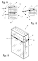
- the packs 10 can be of the hinge-lid type (Fig. 13) or soft cup. But there are also other types of packs provided with an outer covering.
- the outer wrapping surrounding the pack 10 on all sides is made by a blank 11 formed, which completely surrounds the pack.
- the upper area of the pack 10 is the outer covering or the blank 11 with a provided tear strip 12 all around.
- the tear strip 12 is on one outer end with a detectable handle end 57, which is marked by a color 58 is marked.
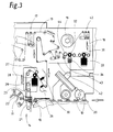
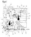
- the packaging machine for attaching the outer wrapper to the packages 10 processes a continuous film web 13 made of thin, tearable film. Of this the blanks 11 are cut off in the region of a blanking station 14 and passed to the Hand packs of 10. The film web 13 is continuously activated by one Pulled off Bobine 15. A replacement bobbin 16 is available in each case.
- the film web 13 is over a plurality of deflection rollers and a compensating pendulum 17 out. The latter enables compensation in the event of increased or reduced conveying speed of the film web 13.
- the tear strip 12 is made of a suitably designed continuous material strip 18 separated. This is also subtracted from a strip bobbin 19.
- the material strip 18 is coated on one side with an adhesive, the one Connection of the material strip 18 or the tear strip 12 separated therefrom with the film web 13 made possible by gluing.
- the packs 10 coming from a packaging machine are on a Packing web 20 fed to the cutting station 14.
- a Packing web 20 fed to the cutting station 14.
- the respective pack 10 is cut across the plane of the blank being kept ready 11 conveyed through, the blank 11 with a U-shaped envelope of Pack 10 carried by this and both inserted into a folding turret 22 become.
- the cut 11 or Packings 10 provided from the outer turret 22.
- the tear strip 12 can in various ways with the film web 13 or Blank 11 can be associated. So it is possible to use the continuous strip of material 18 lead to the film web 13 and connect to it. On Separating unit 23, each with a rotating knife and a fixed counter knife then also cuts the tear strip 12 from the material strip with the blank 11 18 from (solution according to FIG. 2 and FIG. 5).
- the material strip 18 for producing the tear strips 12 is provided with at least one imprint. This will applied in industrial production of the material strip 18 by suitable printing units. These can be markings, namely colored or black ones Brands.
- the material strip 18 is positioned precisely at intervals markings for the end of the handle.
- print with content or decorative design attached be, for example, manufacturer information etc.
- the film web 13 with prints, markings or the like provided, which are also attached precisely in the manufacture of the film web 13 become. Again, it can be informative or decorative prints, in the simple case, however, act as print marks 25.
- the existing prints, markings etc. are scanned through optoelectronic touch sensors.
- the sampled data about any relative positions the prints, markings etc. are used to adjust the film web 13, the material strip 18, the tear strip 12 or the separating cut.
- the print mark reader 26 is equipped with a known evaluation unit (not shown) connected. This in turn controls the conveying movement of the film web 13 as required any deviations found. In the exemplary embodiment, these relate to Fig. 2 (and Fig. 5) the correct positioning of the separating cut by the separating unit 23. Misalignments are caused by a change in the drive of the film web 13 balanced.
- the film web 13 is adjacent in the area conveyed to the cutting station 14 by drive rollers 27, 28, at least of which a drive roller 28 is connected to a controllable drive, namely a Servomotor 29.
- a drive roller 28 is connected to a controllable drive, namely a Servomotor 29.
- the drive roller 28 is for this purpose with a suitable outer coating made of a material with increased frictional resistance, for example rubber material, Plastic or silicone provided.
- the film web 13 provided with prints, namely, for example, with print marks 25.
- print marks 25 are recognized by an associated print mark reader 30, which here on the Print mark reader 26 is positioned opposite side.
- the print mark reader too 30 is connected to the evaluation unit.
- the material strip 18 is around a first conveyor roller 31 and then guided around a second conveyor roller 32.
- Adequate The material strip 18 is deflected in the region of the conveyor rollers 31, 32 in each case caused by two deflection rollers arranged on both sides of the conveyor rollers 31, 32.
- the conveyor roller 31 is connected to a controllable drive, namely a Servo motor 33. This can be controlled by the print mark readers 26 and / or 30.
- the Servo motor 33 and the conveyor roller 31 cooperate with the conveyor roller 32, the is driven by a motor 34, which is also a servo motor can act.
- Both conveyor rollers 31 and 32 are formed on the surface so that they can transmit a driving force on the material strip 18.
- the servo motor 33 can be used to change the relative position of the tear strip 12 or this attached printing (mark 24) can be controlled.
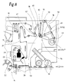
- Fig. 4 and Fig. 7 show a solution in which the tear strips 12 from the material strip 18 separated and then transferred to the film web 13 in the correct position become.
- the film web 13 is guided over a suction roller 35, which is the individual tear strips 12 also transported along the circumference and to the film web 13 creates.
- the adhesive layer of the tear strips 12 is directed outwards.
- a suction unit is arranged upstream of the suction roller 35, namely a rotating knife roller 36, the one in cooperation with the circumference of the suction roller 35 as a tear strip 12 serving section separates the material strip 18 and to the suction roller 35 passes.
- tear strips 12 or strips of material 18 and Foil web 13 provided with prints, markings or print marks, which one on top of the other are to be coordinated.
- the print mark reader 26 is assigned to the markings 24.
- Print mark reader 30 controls a drive of the material strip 18, specifically a conveyor roller 37, which is driven by a controlled servo motor 38. By steering rollers sufficient wrap around the conveyor roller 37 is ensured. This is in The conveying direction of the material strip 18 is positioned immediately adjacent to the knife roller 36.
- the conveyor roller 37 can according to recognized misalignments of the printing driven in the sense of a higher or a reduced conveying speed his.
- Gaps occur between the tear strips 12 lying against the film web 13.
- a special feature are measures for a two-lane operation with simultaneous Production of two blanks 11 (with tear strips 12).
- the cutting station 14 two foil webs 13 are spaced apart in the same plane in the transverse direction conveyed.
- the two film webs 13 are run through by a double web 39 central separation with a fixed knife 40 and spreading generated.
- the two film webs 13 are two strips of material 18 with a corresponding one Distance from each other.
- a double strip 41 is available a double-width strip of material. It is printed in full width provided, for example with markings 24, such that after division of the double strip 41, each material strip 18 has the markings 24.
- the Double strip 41 is a deflection roller 42 of a separation station over deflection rollers fed. In its area, the double strip 41 is severed in the middle a rotating circular knife 43 which works together with a support roller 44. The separating cut is carried out in the region of a circumferential groove of the support roller 44.
- Each film web 13 can have a monitoring device with print mark readers 26, 30 be assigned in the described embodiment, but it has been recognized that a sufficiently precise control of both film webs 13 with respect to the tear strips 12 is possible if only one film web 13 is checked.
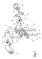
- FIG. 6 shows a perspective view of the material flow for the exemplary embodiment 3, that is, with a control of the movement of the material strip 18 or Double strip 41 through the conveyor rollers 31 and 32.
- the central severing of the Double stripe 41 takes place after the compensating pendulum 42, namely in the 5 described manner.
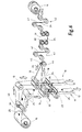
- FIG. 7 is the perspective illustration of the exemplary embodiment according to FIG. 4, however without representation of the conveyor roller 37. That of a common bobbin, namely Strip bobbin 19 double strips 41 removed before the tear strips are separated 12, that is, divided in the conveying direction in front of the knife roller 36. The strips of material formed 18 are spaced apart and separate knife rollers 36 and subsequent suction rollers 35 fed, as in the context described with Fig. 4.
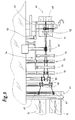
- the two closely adjacent material strips 18 initially run over a deflection roller 48, which is axially parallel to the strip bobbin 45 on a movable support, namely, a one-armed, curved or angular support lever 49 is mounted is. This is in a fixed position at one end remote from the deflection roller 48 Pivot bearing 50 mounted.
- the deflection roller is adjacent to the (variable) circumference the strip bobbin 45 is supported or lies against the circumference thereof.
- the two strips of material 18 are deflected by the deflection roller 48 guided a first spreader, namely over two arranged at a short distance from each other Spreading rollers 51, 52 on a support rod connected to the support lever 49 are stored.
- the two strips of material 18 then run - still at a short distance from one another - About a double role 53 as another management body.
- the one with two separate ones Raceways provided double roller 53 is above the strip reel 45 and the Support lever 49 and also above a compensation pendulum 54 with a plurality arranged by relatively movable pendulum rollers.
- a compensation pendulum 54 with a plurality arranged by relatively movable pendulum rollers.
- fixed guide rollers 55, 56 are mounted between the pendulum rollers of the compensating pendulum 54. These have depressions arranged along the circumference for guiding the two Material strips 18 with increasing distance from each other. Then follow in the direction of conveyance two guide members with pairs of guide rollers 59, 60.
- the guide rollers 59 are in a lower area and the guide rollers 60 stored in an upper area, so that in each case a large wrap angle the material strip 18 is given. This also applies to the positioning of the in Direction of conveyance in front of deflection and guide elements.
- the two material strips 18 are in the region of a deflecting roller of the (two) film webs 13, namely in the region of a merging roller 61 on the outside of the film webs 13 created.
- a guide for the two strips of material 18 attached which guides exactly the required distance between the two strips of material 18th from each other.
- These are two with a guide groove Guide rollers 62 on a common support rod.
- the device 8, 9 in the sense of the examples described above, in particular corresponding to FIG. 2.
- FIG. 10 A special feature is shown in FIG. 10.
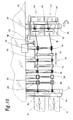
- two Material strips 18 wound on two separate bobbins, namely single bobbins 46, 47.
- the winding structure of the material strips 18 is identical, so that in synchronous controlled drive when unwinding the two strips of material 18, these are always parallel be performed at a specified distance from each other.
- a special feature according to Fig. 10 is that the two individual bobbins 46, 47 on a common support member are wound, namely on a common, sleeve-shaped bobbin core 63. Die the two individual bobbins 46, 47 are independent units with a short distance between them wound.
- a matching winding structure In the manufacture of the individual bobbins 46, 47 on a common Bobbin core 63 is expediently created a matching winding structure, so that the two strips of material 18 parallel and in a corresponding relative position can be subtracted from markings from the two individual bobbins 46, 47.
- the Bobinenkem 63 rests with a usual center opening on a trunnion 65, which is driven in rotation.
- the guide members for the two strips of material 18 are analogous to FIG. 9 formed so that the side view of FIG. 8 also on the embodiment 10 applies.
- the double roller 53 is broken down into two in a corresponding manner Distance from each other rollers 64. These bring about an alignment of the when unwinding across the width of the individual bobbins 46, 47 material strips 18 to a certain, parallel winding direction.
- the guide rollers 55 and 56 are in with provided a larger distance from each other arranged guide grooves.
- the guide rollers 62 are designed and arranged in the same way as in the embodiment 9. This also applies to the rest of the device.
- the special design of the bobbins and their handling according to FIGS. 11 and Fig. 12 can also be used with other (narrow) material webs, if two or more webs are to be processed simultaneously and synchronously.
Landscapes
- Engineering & Computer Science (AREA)
- Mechanical Engineering (AREA)
- Auxiliary Devices For And Details Of Packaging Control (AREA)
- Wrappers (AREA)
- Making Paper Articles (AREA)
Applications Claiming Priority (4)
| Application Number | Priority Date | Filing Date | Title |
|---|---|---|---|
| DE10058575 | 2000-11-24 | ||
| DE10058575 | 2000-11-24 | ||
| DE10105486A DE10105486A1 (de) | 2000-11-24 | 2001-02-07 | Verfahren und Vorrichtung zum Herstellen von Packungen mit Außenumhüllung |
| DE10105486 | 2001-02-07 |
Publications (3)
| Publication Number | Publication Date |
|---|---|
| EP1209083A2 true EP1209083A2 (fr) | 2002-05-29 |
| EP1209083A3 EP1209083A3 (fr) | 2002-10-23 |
| EP1209083B1 EP1209083B1 (fr) | 2004-08-18 |
Family
ID=26007786
Family Applications (1)
| Application Number | Title | Priority Date | Filing Date |
|---|---|---|---|
| EP01126072A Expired - Lifetime EP1209083B1 (fr) | 2000-11-24 | 2001-11-02 | Procédé et dispositif pour la production des emballages enveloppes et bobine |
Country Status (5)
| Country | Link |
|---|---|
| US (1) | US7179215B2 (fr) |
| EP (1) | EP1209083B1 (fr) |
| JP (1) | JP3970584B2 (fr) |
| CN (1) | CN1191178C (fr) |
| BR (1) | BR0105446B1 (fr) |
Cited By (6)
| Publication number | Priority date | Publication date | Assignee | Title |
|---|---|---|---|---|
| DE10246437A1 (de) * | 2002-10-04 | 2004-04-15 | Focke Gmbh & Co. Kg | Verfahren und Vorrichtung zum Erkennen eines Aufreißstreifens an einer Materialbahn |
| WO2005066038A1 (fr) * | 2003-12-31 | 2005-07-21 | Philip Morris Products S.A. | Pellicules destinees a envelopper des paquets et procedes de fabrication |
| WO2005105583A1 (fr) * | 2004-04-27 | 2005-11-10 | Focke & Co. (Gmbh & Co. Kg) | Dispositif pour produire des paquets de cigarettes |
| ITBO20090317A1 (it) * | 2009-05-15 | 2010-11-16 | Gd Spa | Macchina e metodo per l'impacchettamento di sigarette. |
| GB2499258A (en) * | 2012-02-13 | 2013-08-14 | British American Tobacco Co | Various Wrappers with Tear Strips for Multiple Containers |
| WO2023041503A1 (fr) * | 2021-09-16 | 2023-03-23 | Albert Slot | Dispositif et procédé d'application de parties d'une bande de matériau sur des flans individuels destinés à la fabrication d'un emballage |
Families Citing this family (3)
| Publication number | Priority date | Publication date | Assignee | Title |
|---|---|---|---|---|
| EP2485955B1 (fr) * | 2009-10-08 | 2018-03-28 | Illinois Tool Works Inc. | Partie de conteneur pour un carton pourvu d'une étiquette fermoir refermable en plastique |
| WO2015128794A1 (fr) | 2014-02-28 | 2015-09-03 | G.D S.P.A. | Procédé pour vérifier la position d'une étiquette adhésive sur un matériau en feuille |
| CN104309166B (zh) * | 2014-09-29 | 2017-01-11 | 任杰 | 一种塑料袋一体式生产设备 |
Family Cites Families (35)
| Publication number | Priority date | Publication date | Assignee | Title |
|---|---|---|---|---|
| US2334381A (en) * | 1940-02-20 | 1943-11-16 | Wilhelm B Bronander | Method of making tear strip wrappers |
| US2683401A (en) * | 1951-08-17 | 1954-07-13 | Battle Creek Bread Wrapping Machine Co | Method and apparatus for applying rip strips to wrapping sheets |
| US2864285A (en) * | 1954-05-24 | 1958-12-16 | S & S Corrugated Paper Mach | Taping machine |
| US3013368A (en) * | 1957-12-16 | 1961-12-19 | Cons Lithographing Corp | Wrapping and tear banding machine |
| US2983091A (en) * | 1959-04-07 | 1961-05-09 | Int Cigar Mach Co | Cigar packaging machine |
| GB1057022A (en) | 1962-08-10 | 1967-02-01 | Molins Organisation Ltd | Improvements in or relating to the wrapping of articles |
| US3272673A (en) * | 1963-05-14 | 1966-09-13 | Focke Pfuhl Verpack Automat | Method of and device for providing wrapping material with a pull strip |
| US3551245A (en) * | 1966-07-12 | 1970-12-29 | American Mach & Foundry | Method and means for forming from and securing to thin wrapper webs a reinforced tear strip |
| FR1487209A (fr) * | 1966-07-21 | 1967-06-30 | Amf Sasib | Procédé et appareil pour former et fixer une bandelette d'ouverture renforcée sur une bande mince d'enveloppement |
| US3877633A (en) * | 1973-05-23 | 1975-04-15 | Christopher Peck | Tear strip for packages |
| JPS5850385B2 (ja) | 1978-03-08 | 1983-11-10 | 富士通株式会社 | 自動印字装置 |
| DE3026856A1 (de) | 1980-07-16 | 1982-02-04 | Hoechst Ag, 6000 Frankfurt | Verfahren und vorrichtung zur herstellung von verpackungen mit deckungsgleichen markierungen, insbesondere druckmustern, auf der vorder- und rueckseite |
| DE3123544C2 (de) | 1981-06-13 | 1983-04-14 | Maschinenfabrik Alfred Schmermund Gmbh & Co, 5820 Gevelsberg | "Vorrichtung zum Zu- und Zusammenführen einer Verpackungsmaterialbahn und einer Aufreißfadenbahn" |
| JPS58201611A (ja) | 1982-05-19 | 1983-11-24 | Toyo Shokuhin Kikai Kk | 素材の貼合わせ装置 |
| JPS6045138A (ja) | 1983-08-06 | 1985-03-11 | 富士木材株式会社 | 段ボ−ル及び段ボ−ル箱 |
| JPH0330245Y2 (fr) * | 1985-03-29 | 1991-06-26 | ||
| DE3618736A1 (de) * | 1986-06-04 | 1987-12-10 | Schmermund Maschf Alfred | Verfahren und vorrichtung zum einhuellen von zigarettenpaeckchen in klarsichtfolie |
| US4836378A (en) * | 1987-11-18 | 1989-06-06 | Philip Morris, Incorporated | Package having magnetically coded tear tape or sealing strip |
| US4947994A (en) * | 1988-05-25 | 1990-08-14 | Scepter Manufacturing Company Limited | Container wrapper, and methods and apparatus for making same |
| DE3915192A1 (de) * | 1989-05-10 | 1990-11-15 | Focke & Co | Verfahren und vorrichtung zum herstellen von (folien-)verpackungen sowie (folien-)verpackung |
| US5085725A (en) | 1990-08-06 | 1992-02-04 | The United States Of America As Represented By The Secretary Of The Army | Method of chemical bonding of solid propellant grains to the internal insulation of an interceptor motor |
| US5104366A (en) * | 1991-05-15 | 1992-04-14 | B. Bunch Company, Inc. | Apparatus for folding a series of separated business forms with the top sheet of each form in a common orientation |
| US5470300A (en) * | 1992-09-09 | 1995-11-28 | Ro-An Industries Corporation | Web registration system and method |
| IT1274901B (it) * | 1994-09-12 | 1997-07-25 | Gd Spa | Metodo e dispositivo per l'alimentazione di un materiale di incarto e di un nastrino a strappo ad una macchina utlizzatrice. |
| US5483893A (en) * | 1995-03-31 | 1996-01-16 | Isaac; Ragy | Control system and method for automatically identifying webs in a printing press |
| DE19541541A1 (de) | 1995-11-08 | 1997-05-15 | Focke & Co | Verpackung für insbesondere Zigaretten sowie Verfahren und Vorrichtung zum Herstellen derselben |
| US5928749A (en) * | 1995-11-22 | 1999-07-27 | Forman; Harold M | Resealable package, and apparatus for and method of making same |
| DE19616871A1 (de) * | 1996-04-26 | 1997-10-30 | Focke & Co | Verpackung für Tabakwaren, insbesondere Zigaretten sowie Verfahren und Vorrichtung zum Herstellen derselben |
| DE19619558A1 (de) | 1996-05-14 | 1997-11-20 | Focke & Co | Vorrichtung zum Verbinden eines Aufreißstreifens mit einer Folienbahn |
| DE19733794A1 (de) * | 1997-08-05 | 1999-02-11 | Focke & Co | Packung für Zigaretten o. dgl. sowie Verfahren und Vorrichtung zum Herstellen derselben |
| DE19804735B4 (de) * | 1998-02-06 | 2006-06-29 | Windmöller & Hölscher Kg | Verfahren und Vorrichtung zum Ausrichten zweier zu einer mehrlagigen Bahn zusammengeführter Bahnen |
| IT1300042B1 (it) * | 1998-05-18 | 2000-04-04 | Azionaria Costruzioni Acma Spa | Metodo di incarto, particolarmente per prodotti alimentari quali cioccolatini e simili, e confezione ottenuta. |
| DE19824797B4 (de) | 1998-06-03 | 2004-02-12 | Indag Gesellschaft für Industriebedarf mbH & Co. Betriebs KG | Beutelherstellungsvorrichtung und Verfahren zum Herstellen von Folienbeutel |
| JP3721276B2 (ja) | 1999-02-12 | 2005-11-30 | 日本たばこ産業株式会社 | ラッピング装置 |
| DE19913855A1 (de) * | 1999-03-26 | 2000-09-28 | Focke & Co | Verfahren und Vorrichtung zum Bedrucken von Zuschnitten |
-
2001
- 2001-11-02 EP EP01126072A patent/EP1209083B1/fr not_active Expired - Lifetime
- 2001-11-14 US US09/990,796 patent/US7179215B2/en not_active Expired - Fee Related
- 2001-11-23 CN CNB011394218A patent/CN1191178C/zh not_active Expired - Fee Related
- 2001-11-23 BR BRPI0105446-5A patent/BR0105446B1/pt not_active IP Right Cessation
- 2001-11-26 JP JP2001359436A patent/JP3970584B2/ja not_active Expired - Fee Related
Cited By (10)
| Publication number | Priority date | Publication date | Assignee | Title |
|---|---|---|---|---|
| DE10246437A1 (de) * | 2002-10-04 | 2004-04-15 | Focke Gmbh & Co. Kg | Verfahren und Vorrichtung zum Erkennen eines Aufreißstreifens an einer Materialbahn |
| DE10246437A8 (de) | 2002-10-04 | 2004-09-16 | Focke & Co. (Gmbh & Co.) | Verfahren und Vorrichtung zum Erkennen eines Aufreißstreifens an einer Materialbahn |
| US7275438B2 (en) | 2002-10-04 | 2007-10-02 | Focke & Co. (Gmbh & Co. Kg) | Method and device for recognition of a tear-off strip on a material web |
| WO2005066038A1 (fr) * | 2003-12-31 | 2005-07-21 | Philip Morris Products S.A. | Pellicules destinees a envelopper des paquets et procedes de fabrication |
| WO2005105583A1 (fr) * | 2004-04-27 | 2005-11-10 | Focke & Co. (Gmbh & Co. Kg) | Dispositif pour produire des paquets de cigarettes |
| ITBO20090317A1 (it) * | 2009-05-15 | 2010-11-16 | Gd Spa | Macchina e metodo per l'impacchettamento di sigarette. |
| EP2253547A1 (fr) * | 2009-05-15 | 2010-11-24 | G.D Societa' per Azioni | Machine et procédé pour emballer des cigarettes |
| US8387345B2 (en) | 2009-05-15 | 2013-03-05 | G. D Societa' Per Azioni | Cigarette packing machine and method |
| GB2499258A (en) * | 2012-02-13 | 2013-08-14 | British American Tobacco Co | Various Wrappers with Tear Strips for Multiple Containers |
| WO2023041503A1 (fr) * | 2021-09-16 | 2023-03-23 | Albert Slot | Dispositif et procédé d'application de parties d'une bande de matériau sur des flans individuels destinés à la fabrication d'un emballage |
Also Published As
| Publication number | Publication date |
|---|---|
| BR0105446B1 (pt) | 2009-12-01 |
| CN1356238A (zh) | 2002-07-03 |
| US7179215B2 (en) | 2007-02-20 |
| JP2002211522A (ja) | 2002-07-31 |
| BR0105446A (pt) | 2002-07-09 |
| EP1209083A3 (fr) | 2002-10-23 |
| EP1209083B1 (fr) | 2004-08-18 |
| JP3970584B2 (ja) | 2007-09-05 |
| CN1191178C (zh) | 2005-03-02 |
| US20020065181A1 (en) | 2002-05-30 |
Similar Documents
| Publication | Publication Date | Title |
|---|---|---|
| DE60102898T2 (de) | Zigarettenschachtel und entsprechendes herstellungsverfahren | |
| EP1038780B1 (fr) | Procédé et dispositif pour imprimer des flans | |
| EP0176789B1 (fr) | Procédé et dispositif de changement des bobines relatif aux machines d'emballage | |
| EP0773165B1 (fr) | Dispositif pour la fabrication d'emballages, notamment de paquets de cigarettes, ayant une enveloppe exterieure transparente pourvue d'une étiquette | |
| DE2407767C3 (de) | Verfahren und Vorrichtung zum Einschlagen von Zigarettengruppen o.dgl | |
| DE102009004134A1 (de) | Verfahren und Vorrichtung zum Herstellen von Gebindepackungen sowie Gebindepackung | |
| EP2415590A2 (fr) | Dispositif de fabrication de sachets de tabac | |
| DD296641A5 (de) | On-line-praegevorrichtung fuer beschriftungsmaschinen | |
| EP3704029B1 (fr) | Procédé et dispositif pour appliquer des étiquettes sur des boites de cigarettes | |
| EP1954568B1 (fr) | Dispositif pour fabriquer des pieces decoupees pour une enveloppe interne d'un groupe de cigarettes | |
| DE2660035B1 (de) | Vorrichtung zum Abstreifen von gestanzten Abschnitten oder Ausschnitten aus Wellpappe- oder Kartonzuschnitten | |
| EP1209083B1 (fr) | Procédé et dispositif pour la production des emballages enveloppes et bobine | |
| EP1425232A1 (fr) | Emballage pourvu d'un fil de rupture, procede et dispositif de fabrication associes | |
| EP0523346B1 (fr) | Dispositif de transport d'une bande de papier dans une plieuse pour une presse d'impression | |
| EP1016593A1 (fr) | Paquet de cigarettes ainsi que procédé et dispositif pour sa fabrication | |
| EP0905027B1 (fr) | Procédé et dispositif pour la fabrication de paquets de cigarettes | |
| EP4622878A1 (fr) | Procédé et dispositif de manipulation de matériau d'emballage et emballage pour produits de l'industrie des cigarettes | |
| EP1726535A1 (fr) | Emballage avec ligne d'affaiblissement et méthode et appareil pour sa production | |
| DE10105486A1 (de) | Verfahren und Vorrichtung zum Herstellen von Packungen mit Außenumhüllung | |
| EP0917947B1 (fr) | Procédé et dispositif pour la fabrication de boítes à couvercle rabattant pour des cigarettes | |
| DE102007010994A1 (de) | Verfahren und Vorrichtung zum Auftragen von Abschnitten eines Bandmaterials auf bewegte Zuschnitte | |
| EP1742844B1 (fr) | Dispositif pour produire des paquets de cigarettes | |
| DE10352621B4 (de) | Verfahren zur seitlichen Ausrichtung einer Bahn | |
| DE102013113289A1 (de) | Vorrichtung sowie Verfahren zum Schneiden eines Bahnmaterials in Teilbahnen und Spreizen der Teilbahnen | |
| DE2949882C2 (de) | Verfahren zum Etikettieren und Foliieren von Flaschen |
Legal Events
| Date | Code | Title | Description |
|---|---|---|---|
| PUAI | Public reference made under article 153(3) epc to a published international application that has entered the european phase |
Free format text: ORIGINAL CODE: 0009012 |
|
| AK | Designated contracting states |
Kind code of ref document: A2 Designated state(s): AT BE CH CY DE DK ES FI FR GB GR IE IT LI LU MC NL PT SE TR |
|
| AX | Request for extension of the european patent |
Free format text: AL;LT;LV;MK;RO;SI |
|
| PUAL | Search report despatched |
Free format text: ORIGINAL CODE: 0009013 |
|
| RIC1 | Information provided on ipc code assigned before grant |
Free format text: 7B 65B 41/18 A, 7B 31B 19/90 B, 7B 65B 61/18 B |
|
| AK | Designated contracting states |
Kind code of ref document: A3 Designated state(s): AT BE CH CY DE DK ES FI FR GB GR IE IT LI LU MC NL PT SE TR |
|
| AX | Request for extension of the european patent |
Free format text: AL;LT;LV;MK;RO;SI |
|
| 17P | Request for examination filed |
Effective date: 20021018 |
|
| 17Q | First examination report despatched |
Effective date: 20030214 |
|
| AKX | Designation fees paid |
Designated state(s): CH DE FR GB IT LI NL |
|
| GRAP | Despatch of communication of intention to grant a patent |
Free format text: ORIGINAL CODE: EPIDOSNIGR1 |
|
| GRAS | Grant fee paid |
Free format text: ORIGINAL CODE: EPIDOSNIGR3 |
|
| GRAA | (expected) grant |
Free format text: ORIGINAL CODE: 0009210 |
|
| AK | Designated contracting states |
Kind code of ref document: B1 Designated state(s): CH DE FR GB IT LI NL |
|
| REG | Reference to a national code |
Ref country code: GB Ref legal event code: FG4D Free format text: NOT ENGLISH |
|
| REG | Reference to a national code |
Ref country code: CH Ref legal event code: EP |
|
| REG | Reference to a national code |
Ref country code: IE Ref legal event code: FG4D Free format text: GERMAN |
|
| REF | Corresponds to: |
Ref document number: 50103302 Country of ref document: DE Date of ref document: 20040923 Kind code of ref document: P |
|
| GBT | Gb: translation of ep patent filed (gb section 77(6)(a)/1977) |
Effective date: 20040917 |
|
| REG | Reference to a national code |
Ref country code: CH Ref legal event code: NV Representative=s name: R. A. EGLI & CO. PATENTANWAELTE |
|
| RAP2 | Party data changed (patent owner data changed or rights of a patent transferred) |
Owner name: FOCKE & CO. (GMBH & CO. KG) |
|
| NLT2 | Nl: modifications (of names), taken from the european patent patent bulletin |
Owner name: FOCKE & CO. (GMBH & CO. KG) |
|
| REG | Reference to a national code |
Ref country code: IE Ref legal event code: FD4D |
|
| PLBE | No opposition filed within time limit |
Free format text: ORIGINAL CODE: 0009261 |
|
| STAA | Information on the status of an ep patent application or granted ep patent |
Free format text: STATUS: NO OPPOSITION FILED WITHIN TIME LIMIT |
|
| ET | Fr: translation filed | ||
| 26N | No opposition filed |
Effective date: 20050519 |
|
| PGFP | Annual fee paid to national office [announced via postgrant information from national office to epo] |
Ref country code: FR Payment date: 20131108 Year of fee payment: 13 |
|
| PGFP | Annual fee paid to national office [announced via postgrant information from national office to epo] |
Ref country code: NL Payment date: 20131109 Year of fee payment: 13 |
|
| REG | Reference to a national code |
Ref country code: NL Ref legal event code: V1 Effective date: 20150601 |
|
| REG | Reference to a national code |
Ref country code: FR Ref legal event code: ST Effective date: 20150731 |
|
| PG25 | Lapsed in a contracting state [announced via postgrant information from national office to epo] |
Ref country code: NL Free format text: LAPSE BECAUSE OF NON-PAYMENT OF DUE FEES Effective date: 20150601 |
|
| PG25 | Lapsed in a contracting state [announced via postgrant information from national office to epo] |
Ref country code: FR Free format text: LAPSE BECAUSE OF NON-PAYMENT OF DUE FEES Effective date: 20141201 |
|
| PGFP | Annual fee paid to national office [announced via postgrant information from national office to epo] |
Ref country code: IT Payment date: 20151124 Year of fee payment: 15 Ref country code: CH Payment date: 20151111 Year of fee payment: 15 Ref country code: DE Payment date: 20151127 Year of fee payment: 15 Ref country code: GB Payment date: 20151028 Year of fee payment: 15 |
|
| REG | Reference to a national code |
Ref country code: DE Ref legal event code: R119 Ref document number: 50103302 Country of ref document: DE |
|
| REG | Reference to a national code |
Ref country code: CH Ref legal event code: PL |
|
| GBPC | Gb: european patent ceased through non-payment of renewal fee |
Effective date: 20161102 |
|
| PG25 | Lapsed in a contracting state [announced via postgrant information from national office to epo] |
Ref country code: LI Free format text: LAPSE BECAUSE OF NON-PAYMENT OF DUE FEES Effective date: 20161130 Ref country code: CH Free format text: LAPSE BECAUSE OF NON-PAYMENT OF DUE FEES Effective date: 20161130 |
|
| PG25 | Lapsed in a contracting state [announced via postgrant information from national office to epo] |
Ref country code: IT Free format text: LAPSE BECAUSE OF NON-PAYMENT OF DUE FEES Effective date: 20161102 |
|
| PG25 | Lapsed in a contracting state [announced via postgrant information from national office to epo] |
Ref country code: DE Free format text: LAPSE BECAUSE OF NON-PAYMENT OF DUE FEES Effective date: 20170601 Ref country code: GB Free format text: LAPSE BECAUSE OF NON-PAYMENT OF DUE FEES Effective date: 20161102 |