EP1209501A2 - Dispositif pour l'assemblage d'un élément optique - Google Patents
Dispositif pour l'assemblage d'un élément optique Download PDFInfo
- Publication number
- EP1209501A2 EP1209501A2 EP01118867A EP01118867A EP1209501A2 EP 1209501 A2 EP1209501 A2 EP 1209501A2 EP 01118867 A EP01118867 A EP 01118867A EP 01118867 A EP01118867 A EP 01118867A EP 1209501 A2 EP1209501 A2 EP 1209501A2
- Authority
- EP
- European Patent Office
- Prior art keywords
- manipulators
- solid
- joints
- mount
- inner frame
- Prior art date
- Legal status (The legal status is an assumption and is not a legal conclusion. Google has not performed a legal analysis and makes no representation as to the accuracy of the status listed.)
- Granted
Links
Images
Classifications
-
- G—PHYSICS
- G02—OPTICS
- G02B—OPTICAL ELEMENTS, SYSTEMS OR APPARATUS
- G02B7/00—Mountings, adjusting means, or light-tight connections, for optical elements
- G02B7/02—Mountings, adjusting means, or light-tight connections, for optical elements for lenses
- G02B7/026—Mountings, adjusting means, or light-tight connections, for optical elements for lenses using retaining rings or springs
Definitions
- the invention relates to a device for mounting an optical Element according to the preamble of claim 1 closer defined art.
- Optical elements such as Lenses are especially in lenses for semiconductor lithography with regard to its mechanical To assemble and adjust the reference very precisely. So is e.g. for lenses the optical axis with the ideal mechanical Align axis as closely as possible.
- the present invention is based on the object so far Known assembly and adjustment storage technology through a integrated fine-tuning functional unit to improve to achieve a higher positioning accuracy.
- this task is characterized by Part of claim 1 mentioned features solved.
- the mounted optical element is arranged by the three on the circumference Connection points kept statically determined. By an adjustment at the T-shaped transitions of the solid joints can now the inner frame of the optical element on Lower or set up the scope locally. If doing all three Transitions have the same force and the same direction of displacement is applied to the T-supports, so the optical Element moved along its optical axis (z-axis). Due to different forces or displacements on the connections can correct or set tilting of the optical axis become.
- a very advantageous design for storage of the optical element can consist in that the inner frame, the outer frame and the solid body joints in one piece are formed, the separation being carried out by separating cuts.
- the separating cuts can e.g. manufactured in the EDM process become.
- a very advantageous field of application for the invention Device lies in lenses in which optical elements in their installation position from the axis of gravity, i.e. from the vertical differ.
- the optical element tends due to its own weight, especially with soft ones Connections to tilt with respect to the mechanical reference.
- the device according to the invention can then be used e.g. externally mounted or accessible sensors determine the deviating position and then the optical element return to its original position.
- the manipulators which e.g. hydraulic or pneumatic actuators can have, as well as mechanical or electrical, can the device according to the invention also actively in the optical function group used to during operation to be able to adjust occurring image errors.
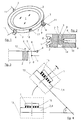
- a lens 1 is as optical element stored in an inner frame 2, which over three solid joints 3 distributed over the circumference is connected to an outer socket 4.
- Figure 2 shows a Solid-state joint in a T-shape, with the T-beam 5 on the Top is located and runs horizontally while the T-pillar 6 runs vertically.
- the solid-state joints 3 only approximately or in principle a T-shape, with connection points 7 and 8 between the inner frame 2 and the outer socket 4 at the outer ends of the T-beam 5 are located.
- a manipulator 9 In the area of the lower end of each T-pillar 6 attacks a manipulator 9, not shown, which in the outer socket 4 is mounted.
- a lever arm 10 of the manipulator 9 exerts tensile and / or compressive forces on the T-support 6 out.
- a lens is shown in principle in FIG. the in a lens or lens part 13 (only partially dashed shown) is installed, which in the installation position or later use of the center of gravity by the angle ⁇ differs.
- the lens 1 is not shown on a large number elastic feet 15 stored and thus gives a soft connection, resulting in a tilt like this is shown in the top view, namely the inclined position. By activating the corresponding manipulator (s) 9 this tilt can then be canceled or the lens 1 again return to their original reference position.
- FIG. 1 is only shown in principle how to e.g. by a capacitive sensor 16, which is in a recess 17 between the inner frame 2 and the outer frame 4 can determine the position.
- a capacitive sensor 16 which is in a recess 17 between the inner frame 2 and the outer frame 4 can determine the position.
Landscapes
- Physics & Mathematics (AREA)
- General Physics & Mathematics (AREA)
- Optics & Photonics (AREA)
- Lens Barrels (AREA)
- Exposure Of Semiconductors, Excluding Electron Or Ion Beam Exposure (AREA)
- Exposure And Positioning Against Photoresist Photosensitive Materials (AREA)
Applications Claiming Priority (2)
| Application Number | Priority Date | Filing Date | Title |
|---|---|---|---|
| DE10051706A DE10051706A1 (de) | 2000-10-18 | 2000-10-18 | Vorrichtung zur Lagerung eines optischen Elementes |
| DE10051706 | 2000-10-18 |
Publications (3)
| Publication Number | Publication Date |
|---|---|
| EP1209501A2 true EP1209501A2 (fr) | 2002-05-29 |
| EP1209501A3 EP1209501A3 (fr) | 2003-08-27 |
| EP1209501B1 EP1209501B1 (fr) | 2005-11-23 |
Family
ID=7660240
Family Applications (1)
| Application Number | Title | Priority Date | Filing Date |
|---|---|---|---|
| EP01118867A Expired - Lifetime EP1209501B1 (fr) | 2000-10-18 | 2001-08-16 | Dispositif pour l'assemblage d'un élément optique |
Country Status (4)
| Country | Link |
|---|---|
| US (1) | US6580570B2 (fr) |
| EP (1) | EP1209501B1 (fr) |
| JP (1) | JP4146632B2 (fr) |
| DE (2) | DE10051706A1 (fr) |
Cited By (2)
| Publication number | Priority date | Publication date | Assignee | Title |
|---|---|---|---|---|
| WO2003016976A3 (fr) * | 2001-08-18 | 2003-11-20 | Zeiss Carl Smt Ag | Dispositif d'ajustage d'un element optique |
| CN113167983A (zh) * | 2018-11-29 | 2021-07-23 | 卡尔蔡司Smt有限责任公司 | 用于半导体光刻的具有半主动间隔件的投射曝光设备的模块以及使用该半主动间隔件的方法 |
Families Citing this family (34)
| Publication number | Priority date | Publication date | Assignee | Title |
|---|---|---|---|---|
| DE10030495A1 (de) * | 2000-06-21 | 2002-01-03 | Zeiss Carl | Verfahren zum Verbinden einer Vielzahl von optischen Elementen mit einem Grundkörper |
| DE10136387A1 (de) * | 2001-07-26 | 2003-02-13 | Zeiss Carl | Objektiv, insbesondere Objektiv für die Halbleiter-Lithographie |
| DE10216114A1 (de) * | 2002-04-12 | 2003-10-23 | Zeiss Carl Smt Ag | Vorrichtung zur deformationsarmen Lagerung eines nicht rotationssymmetrischen optischen Elementes |
| DE10219514A1 (de) * | 2002-04-30 | 2003-11-13 | Zeiss Carl Smt Ag | Beleuchtungssystem, insbesondere für die EUV-Lithographie |
| DE10392704B4 (de) | 2002-06-04 | 2018-12-20 | Nikon Corp. | Verfahren zur Bewertung der Homogenität des Brechungsindex von optischen Bauteilen |
| DE10328972A1 (de) * | 2002-06-28 | 2004-01-22 | Carl Zeiss | Verfahren und Vorrichtung zum Ausrichten von optischen Elementen |
| DE10229623A1 (de) * | 2002-06-28 | 2004-01-15 | Carl Zeiss Jena Gmbh | Baugruppe mit einer äußeren Fassung und einem optischen Element |
| AU2003250898A1 (en) * | 2002-08-08 | 2004-03-11 | Carl Zeiss Smt Ag | Device for receiving an optical module in an imaging unit |
| DE10246828A1 (de) * | 2002-10-08 | 2004-04-22 | Carl Zeiss Smt Ag | Objektiv, insbesondere Projektionsobjektiv in der Mikrolithographie |
| DE10331390A1 (de) * | 2003-07-11 | 2005-01-27 | Carl Zeiss Smt Ag | Verfahren zur Herstellung von asphärischen optischen Flächen |
| DE10339362A1 (de) | 2003-08-27 | 2005-03-24 | Carl Zeiss Smt Ag | Vorrichtung zur Verhinderung des Kriechens eines optischen Elementes |
| US6816325B1 (en) | 2003-09-11 | 2004-11-09 | Carl Zeiss Smt Ag | Mounting apparatus for an optical element |
| DE10344178B4 (de) * | 2003-09-24 | 2006-08-10 | Carl Zeiss Smt Ag | Halte- und Positioniervorrichtung für ein optisches Element |
| US7085080B2 (en) * | 2003-12-06 | 2006-08-01 | Carl Zeiss Smt Ag | Low-deformation support device of an optical element |
| DE10359576A1 (de) * | 2003-12-18 | 2005-07-28 | Carl Zeiss Smt Ag | Verfahren zur Herstellung einer optischen Einheit |
| US7265917B2 (en) | 2003-12-23 | 2007-09-04 | Carl Zeiss Smt Ag | Replacement apparatus for an optical element |
| US7738193B2 (en) * | 2004-06-29 | 2010-06-15 | Carl Zeiss Smt Ag | Positioning unit and alignment device for an optical element |
| DE102004052155A1 (de) * | 2004-10-24 | 2006-05-04 | Berliner Elektronenspeicherring-Gesellschaft für Synchrotronstrahlung mbH | Justiervorrichtung zur hochgenauen Positionierung eines Objekts |
| DE102005015627A1 (de) | 2005-04-06 | 2006-10-12 | Carl Zeiss Smt Ag | Optische Abbildungsvorrichtung |
| DE102007030579B4 (de) * | 2006-07-21 | 2008-10-02 | Jenoptik Laser, Optik, Systeme Gmbh | Lateral verstellbare Fassung für optische Elemente |
| DE102007005203A1 (de) | 2007-01-29 | 2008-07-31 | Carl Zeiss Smt Ag | Fassung für ein optisches Element |
| DE102008041310A1 (de) | 2007-08-31 | 2009-03-05 | Carl Zeiss Smt Ag | Optisches Element |
| JP5588358B2 (ja) * | 2008-02-29 | 2014-09-10 | コーニング インコーポレイテッド | キネマティック光学マウント |
| DE102008000967B4 (de) * | 2008-04-03 | 2015-04-09 | Carl Zeiss Smt Gmbh | Projektionsbelichtungsanlage für die EUV-Mikrolithographie |
| DE102008029161B3 (de) | 2008-06-19 | 2009-10-08 | Jenoptik Laser, Optik, Systeme Gmbh | Lateral verstellbare optische Fassung mit Kniehebelmanipulatoreinheiten |
| DE102008063223B3 (de) | 2008-12-23 | 2010-09-09 | Jenoptik Laser, Optik, Systeme Gmbh | Monolithische optische Fassung |
| DE102009014972A1 (de) * | 2009-03-18 | 2010-10-14 | Carl Zeiss Laser Optics Gmbh | Optische Anordnung |
| USD636420S1 (en) * | 2010-05-06 | 2011-04-19 | Kuo-Chin Huang | Concentrator lens |
| USD649993S1 (en) * | 2010-09-17 | 2011-12-06 | Leapers, Inc. | Lens cover |
| CN102565983B (zh) * | 2011-11-18 | 2014-08-20 | 中国科学院光电技术研究所 | 一种动镜轴向微调装置 |
| CN102621651B (zh) * | 2012-03-29 | 2014-01-15 | 中国科学院光电技术研究所 | 一种动镜微调整方法 |
| DE102015115929B3 (de) * | 2015-09-21 | 2016-10-06 | Jenoptik Optical Systems Gmbh | Monolithische Linsenfassung |
| DE102015115930B3 (de) * | 2015-09-21 | 2016-11-17 | Jenoptik Optical Systems Gmbh | Versteifte Linsenfassung |
| DE102018207454A1 (de) * | 2018-05-15 | 2019-05-29 | Carl Zeiss Smt Gmbh | Aktuatoranordnung, Projektionsbelichtungsanlage und Waferinspektionsanlage für die Halbleiterlithographie |
Family Cites Families (7)
| Publication number | Priority date | Publication date | Assignee | Title |
|---|---|---|---|---|
| US3917385A (en) | 1973-09-19 | 1975-11-04 | Rockwell International Corp | Simplified micropositioner |
| DE19859634A1 (de) * | 1998-12-23 | 2000-06-29 | Zeiss Carl Fa | Optisches System, insbesondere Projektionsbelichtungsanlage der Mikrolithographie |
| DE19905779A1 (de) * | 1999-02-12 | 2000-08-17 | Zeiss Carl Fa | Vorrichtung zum Kippen eines Gegenstandes um wenigstens eine Achse, insbesondere eines optischen Elementes |
| DE19908554A1 (de) * | 1999-02-27 | 2000-08-31 | Zeiss Carl Fa | Verstellbare Baugruppe |
| DE19910947A1 (de) * | 1999-03-12 | 2000-09-14 | Zeiss Carl Fa | Vorrichtung zum Verschieben eines optischen Elementes entlang der optischen Achse |
| DE10026541A1 (de) * | 2000-05-27 | 2001-11-29 | Zeiss Carl | Vorrichtung zur präzisen Positionierung eines Bauteils, insbesondere eines optischen Bauteiles |
| DE10030005A1 (de) * | 2000-06-17 | 2001-12-20 | Zeiss Carl | Objektiv, insbesondere Projektionsobjektiv in der Halbleiter-Lithographie |
-
2000
- 2000-10-18 DE DE10051706A patent/DE10051706A1/de not_active Withdrawn
-
2001
- 2001-08-16 DE DE50108155T patent/DE50108155D1/de not_active Expired - Fee Related
- 2001-08-16 EP EP01118867A patent/EP1209501B1/fr not_active Expired - Lifetime
- 2001-10-16 JP JP2001318392A patent/JP4146632B2/ja not_active Expired - Fee Related
- 2001-10-18 US US10/002,097 patent/US6580570B2/en not_active Expired - Lifetime
Cited By (6)
| Publication number | Priority date | Publication date | Assignee | Title |
|---|---|---|---|---|
| WO2003016976A3 (fr) * | 2001-08-18 | 2003-11-20 | Zeiss Carl Smt Ag | Dispositif d'ajustage d'un element optique |
| US7193794B2 (en) | 2001-08-18 | 2007-03-20 | Carl Zeiss Smt Ag | Adjustment arrangement of an optical element |
| US7457059B2 (en) | 2001-08-18 | 2008-11-25 | Carl Zeiss Smt Ag | Adjustment arrangement of an optical element |
| US7656595B2 (en) | 2001-08-18 | 2010-02-02 | Carl Zeiss Smt Ag | Adjustment arrangement of an optical element |
| CN113167983A (zh) * | 2018-11-29 | 2021-07-23 | 卡尔蔡司Smt有限责任公司 | 用于半导体光刻的具有半主动间隔件的投射曝光设备的模块以及使用该半主动间隔件的方法 |
| CN113167983B (zh) * | 2018-11-29 | 2023-12-26 | 卡尔蔡司Smt有限责任公司 | 用于半导体光刻的具有半主动间隔件的投射曝光设备的模块以及使用该半主动间隔件的方法 |
Also Published As
| Publication number | Publication date |
|---|---|
| US20020085292A1 (en) | 2002-07-04 |
| DE10051706A1 (de) | 2002-05-02 |
| DE50108155D1 (de) | 2005-12-29 |
| JP2002139661A (ja) | 2002-05-17 |
| US6580570B2 (en) | 2003-06-17 |
| EP1209501B1 (fr) | 2005-11-23 |
| EP1209501A3 (fr) | 2003-08-27 |
| JP4146632B2 (ja) | 2008-09-10 |
Similar Documents
| Publication | Publication Date | Title |
|---|---|---|
| EP1209501A2 (fr) | Dispositif pour l'assemblage d'un élément optique | |
| EP2803528B1 (fr) | Phare de véhicule | |
| EP1035426A2 (fr) | Dispositif pour déplacer un élément optique le long de l'axe optique | |
| EP1245982A2 (fr) | Appareil pour monter un élément optique dans un appareillage optique | |
| AT516100B1 (de) | Einstellsystem für einen Fahrzeugscheinwerfer sowie Fahrzeugscheinwerfer | |
| DE29907533U1 (de) | Gerät, insbesondere Arbeitstisch für einen Projektor | |
| EP3310616B1 (fr) | Phare de véhicule avec des modules optiques ajustables | |
| DE10100546A1 (de) | Vorrichtung zur Verstellung eines optischen Elementes in einem Objektiv | |
| EP1485762A2 (fr) | Dispositif permettant de modifier la position angulaire d'un objet par rapport a une structure fixe | |
| DE4208229A1 (de) | Formeinstellbarer teleskopspiegel | |
| EP3287314A1 (fr) | Dispositif doté d'un élément adaptateur | |
| DE102008004421B3 (de) | Verfahren und Vorrichtung zum Messen des Verformungsverhaltens einer Feder | |
| EP1698996A1 (fr) | Dispositif d'identification | |
| DE3628170A1 (de) | Verstellbare praeparathalterung fuer ein korpuskularstrahlenmikroskop | |
| DE102013114822B3 (de) | Zweiachsige Kippvorrichtung | |
| DE8706688U1 (de) | Vorrichtung für die Kalibrierung von Schlauchfolienblasen | |
| DE102004014967B4 (de) | Variolinsensystem und Verfahren zu dessen Schärfenjustierung | |
| DE202004020330U1 (de) | Vorrichtung zur Überprüfung von Randbereichen flächiger Elemente | |
| DE2723323C3 (de) | Stereophotogrammetrisches Auswertegerät | |
| DE102016213784A1 (de) | Telezentrische Optikeinheit und digitales Zoommikroskop | |
| DE10136388A1 (de) | System zum Vermessen eines optischen Systems, insbesondere eines Objektives | |
| DE102008053227A1 (de) | Befestigung einer Kolben-/Zylindereinheit zur Gewichtskraftkompensation | |
| DE1750598A1 (de) | Manuell betaetigbare Einstelleinrichtung fuer eine Steuervorrichtung | |
| DE102018215321A1 (de) | Sensorkalibrierungsvorrichtung zum Einstellen von Fahrzeugsensoren eines Fahrerassistenzsystems | |
| DE102018204958B4 (de) | Anzeigeeinrichtung zur Projektion eines Bilds auf eine Scheibe eines Kraftfahrzeugs sowie Verfahren zum Betreiben einer Anzeigeeinrichtung |
Legal Events
| Date | Code | Title | Description |
|---|---|---|---|
| PUAI | Public reference made under article 153(3) epc to a published international application that has entered the european phase |
Free format text: ORIGINAL CODE: 0009012 |
|
| AK | Designated contracting states |
Kind code of ref document: A2 Designated state(s): AT BE CH CY DE DK ES FI FR GB GR IE IT LI LU MC NL PT SE TR |
|
| AX | Request for extension of the european patent |
Free format text: AL;LT;LV;MK;RO;SI |
|
| PUAL | Search report despatched |
Free format text: ORIGINAL CODE: 0009013 |
|
| AK | Designated contracting states |
Designated state(s): AT BE CH CY DE DK ES FI FR GB GR IE IT LI LU MC NL PT SE TR |
|
| AX | Request for extension of the european patent |
Extension state: AL LT LV MK RO SI |
|
| RIC1 | Information provided on ipc code assigned before grant |
Ipc: 7G 02B 7/02 A Ipc: 7G 02B 7/00 B Ipc: 7G 03F 7/20 B |
|
| 17P | Request for examination filed |
Effective date: 20031024 |
|
| 17Q | First examination report despatched |
Effective date: 20040209 |
|
| AKX | Designation fees paid |
Designated state(s): DE FR NL |
|
| RAP1 | Party data changed (applicant data changed or rights of an application transferred) |
Owner name: CARL ZEISS SMT AG |
|
| GRAP | Despatch of communication of intention to grant a patent |
Free format text: ORIGINAL CODE: EPIDOSNIGR1 |
|
| GRAS | Grant fee paid |
Free format text: ORIGINAL CODE: EPIDOSNIGR3 |
|
| GRAA | (expected) grant |
Free format text: ORIGINAL CODE: 0009210 |
|
| AK | Designated contracting states |
Kind code of ref document: B1 Designated state(s): DE FR NL |
|
| PG25 | Lapsed in a contracting state [announced via postgrant information from national office to epo] |
Ref country code: NL Free format text: LAPSE BECAUSE OF FAILURE TO SUBMIT A TRANSLATION OF THE DESCRIPTION OR TO PAY THE FEE WITHIN THE PRESCRIBED TIME-LIMIT Effective date: 20051123 |
|
| REF | Corresponds to: |
Ref document number: 50108155 Country of ref document: DE Date of ref document: 20051229 Kind code of ref document: P |
|
| NLV1 | Nl: lapsed or annulled due to failure to fulfill the requirements of art. 29p and 29m of the patents act | ||
| PLBE | No opposition filed within time limit |
Free format text: ORIGINAL CODE: 0009261 |
|
| STAA | Information on the status of an ep patent application or granted ep patent |
Free format text: STATUS: NO OPPOSITION FILED WITHIN TIME LIMIT |
|
| PG25 | Lapsed in a contracting state [announced via postgrant information from national office to epo] |
Ref country code: FR Free format text: LAPSE BECAUSE OF FAILURE TO SUBMIT A TRANSLATION OF THE DESCRIPTION OR TO PAY THE FEE WITHIN THE PRESCRIBED TIME-LIMIT Effective date: 20061020 |
|
| 26N | No opposition filed |
Effective date: 20060824 |
|
| EN | Fr: translation not filed | ||
| PGFP | Annual fee paid to national office [announced via postgrant information from national office to epo] |
Ref country code: DE Payment date: 20080822 Year of fee payment: 8 |
|
| PG25 | Lapsed in a contracting state [announced via postgrant information from national office to epo] |
Ref country code: FR Free format text: LAPSE BECAUSE OF FAILURE TO SUBMIT A TRANSLATION OF THE DESCRIPTION OR TO PAY THE FEE WITHIN THE PRESCRIBED TIME-LIMIT Effective date: 20051123 |
|
| PG25 | Lapsed in a contracting state [announced via postgrant information from national office to epo] |
Ref country code: DE Free format text: LAPSE BECAUSE OF NON-PAYMENT OF DUE FEES Effective date: 20100302 |