EP1209830A1 - Optische kommunikationsvorrichtung und optisches kommunikationsverfahren - Google Patents
Optische kommunikationsvorrichtung und optisches kommunikationsverfahren Download PDFInfo
- Publication number
- EP1209830A1 EP1209830A1 EP01925920A EP01925920A EP1209830A1 EP 1209830 A1 EP1209830 A1 EP 1209830A1 EP 01925920 A EP01925920 A EP 01925920A EP 01925920 A EP01925920 A EP 01925920A EP 1209830 A1 EP1209830 A1 EP 1209830A1
- Authority
- EP
- European Patent Office
- Prior art keywords
- light
- receipt
- transmission
- cable
- received
- Prior art date
- Legal status (The legal status is an assumption and is not a legal conclusion. Google has not performed a legal analysis and makes no representation as to the accuracy of the status listed.)
- Granted
Links
Images





Classifications
-
- H—ELECTRICITY
- H04—ELECTRIC COMMUNICATION TECHNIQUE
- H04B—TRANSMISSION
- H04B10/00—Transmission systems employing electromagnetic waves other than radio-waves, e.g. infrared, visible or ultraviolet light, or employing corpuscular radiation, e.g. quantum communication
- H04B10/40—Transceivers
- H04B10/43—Transceivers using a single component as both light source and receiver, e.g. using a photoemitter as a photoreceiver
-
- H—ELECTRICITY
- H04—ELECTRIC COMMUNICATION TECHNIQUE
- H04B—TRANSMISSION
- H04B10/00—Transmission systems employing electromagnetic waves other than radio-waves, e.g. infrared, visible or ultraviolet light, or employing corpuscular radiation, e.g. quantum communication
- H04B10/40—Transceivers
-
- G—PHYSICS
- G02—OPTICS
- G02B—OPTICAL ELEMENTS, SYSTEMS OR APPARATUS
- G02B6/00—Light guides; Structural details of arrangements comprising light guides and other optical elements, e.g. couplings
- G02B6/24—Coupling light guides
- G02B6/42—Coupling light guides with opto-electronic elements
- G02B6/4201—Packages, e.g. shape, construction, internal or external details
- G02B6/4204—Packages, e.g. shape, construction, internal or external details the coupling comprising intermediate optical elements, e.g. lenses, holograms
- G02B6/4214—Packages, e.g. shape, construction, internal or external details the coupling comprising intermediate optical elements, e.g. lenses, holograms the intermediate optical element having redirecting reflective means, e.g. mirrors, prisms for deflecting the radiation from horizontal to down- or upward direction toward a device
-
- G—PHYSICS
- G02—OPTICS
- G02B—OPTICAL ELEMENTS, SYSTEMS OR APPARATUS
- G02B6/00—Light guides; Structural details of arrangements comprising light guides and other optical elements, e.g. couplings
- G02B6/24—Coupling light guides
- G02B6/42—Coupling light guides with opto-electronic elements
- G02B6/4201—Packages, e.g. shape, construction, internal or external details
- G02B6/4246—Bidirectionally operating package structures
-
- H—ELECTRICITY
- H10—SEMICONDUCTOR DEVICES; ELECTRIC SOLID-STATE DEVICES NOT OTHERWISE PROVIDED FOR
- H10F—INORGANIC SEMICONDUCTOR DEVICES SENSITIVE TO INFRARED RADIATION, LIGHT, ELECTROMAGNETIC RADIATION OF SHORTER WAVELENGTH OR CORPUSCULAR RADIATION
- H10F55/00—Radiation-sensitive semiconductor devices covered by groups H10F10/00, H10F19/00 or H10F30/00 being structurally associated with electric light sources and electrically or optically coupled thereto
- H10F55/20—Radiation-sensitive semiconductor devices covered by groups H10F10/00, H10F19/00 or H10F30/00 being structurally associated with electric light sources and electrically or optically coupled thereto wherein the electric light source controls the radiation-sensitive semiconductor devices, e.g. optocouplers
- H10F55/26—Radiation-sensitive semiconductor devices covered by groups H10F10/00, H10F19/00 or H10F30/00 being structurally associated with electric light sources and electrically or optically coupled thereto wherein the electric light source controls the radiation-sensitive semiconductor devices, e.g. optocouplers wherein the radiation-sensitive semiconductor devices have potential barriers
Definitions
- This invention relates to an optical communication method and apparatus and, more particularly, to a method and apparatus for enabling bidirectional communication over a sole optical fiber.
- the IEEE 1394 high speed serial bus referred to below as 1394 bus
- 1394 bus a plural number of electronic equipment in a household can be interconnected to form a household network.
- a preset bit error rate (BER) is to be realized, it is necessary to provide for a preset signal to noise ratio (S/N ratio).
- S/N ratio signal to noise ratio
- a system shown for example, in Fig. 1 is usually presupposed. In this system, if the volume of light transmitted using the optical fiber is at a level H or at a level L, such states are verified to be a logical level H and a logical level L, respectively.
- the amount of light received is changed analogically, so that, with a median decision level between the level H and the level L (H+L)/2 being a decision level D, the state of the volume of the received light being larger than D and the state of the volume of the received light being smaller than D are verified to be the logical 1 and the logical 0, respectively.
- bit error rate BER was calculated from the following equations, assuming that a Gaussian noise was superposed on each of the levels H and L:
- BER is calculated as a ratio to the entire area of an area where the skirts of the Gaussian distribution of the level H overlap with those of the level L.
- bit error rate BE bit error rate
- Q value Q-value
- the full duplex communication means the communication employing substantially the same wavelength for both the transmitting and receiving sides to effect light propagation for transmission and that for reception simultaneously.
- the light of a preset wavelength is generated from a light transmitting device 2 of an equipment 1 so as to be transmitted over an optical fiber 21 to an equipment 2 for reception by a light receiving device 13 of the equipment 2.
- a light emitting device 12 of the equipment 2 emits light of substantially the same wavelength as that of the light generated by the light transmitting device 2 and transmitted over the optical fiber 21 for reception by a light receiving device 3 of the equipment 1.
- the equipment 1 If, on the side equipment 1, the light receiving device 3 receives only the light generated by the light emitting device 12 of the equipment 2, the equipment 1 is able to perform transmission/reception substantially simultaneously as the equipment 2.
- the S/N ratio is 5 (10/2).
- the optical system 31 is basically configured as shown in Fig. 6.
- the opposite side optical system 41 is similarly configured, as shown in Fig.6.
- This optical system 31 includes a prism 52 on a substrate 51.
- the light radiated from the light emitting device 2 is reflected by a surface 52A of the prism 52 and introduced through a lens 53 into the inside of the optical fiber 21 via end face 21A thereof so as to be transmitted to the side equipment 2.
- the light transmitted from the equipment 2 is radiated from the end face 21A of the optical fiber 21 to fall on an end face 52A of the prism 52 through lens 53 and is transmitted through the prism to fall on the light receiving device 3 formed on the substrate 51.
- the optical systems 31, 41 configured as described above, separate the light for transmission, radiated from the light emitting device 12 and the light for reception transmitted from the optical fiber 21, by the prism 52.
- part of light radiated from the light emitting device 12 is not reflected from the surface 52A of the prism 52, but is introduced into the inside of the prism 52, so as to be received by the light receiving device 3.
- the processing for transmission and that for reception are carried out time-divisionally, as shown in the flowcharts of Figs.7 and 8.
- step S1 the equipment 1 at step S1 verifies whether or not there is data for transmission. If there is no data for transmission, processing transfers to step S2 to check whether or not a use request signal for a line (optical fiber 21) has been received from the equipment 2. If there is no line use request signal from the equipment 2, processing reverts to step S to repeat the subsequent processing.
- step S2 If it is verified at step S2 that the line use request signal has been received from the equipment, processing transfers to step S3 where the equipment 1 sets the reception mode.
- step S4 it is verified whether or not a signal is being received from the equipment 2. That is, it is checked whether or not the line use request signal is being still received. If the signal is being received, waiting state is set until the signal ceases to be received. When the signal ceases to be received, processing transfers to step S5 where the equipment 1 advises the equipment 2 of the effect of setting of the reception mode.
- step S6 If this notification is made, data is transmitted from the equipment 2, as will be explained subsequently. Then, the waiting mode is set at step S6 until data is received. On reception of the data, it is stored e.g., in a memory at step S7. At step S8, it is verified whether or not a data end signal is received and, if no signal has been received, processing reverts to step S6 to repeat subsequent steps.
- step S8 processing transfers to step S9 where the equipment 1 cancels the reception mode to revert to step S1 to repeat the subsequent steps.
- step S10 If it is verified at step S1 that transmission data exist, processing transfers to step S10 where the equipment 1 outputs a line use request signal to the equipment 2.
- step S11 the equipment 1 verifies whether or not reception mode setting notification has been received from the equipment 2. If the reception mode setting notification has been received, processing transfers to step S12 where the equipment 1 sets the transmission mode.
- step S13 the equipment 1 sends data and, at step S14, it verifies whether or not data transmission has come to a close. If data transmission has come to a close, processing reverts to step S13 and, if otherwise, the processing reverts to step S13 to repeat subsequent steps.
- step S14 If it is verified at step S14 that data transmission has come to a close, processing transfers to step S15 where the equipment outputs a data end signal to the equipment 2. At step S16, the equipment 1 cancels the transmission mode. Then, processing reverts to step S to repeat subsequent steps.
- step S11 If it is verified at step S11 that the reception mode setting notification has not been received from the equipment 2, it may be conjectured that, at a timing of outputting the line use request signal at step S10 from the equipment 1 to the equipment 2, a line use request signal is also issued from the equipment 1, such that the two line use request signals overlap with each other with the result the equipment 2 has failed to receive the line use request signal output by the equipment 1.
- processing transfers to step S17 where the equipment 2 verifies whether or not the line use request signal has again been received. If the line use request signal has not been received, processing transfers to step S18 to verify whether or not a preset random time has elapsed since the outputting of the line use request signal. If this preset random time has not elapsed, processing reverts to step S17 to execute subsequent steps repeatedly.
- step S18 If it is verified at step S18 that the preset random time has elapsed, processing reverts to step S1 to execute subsequent steps repeatedly.
- the equipment 2 executes the processing of queuing until a preset random time elapses. In general, this preset random time is different from the preset random time as set for the equipment 1. If the preset time for the equipment I is longer than that for the equipment 2, the equipment 2 again sends a line use request signal when the equipment is at a standby state. In such case, the line use request signal is deemed to have been received at step S17, so that processing transfers to step S3 to execute the processing similar to that described above.
- transmission processing is initiated independently from both the equipment 1 and 2 and, failing a proper response from the counterpart side, the random standby state is set for both equipment to permit similar processing to be re-executed. Since this random time for the two equipment is usually different, the equipment with the shorter time setting is the first to transmit data.
- the present invention provides an optical communication apparatus in which light for transmission and light for receipt are propagated simultaneously over a sole cable to effect bidirectional communication, including light emitting means for emitting the light for transmission, light receipt means for receiving the light for receipt and light guide means for guiding the light for transmission over the cable and for guiding the light for receipt to the light receipt means, wherein the value of a light volume M of stray light generated with respect to the light receipt means is set to satisfy the following relationship: S - 2QN ⁇ M > S/2Q - N where Q is the value of a Q-value representing the communication quality as required, S is the light volume of a received signal from a communication partner and N is the sum total of the Gaussian noise.
- the ratio S/M, where S is the light volume of the received signal and M is the light volume of the stray light may be set to 7% to 30%.
- the transmission speed in the optical communication may be not lower than 100 Mbps.
- the cable may be a plastic optical fiber.
- the sum of light volumes of the reflected light from the communication partner may be 0.7% to 3.0% of the volume of the received light in the communication partner.
- the present invention also provides an optical communication method by an optical communication apparatus including light emitting means for emitting the light for transmission, light receipt means for receiving the light for receipt and light guide means for guiding the light for transmission over the cable and for guiding the light for receipt to the light receipt means, the light for transmission and the light for receipt of substantially the same wavelength being propagated substantially simultaneously by a sole cable to effect bidirectional communication, wherein the value of a light volume M of stray light generated with respect to the light receipt means is set to satisfy the following relationship: S - 2QN ⁇ M > S/2Q - N where Q is the value of a Q-value representing the communication quality as required, S is the light volume of a received signal from a communication partner and N is the sum total of the Gaussian noise.
- the present invention also provides an optical communication apparatus in which the light for transmission and light for receipt of substantially the same wavelength are propagated simultaneously over a sole cable to effect bidirectional communication, including light emitting means for emitting the light for transmission, light receipt means for receiving the light for receipt and light guide means for guiding the light for transmission over the cable and for guiding the light for receipt to the light receipt means, and controlling means for controlling the light emitting means and the light receipt means, the controlling means allowing for processing of a signal corresponding to the light for receipt received by the light receipt means in a state in which the light for transmission is emitted by the light emitting means and propagated over the cable, the controlling means allowing for processing for transmission of a signal by the light for transmission emitted by the light emitting means in a state in which the light for receipt propagated over the cable is being received by the light receipt means.
- the present invention also provides an optical communication method for an optical communication apparatus including light emitting means for emitting the light for transmission, light receipt means for receiving the light for receipt and light guide means for guiding the light for transmission to the cable and for guiding the light for receipt to the light receipt means, in which light for transmission and light for receipt of substantially the same wavelength are propagated simultaneously over a sole cable to effect bidirectional communication, in which the optical communication method includes allowing for processing of a signal corresponding to the light for receipt received by the light receipt means in a state in which the light for transmission is emitted by the light emitting means and propagated over the cable, and allowing for processing for transmission of a signal by the light for transmission emitted by the light emitting means in a state in which the light for receipt propagated over the cable is being received by the light receipt means.
- processing of a signal corresponding to the light for receipt as received is allowed in a state in which light for transmission is radiated and propagated over a cable, while processing for transmission of the signal by the light for transmission emitted is allowed in a state in which the light for receipt propagated over the cable is received.
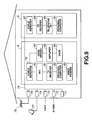
- Fig.9 shows an illustrative structure of a bus system embodying the present invention.
- terminals 71 to 75 and electronic equipment in rooms A and B are interconnected over a plastic optical fiber 76.
- a network of B_ISDN and a network of CATV are connected, respectively.
- a parabola antenna 77 for receiving electrical waves transmitted over a broadcast satellite or a communication satellite.
- an antenna 78 for receiving electrical waves of television broadcast of ground waves.
- a cable repeater 79 is mounted and connected to a plastic optical fiber 76.
- an I RD 80, a television receiver 81, a personal computer 82 and a video printer 83 are connected over the connected plastic optical fiber 76, and a home server 84, an amplifier 85 and a DVCR 86 are also connected.
- a cable repeater 87 of the room B To a cable repeater 87 of the room B is connected the plastic optical fiber 76. To the cable repeater 87, a television receiver 88, a telephone set 89 and a personal computer 90 are also connected over this plastic optical fiber 76.
- optical fiber 76 The equipment and terminals, connected to the plastic optical fiber 76, which will be hereinafter referred as an optical fiber 76, are provided with a built-in interface, configured as shown in Fig.10, for executing optical communication over the optical fiber 76.
- the end of the optical fiber 76 is connected to a plug 135 mounted in a receptacle 134.
- An optical system 133 is mounted facing the receptacle 134.
- the light propagated through the inside of the optical fiber 76 falls on the optical system 133 through plug 135 and receptacle 134 so as to be supplied from the optical system 133 to a light receiving device 136.
- the electrical signals corresponding to the amount of received light, output by the light receiving device 136, are converted by a preamplifier 137 from the electrical current to an electrical voltage.
- a waveform shaping/binary coding circuit 138 wavefonn shapes and binary encodes the voltage signals supplied from the preamplifier 137 to output the resulting voltage signals to a receipt circuit 123.
- the transmission signal, output by a transmission circuit 121, are input to a light emitting driver circuit 131 of a transceiver circuit 122.
- the light emitting driver circuit 131 is responsive to an input signal to drive a light emitting device 132.
- the light emitting device 132 is responsive to the input signal to emit light, which then is routed through receptacle 134 and plug 135 to the optical fiber 76 and thence propagated to other equipment through the inside of the optical fiber 76.
- a control circuit 124 comprised of e.g., a micro-computer, captures and processes data received by the receipt circuit 123 to send the processed transmission data to a transmission circuit 121.
- the control circuit 124 controls the transceiver circuit 122 in cooperation with the transmission circuit 121 and the receipt circuit 123 to control the transmission/reception operations.
- Fig.11 shows an illustrative structure of the optical system 133.
- the light radiated from the light emitting device 132 such as a laser diode or an LED, falls on a coupling lens 142 mounted on a base 142A provided on a semiconductor substrate 141.
- the optical axis of the coupling lens 142 is offset a distance d from the center of strength of light emitted by the light emitting device 132.
- the traveling path of the center of intensity of light radiated from the light emitting device 132 (main light beam) is bent upwards in Fig.11 and is further totally reflected by a total reflection surface 143A of a light path raising mirror 143 mounted on the semiconductor substrate 141 so as to fall as light L1 on an end face 76A ofthe optical fiber 76 at an angle ⁇ .
- the light L1 incident on the end face 76A is introduced into the bulk of the optical fiber 76 for propagation towards other equipment.
- a part of the light L1, reflected by the end face 76A of the optical fiber 76 is illuminated as light L3 on the semiconductor substrate 141.
- the light receiving device 136 formed e.g., by a photodiode, is mounted at such a position on which light L3 is not incident and also on which the light transmitted from another equipment and radiated from the end face 76A of the optical fiber 76 is incident. As a result, the light receiving device 136 receives light from other equipment, but does not receive the light L3, as stray light, reflected by the end face 76A.
- This effect can be realized by selecting the angle of the end face 76A of the optical fiber 76 or the degree of convergence (effective NA) of the light L3 to preset values.
- stray light is not thought of as a noise component in the Gaussian distribution, but is thought of as signal deterioration. That is, the waveform of a signal following current-to-voltage conversion by the preamplifier 137 of the output of the light receiving device 136 in case the amount of the stray light is 10% (see Fig.12) and 30% (see Fig.13) is as shown in Figs.12 and 13.
- the stray light components are thought of as existing stationarily in a certain proportion with respect to signals but not exhibiting so-called Gaussian distribution to gradually deteriorate the signal over a wide range. This may be understood from the fact that the eye pattern of Figs.12 and 13 is not blurred out in its entirety but simply become unclear only in an area lying outside a preset contour, with the inside of the contour remaining clear.
- the stray light in the present invention exists as components increasing the levels of logical 0 and 1 by preset levels, as shown in Fig.14.
- the noise exhibiting the Gaussian distribution exist respectively for the logical levels of 1 and 0 or relative to the stray light M.
- the S/N ratio (S-M)/N.
- the present inventors conducted experiments using a system shown in Fig.15.
- pulses were generated by a pulse generator 165 to drive a laser diode 166.
- the laser light radiated from the laser diode 166 is incident through lens 167 and ND filter 168 on a half-mirror 164.
- the laser light reflected by the half-mirror 164 falls on a multi-mode silicon fiber 169 and propagated therethrough so as to be incident through lens 170 on a photodiode 171.
- a pulse generator 165 is used to generate signals serving as stray light components for driving a laser diode 162.
- the laser light radiated from the laser diode 162 falls through lens 163 on the half mirror 164 so as to be synthesized with the laser light as signal component.
- a digital oscilloscope 172 is used to observe changes in light volume received by photodiode 171 and an error detector 173 compares the pulses (clocks) output by a pulse generator 165 with the results observed by the digital oscilloscope 172 to detect an error.
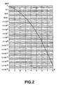
- the proportion of stray light when the bit error rate of 1E-9 is approximately 31%, while the proportion of the stray light when the 1E-12 bit error rate is obtained is approximately 23%.
- the calculated value differs significantly from the experimental value, whereas the calculated value substantially coincides with the experimental value. This testifies to the correctness of the notion of the present invention that the stray light is to be conceived as signal deterioration rather than as the noise exhibiting the Gaussian distribution.
- the light emitting device 132 may, for example, be a laser diode or LED, the wavelength of which is in the vicinity of 650 run, while its RIN (relative noise intensity) may be not larger than -115 dB/Hz.
- a PIN photodiode of silicon may be used as the light receiving device 136.
- an optical fiber 76 a plastic optical fiber of StepIndex formed by PMMA may be used. If a signal is to be modified with duty 50% by the light emitting driver circuit 131, the amount of transmitted light may be -2.7 dBm to -9.9 dBm in terms of an average power.
- the light volume loss in this transmission system is assumed to be 5 dB at the maximum, in view of transmission loss, bending loss and end face loss.
- the amount of reflection at an end face of a communication partner on the optical fiber 76 (amount of reflection at the distal end) and the receipt efficiency are assumed to be 1.4% at the maximum and -3 dB, respectively.
- the sum of the stray light at the distal end and that at the proximal end is -25.1 dBm.
- the sum of the received light volume at the distal end and at the proximal end is -27.4 dBm.
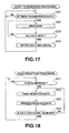
- step S31 the control circuit 124 checks whether or not transmission data exist. If it is verified that there exist no transmission data, the control circuit 124 is at a standby state until transmission data is produced.
- step S31 If, at step S31, it is verified that these exist transmission data, processing transfers to step S32 where the control circuit 124 executes the processing of sending the data.
- the control circuit 124 then outputs transmission data to the transmission circuit 121, which then modulates the transmission data in accordance with a preset system to send the modulated data to the light emitting driver circuit 131 of the transceiver circuit 122.
- the light emitting driver circuit 131 drives the light emitting device 132 based on the transmission data input from the transmission circuit 121. As a result, the light emitting device 132 generates light corresponding to the transmission data.
- This light is incident through a coupling lens 142 to a total reflection surface 143A of a light path raising mirror 143 where the incident light is totally reflected so as to be introduced from the end face 76A into the inside of the optical fiber 76 for transmission to the equipment of the communication partner.
- step S33 the control circuit 124 verifies whether or not the totality of data have been received. If there is any data not as yet transmitted, processing reverts to step S32 to repeat the similar processing.
- step S34 If it is verified at step S33 that the totality of data have been transmitted, processing transfers to step S34 where the control circuit 124 outputs a data end signal which is sent to the communication partner as routine communication data. On receipt of the data end signal, the communication partner is able to detect the end of data transmitted. Then, processing reverts to step S31 to repeat subsequent processing.
- step S51 the control circuit 124 verifies whether or not the data has been received. If the data has not been received, the control circuit 124 is in a stand-by state until the data is received. If it has been verified at step S51 that the data has been received, processing transfers to step S52 where the control circuit 124 undertakes the processing to take the reception data.
- the light propagated on the optical fiber 76 is radiated from the end face 76A to fall on the face 136A of the light receiving device 136 on the semiconductor substrate 141.
- the light receiving device 136 outputs a signal corresponding to the volume of the incident light.
- This signal is converted by the preamplifier 137 from the current to the voltage and sent to the waveform shaping/binary coding circuit 138.
- This waveform shaping/binary coding circuit 138 waveforms shapes and binary-codes the input voltage signal to route the resulting signal to the receipt circuit 123.
- the receipt circuit 123 demodulates the received data for storage in an enclosed memory.
- step S53 processing transfers to step S53 where the control circuit 124 undertakes to process the received data.
- the control circuit 124 controls the receipt circuit 123 to receive data to process the stored data.
- the receipt circuit 123 corrects the received data for errors to route the received data to the control circuit 124.
- step S54 the control circuit 124 checks whether or not the data end signal has been received. If the data end signal has not been received, processing reverts to step S52 to repeat subsequent processing.
- step S54 If it is verified at step S54 that the data end signal has been received, the control circuit 124 deems that the processing of data transmission from the communication partner has come to a close to terminate the receipt processing. Then, processing reverts to step S51 to repeat the subsequent processing.
- the control circuit 124 undertakes to execute the transmission processing shown in Fig.17 and the receipt processing shown in Fig.18 independently of each other. In other words, it allows for receipt processing as transmission processing is continued, while allowing for transmission processing as receipt processing is continued. By so doing, the control circuit 124 is able to transmit and receive data at an optional timing.
- the equipment connected to the optical fiber 76 is able to transmit and receive data promptly.
- the value of the light volume M in the light reception means is set such as to satisfy the following equation: S - 2QN ⁇ M > S/2Q - N it is possible to send the light for transmission and the light for receipt of substantially the same wavelength simultaneously on the routine cable to effect communication bidirectionally. As a result, both the weight and the production cost can be reduced as compared with an instance in which two cables are used.
- the present invention in which, when the light for transmission is emitted by light emitting means and propagated over a cable, signal processing is allowed for the light for receipt received by light receiving means, whereas, when the light for receipt propagated over a cable is received by light receiving means, signal processing is allowed for the light for transmission emitted by light emitting means, it is possible to have the light for transmission and the light for receipt propagated simultaneously through a sole cable to perform bidirectional communication.
Landscapes
- Physics & Mathematics (AREA)
- General Physics & Mathematics (AREA)
- Optics & Photonics (AREA)
- Electromagnetism (AREA)
- Engineering & Computer Science (AREA)
- Computer Networks & Wireless Communication (AREA)
- Signal Processing (AREA)
- Optical Communication System (AREA)
- Optical Couplings Of Light Guides (AREA)
Applications Claiming Priority (3)
| Application Number | Priority Date | Filing Date | Title |
|---|---|---|---|
| JP2000129077 | 2000-04-28 | ||
| JP2000129077 | 2000-04-28 | ||
| PCT/JP2001/003584 WO2001084751A1 (en) | 2000-04-28 | 2001-04-25 | Optical communication apparatus and communication method |
Publications (3)
| Publication Number | Publication Date |
|---|---|
| EP1209830A1 true EP1209830A1 (de) | 2002-05-29 |
| EP1209830A4 EP1209830A4 (de) | 2006-10-18 |
| EP1209830B1 EP1209830B1 (de) | 2010-03-03 |
Family
ID=18638408
Family Applications (1)
| Application Number | Title | Priority Date | Filing Date |
|---|---|---|---|
| EP01925920A Expired - Lifetime EP1209830B1 (de) | 2000-04-28 | 2001-04-25 | Optische kommunikationsvorrichtung und optisches kommunikationsverfahren |
Country Status (10)
| Country | Link |
|---|---|
| US (1) | US7072583B2 (de) |
| EP (1) | EP1209830B1 (de) |
| JP (1) | JP3825322B2 (de) |
| KR (1) | KR100798514B1 (de) |
| CN (1) | CN1297087C (de) |
| AT (1) | ATE460018T1 (de) |
| AU (1) | AU5258001A (de) |
| DE (1) | DE60141445D1 (de) |
| TW (1) | TWI230815B (de) |
| WO (1) | WO2001084751A1 (de) |
Cited By (1)
| Publication number | Priority date | Publication date | Assignee | Title |
|---|---|---|---|---|
| WO2009007948A1 (en) * | 2007-07-11 | 2009-01-15 | Eci Telecom Ltd | Technique for securing transmission of data along an optical communication line |
Families Citing this family (6)
| Publication number | Priority date | Publication date | Assignee | Title |
|---|---|---|---|---|
| JP3842145B2 (ja) * | 2002-02-21 | 2006-11-08 | シャープ株式会社 | 通信装置及び通信システム |
| JP4112260B2 (ja) | 2002-04-04 | 2008-07-02 | シャープ株式会社 | 光通信システムの製造方法 |
| US20080037989A1 (en) * | 2006-08-14 | 2008-02-14 | Paul Douglas Stoner | Method And Apparatus For Handling Data And Aircraft Employing Same |
| US20080089087A1 (en) * | 2006-10-16 | 2008-04-17 | Paul Douglas Stoner | Apparatus and Method Pertaining to Light-Based Power Distribution in a Vehicle |
| JP6099114B2 (ja) * | 2011-06-14 | 2017-03-22 | ローム株式会社 | 無線伝送装置 |
| CN103310509B (zh) * | 2012-03-15 | 2016-12-14 | 深圳光启智能光子技术有限公司 | 一种门禁系统的通信方法 |
Family Cites Families (9)
| Publication number | Priority date | Publication date | Assignee | Title |
|---|---|---|---|---|
| JPH0591049A (ja) | 1991-09-25 | 1993-04-09 | Nec Corp | 光回路 |
| JPH05268170A (ja) | 1992-03-18 | 1993-10-15 | Fujikura Ltd | 光ファイバ通話装置 |
| JPH06244805A (ja) * | 1993-02-17 | 1994-09-02 | Sony Corp | 光信号伝送装置 |
| JPH08234063A (ja) * | 1994-12-19 | 1996-09-13 | Sony Corp | 送受信光モジュール |
| JPH08234061A (ja) * | 1995-02-24 | 1996-09-13 | Kyocera Corp | 光通信用モジュール |
| JPH10242918A (ja) | 1997-02-28 | 1998-09-11 | Fujikura Ltd | 光ファイバ1心双方向通信装置 |
| JPH11237535A (ja) * | 1997-12-16 | 1999-08-31 | Sony Corp | 光送受信装置及び光送受信方法 |
| JP3399832B2 (ja) * | 1998-04-20 | 2003-04-21 | シャープ株式会社 | 双方向光通信器および双方向光通信装置 |
| JPH11352364A (ja) | 1998-06-10 | 1999-12-24 | Sony Corp | 光送受信装置と光送受信方法 |
-
2001
- 2001-04-25 AU AU52580/01A patent/AU5258001A/en not_active Abandoned
- 2001-04-25 DE DE60141445T patent/DE60141445D1/de not_active Expired - Lifetime
- 2001-04-25 AT AT01925920T patent/ATE460018T1/de not_active IP Right Cessation
- 2001-04-25 JP JP2001581453A patent/JP3825322B2/ja not_active Expired - Fee Related
- 2001-04-25 US US10/019,332 patent/US7072583B2/en not_active Expired - Fee Related
- 2001-04-25 WO PCT/JP2001/003584 patent/WO2001084751A1/ja not_active Ceased
- 2001-04-25 CN CNB018018254A patent/CN1297087C/zh not_active Expired - Fee Related
- 2001-04-25 KR KR1020017016702A patent/KR100798514B1/ko not_active Expired - Fee Related
- 2001-04-25 EP EP01925920A patent/EP1209830B1/de not_active Expired - Lifetime
- 2001-04-26 TW TW090110027A patent/TWI230815B/zh not_active IP Right Cessation
Cited By (2)
| Publication number | Priority date | Publication date | Assignee | Title |
|---|---|---|---|---|
| WO2009007948A1 (en) * | 2007-07-11 | 2009-01-15 | Eci Telecom Ltd | Technique for securing transmission of data along an optical communication line |
| US8218966B2 (en) | 2007-07-11 | 2012-07-10 | Eci Telecom Ltd. | Technique for securing transmission of data along an optical communication line |
Also Published As
| Publication number | Publication date |
|---|---|
| DE60141445D1 (de) | 2010-04-15 |
| CN1297087C (zh) | 2007-01-24 |
| US7072583B2 (en) | 2006-07-04 |
| US20030025958A1 (en) | 2003-02-06 |
| CN1383639A (zh) | 2002-12-04 |
| WO2001084751A1 (en) | 2001-11-08 |
| EP1209830A4 (de) | 2006-10-18 |
| KR20020048310A (ko) | 2002-06-22 |
| AU5258001A (en) | 2001-11-12 |
| ATE460018T1 (de) | 2010-03-15 |
| JP3825322B2 (ja) | 2006-09-27 |
| TWI230815B (en) | 2005-04-11 |
| EP1209830B1 (de) | 2010-03-03 |
| KR100798514B1 (ko) | 2008-01-28 |
Similar Documents
| Publication | Publication Date | Title |
|---|---|---|
| KR970003526B1 (ko) | 정보 전송 장치와 방법 및 컴퓨터 상호 접속용 통신 매체 | |
| EP1209830A1 (de) | Optische kommunikationsvorrichtung und optisches kommunikationsverfahren | |
| US5073000A (en) | Optical interconnect printed circuit structure | |
| US6973105B2 (en) | Method and apparatus to enable adaptive equalization at high bandwidths when using single-mode VCSELs over multimode fibers | |
| JPWO2001084751A1 (ja) | 光通信装置及び通信方法 | |
| CN107171726A (zh) | 短距无线信息传输方法及移动终端 | |
| US4859015A (en) | Optical receiver having optical gain medium and mode selector | |
| KR100818233B1 (ko) | 쌍방향 통신을 위해 사용되는 광섬유에서 광신호 반사의 효과를 감소시키는 방법 | |
| CN107121738A (zh) | 光模块 | |
| US20050129367A1 (en) | Method and apparatus for angled fiber optical attenuation | |
| EP1168677A2 (de) | Optische Datenbuskommunikation in einem künstlichen Satelliten | |
| JP4112260B2 (ja) | 光通信システムの製造方法 | |
| JP2546171B2 (ja) | 反射光消去形光送受信回路 | |
| Younus et al. | Subcarrier multiplexing for parallel data transmission in indoor visible light communication systems | |
| JP3830376B2 (ja) | 送信ユニット | |
| CN210864120U (zh) | 一种高度可控收发同侧光组件 | |
| JPS5933942A (ja) | 光デ−タ伝送システム | |
| JP2002084236A (ja) | 単芯双方向光通信システム | |
| Kim et al. | Centralized optical backplane with energy equalized fan-outs for board-to-board interconnections | |
| JPH07106699A (ja) | 光伝送装置 | |
| JP2001077764A (ja) | 光信号伝送装置 | |
| JPS60140941A (ja) | 光空間伝送方式 | |
| JPH0429427A (ja) | 双方向光伝送装置 | |
| JPH04216224A (ja) | 光送信装置 | |
| JP2003060586A (ja) | 光通信装置およびそれにおける受信波形の位相余裕確保方法 |
Legal Events
| Date | Code | Title | Description |
|---|---|---|---|
| PUAI | Public reference made under article 153(3) epc to a published international application that has entered the european phase |
Free format text: ORIGINAL CODE: 0009012 |
|
| 17P | Request for examination filed |
Effective date: 20020212 |
|
| AK | Designated contracting states |
Kind code of ref document: A1 Designated state(s): AT BE CH CY DE DK ES FI FR GB GR IE IT LI LU MC NL PT SE TR |
|
| AX | Request for extension of the european patent |
Free format text: AL;LT;LV;MK;RO;SI |
|
| RIC1 | Information provided on ipc code assigned before grant |
Ipc: H01L 31/12 20060101ALI20011115BHEP Ipc: H04B 10/24 20060101AFI20060628BHEP Ipc: G02B 6/42 20060101ALI20011115BHEP |
|
| A4 | Supplementary search report drawn up and despatched |
Effective date: 20060920 |
|
| 17Q | First examination report despatched |
Effective date: 20070820 |
|
| GRAP | Despatch of communication of intention to grant a patent |
Free format text: ORIGINAL CODE: EPIDOSNIGR1 |
|
| GRAS | Grant fee paid |
Free format text: ORIGINAL CODE: EPIDOSNIGR3 |
|
| GRAA | (expected) grant |
Free format text: ORIGINAL CODE: 0009210 |
|
| AK | Designated contracting states |
Kind code of ref document: B1 Designated state(s): AT BE CH CY DE DK ES FI FR GB GR IE IT LI LU MC NL PT SE TR |
|
| REG | Reference to a national code |
Ref country code: GB Ref legal event code: FG4D |
|
| REG | Reference to a national code |
Ref country code: CH Ref legal event code: EP |
|
| REG | Reference to a national code |
Ref country code: IE Ref legal event code: FG4D |
|
| REF | Corresponds to: |
Ref document number: 60141445 Country of ref document: DE Date of ref document: 20100415 Kind code of ref document: P |
|
| REG | Reference to a national code |
Ref country code: SE Ref legal event code: TRGR |
|
| REG | Reference to a national code |
Ref country code: NL Ref legal event code: VDEP Effective date: 20100303 |
|
| PG25 | Lapsed in a contracting state [announced via postgrant information from national office to epo] |
Ref country code: FI Free format text: LAPSE BECAUSE OF FAILURE TO SUBMIT A TRANSLATION OF THE DESCRIPTION OR TO PAY THE FEE WITHIN THE PRESCRIBED TIME-LIMIT Effective date: 20100303 Ref country code: AT Free format text: LAPSE BECAUSE OF FAILURE TO SUBMIT A TRANSLATION OF THE DESCRIPTION OR TO PAY THE FEE WITHIN THE PRESCRIBED TIME-LIMIT Effective date: 20100303 |
|
| PG25 | Lapsed in a contracting state [announced via postgrant information from national office to epo] |
Ref country code: BE Free format text: LAPSE BECAUSE OF FAILURE TO SUBMIT A TRANSLATION OF THE DESCRIPTION OR TO PAY THE FEE WITHIN THE PRESCRIBED TIME-LIMIT Effective date: 20100303 Ref country code: NL Free format text: LAPSE BECAUSE OF FAILURE TO SUBMIT A TRANSLATION OF THE DESCRIPTION OR TO PAY THE FEE WITHIN THE PRESCRIBED TIME-LIMIT Effective date: 20100303 Ref country code: GR Free format text: LAPSE BECAUSE OF FAILURE TO SUBMIT A TRANSLATION OF THE DESCRIPTION OR TO PAY THE FEE WITHIN THE PRESCRIBED TIME-LIMIT Effective date: 20100604 Ref country code: ES Free format text: LAPSE BECAUSE OF FAILURE TO SUBMIT A TRANSLATION OF THE DESCRIPTION OR TO PAY THE FEE WITHIN THE PRESCRIBED TIME-LIMIT Effective date: 20100614 Ref country code: CY Free format text: LAPSE BECAUSE OF FAILURE TO SUBMIT A TRANSLATION OF THE DESCRIPTION OR TO PAY THE FEE WITHIN THE PRESCRIBED TIME-LIMIT Effective date: 20100303 |
|
| PG25 | Lapsed in a contracting state [announced via postgrant information from national office to epo] |
Ref country code: MC Free format text: LAPSE BECAUSE OF NON-PAYMENT OF DUE FEES Effective date: 20100430 |
|
| REG | Reference to a national code |
Ref country code: CH Ref legal event code: PL |
|
| PLBE | No opposition filed within time limit |
Free format text: ORIGINAL CODE: 0009261 |
|
| STAA | Information on the status of an ep patent application or granted ep patent |
Free format text: STATUS: NO OPPOSITION FILED WITHIN TIME LIMIT |
|
| PG25 | Lapsed in a contracting state [announced via postgrant information from national office to epo] |
Ref country code: PT Free format text: LAPSE BECAUSE OF FAILURE TO SUBMIT A TRANSLATION OF THE DESCRIPTION OR TO PAY THE FEE WITHIN THE PRESCRIBED TIME-LIMIT Effective date: 20100705 Ref country code: IE Free format text: LAPSE BECAUSE OF NON-PAYMENT OF DUE FEES Effective date: 20100425 Ref country code: DK Free format text: LAPSE BECAUSE OF FAILURE TO SUBMIT A TRANSLATION OF THE DESCRIPTION OR TO PAY THE FEE WITHIN THE PRESCRIBED TIME-LIMIT Effective date: 20100303 |
|
| 26N | No opposition filed |
Effective date: 20101206 |
|
| GBPC | Gb: european patent ceased through non-payment of renewal fee |
Effective date: 20100603 |
|
| PG25 | Lapsed in a contracting state [announced via postgrant information from national office to epo] |
Ref country code: LI Free format text: LAPSE BECAUSE OF NON-PAYMENT OF DUE FEES Effective date: 20100430 Ref country code: CH Free format text: LAPSE BECAUSE OF NON-PAYMENT OF DUE FEES Effective date: 20100430 |
|
| PG25 | Lapsed in a contracting state [announced via postgrant information from national office to epo] |
Ref country code: IT Free format text: LAPSE BECAUSE OF FAILURE TO SUBMIT A TRANSLATION OF THE DESCRIPTION OR TO PAY THE FEE WITHIN THE PRESCRIBED TIME-LIMIT Effective date: 20100303 |
|
| PG25 | Lapsed in a contracting state [announced via postgrant information from national office to epo] |
Ref country code: GB Free format text: LAPSE BECAUSE OF NON-PAYMENT OF DUE FEES Effective date: 20100603 |
|
| PG25 | Lapsed in a contracting state [announced via postgrant information from national office to epo] |
Ref country code: LU Free format text: LAPSE BECAUSE OF NON-PAYMENT OF DUE FEES Effective date: 20100425 |
|
| PG25 | Lapsed in a contracting state [announced via postgrant information from national office to epo] |
Ref country code: TR Free format text: LAPSE BECAUSE OF FAILURE TO SUBMIT A TRANSLATION OF THE DESCRIPTION OR TO PAY THE FEE WITHIN THE PRESCRIBED TIME-LIMIT Effective date: 20100303 |
|
| REG | Reference to a national code |
Ref country code: FR Ref legal event code: PLFP Year of fee payment: 15 |
|
| PGFP | Annual fee paid to national office [announced via postgrant information from national office to epo] |
Ref country code: DE Payment date: 20150421 Year of fee payment: 15 Ref country code: SE Payment date: 20150420 Year of fee payment: 15 |
|
| PGFP | Annual fee paid to national office [announced via postgrant information from national office to epo] |
Ref country code: FR Payment date: 20150421 Year of fee payment: 15 |
|
| REG | Reference to a national code |
Ref country code: DE Ref legal event code: R119 Ref document number: 60141445 Country of ref document: DE |
|
| REG | Reference to a national code |
Ref country code: SE Ref legal event code: EUG |
|
| REG | Reference to a national code |
Ref country code: FR Ref legal event code: ST Effective date: 20161230 |
|
| PG25 | Lapsed in a contracting state [announced via postgrant information from national office to epo] |
Ref country code: FR Free format text: LAPSE BECAUSE OF NON-PAYMENT OF DUE FEES Effective date: 20160502 Ref country code: DE Free format text: LAPSE BECAUSE OF NON-PAYMENT OF DUE FEES Effective date: 20161101 |
|
| PG25 | Lapsed in a contracting state [announced via postgrant information from national office to epo] |
Ref country code: SE Free format text: LAPSE BECAUSE OF NON-PAYMENT OF DUE FEES Effective date: 20160426 |