EP1210021B1 - Ensemble d'ablation circonferentielle permettant d'obtenir une bande d'ablation circonferentielle - Google Patents
Ensemble d'ablation circonferentielle permettant d'obtenir une bande d'ablation circonferentielle Download PDFInfo
- Publication number
- EP1210021B1 EP1210021B1 EP00921405A EP00921405A EP1210021B1 EP 1210021 B1 EP1210021 B1 EP 1210021B1 EP 00921405 A EP00921405 A EP 00921405A EP 00921405 A EP00921405 A EP 00921405A EP 1210021 B1 EP1210021 B1 EP 1210021B1
- Authority
- EP
- European Patent Office
- Prior art keywords
- ablation
- balloon
- assembly
- circumferential
- tissue
- Prior art date
- Legal status (The legal status is an assumption and is not a legal conclusion. Google has not performed a legal analysis and makes no representation as to the accuracy of the status listed.)
- Expired - Lifetime
Links
- 238000002679 ablation Methods 0.000 title claims description 280
- 230000001746 atrial effect Effects 0.000 title description 53
- 239000012530 fluid Substances 0.000 claims abstract description 89
- 239000000463 material Substances 0.000 claims abstract description 70
- 229920002313 fluoropolymer Polymers 0.000 claims abstract description 34
- 239000004811 fluoropolymer Substances 0.000 claims abstract description 34
- 239000011148 porous material Substances 0.000 claims abstract description 31
- 210000003492 pulmonary vein Anatomy 0.000 claims description 129
- 210000002837 heart atrium Anatomy 0.000 claims description 25
- 230000008878 coupling Effects 0.000 claims description 14
- 238000010168 coupling process Methods 0.000 claims description 14
- 238000005859 coupling reaction Methods 0.000 claims description 14
- 239000012528 membrane Substances 0.000 claims description 14
- 239000011800 void material Substances 0.000 claims description 13
- 238000007674 radiofrequency ablation Methods 0.000 claims description 7
- 238000002604 ultrasonography Methods 0.000 claims description 5
- 229920001971 elastomer Polymers 0.000 claims description 4
- 239000000806 elastomer Substances 0.000 claims description 4
- 238000004804 winding Methods 0.000 claims description 3
- 238000010276 construction Methods 0.000 abstract description 28
- 229920001343 polytetrafluoroethylene Polymers 0.000 abstract description 13
- 239000004810 polytetrafluoroethylene Substances 0.000 abstract description 13
- 239000012212 insulator Substances 0.000 abstract description 12
- -1 polytetrafluoroethylene Polymers 0.000 abstract description 7
- 210000001519 tissue Anatomy 0.000 description 140
- 238000000034 method Methods 0.000 description 115
- 230000003902 lesion Effects 0.000 description 31
- 230000000712 assembly Effects 0.000 description 24
- 238000000429 assembly Methods 0.000 description 24
- 230000003126 arrythmogenic effect Effects 0.000 description 22
- 210000005246 left atrium Anatomy 0.000 description 21
- 206010003658 Atrial Fibrillation Diseases 0.000 description 19
- 238000013461 design Methods 0.000 description 18
- 206010003119 arrhythmia Diseases 0.000 description 17
- 206010003130 Arrhythmia supraventricular Diseases 0.000 description 15
- 210000003462 vein Anatomy 0.000 description 14
- 230000006793 arrhythmia Effects 0.000 description 11
- 239000000945 filler Substances 0.000 description 11
- 238000004519 manufacturing process Methods 0.000 description 11
- 230000002159 abnormal effect Effects 0.000 description 10
- 238000012544 monitoring process Methods 0.000 description 9
- 230000010412 perfusion Effects 0.000 description 9
- 230000009286 beneficial effect Effects 0.000 description 8
- 230000015572 biosynthetic process Effects 0.000 description 8
- 239000004020 conductor Substances 0.000 description 8
- 210000005003 heart tissue Anatomy 0.000 description 8
- 229910052751 metal Inorganic materials 0.000 description 8
- 238000012360 testing method Methods 0.000 description 7
- 239000002470 thermal conductor Substances 0.000 description 7
- 235000014443 Pyrus communis Nutrition 0.000 description 6
- 238000013459 approach Methods 0.000 description 6
- 210000005242 cardiac chamber Anatomy 0.000 description 6
- 238000010438 heat treatment Methods 0.000 description 6
- 210000001624 hip Anatomy 0.000 description 6
- BASFCYQUMIYNBI-UHFFFAOYSA-N platinum Chemical compound [Pt] BASFCYQUMIYNBI-UHFFFAOYSA-N 0.000 description 6
- 229920000642 polymer Polymers 0.000 description 6
- 238000013153 catheter ablation Methods 0.000 description 5
- 229920000295 expanded polytetrafluoroethylene Polymers 0.000 description 5
- 239000003550 marker Substances 0.000 description 5
- 239000002184 metal Substances 0.000 description 5
- 230000035699 permeability Effects 0.000 description 5
- 239000000758 substrate Substances 0.000 description 5
- 230000001594 aberrant effect Effects 0.000 description 4
- 239000002131 composite material Substances 0.000 description 4
- 238000005553 drilling Methods 0.000 description 4
- 238000001727 in vivo Methods 0.000 description 4
- 238000013507 mapping Methods 0.000 description 4
- 230000007246 mechanism Effects 0.000 description 4
- 238000012986 modification Methods 0.000 description 4
- 230000004048 modification Effects 0.000 description 4
- 230000037361 pathway Effects 0.000 description 4
- 208000005189 Embolism Diseases 0.000 description 3
- 239000004698 Polyethylene Substances 0.000 description 3
- FAPWRFPIFSIZLT-UHFFFAOYSA-M Sodium chloride Chemical compound [Na+].[Cl-] FAPWRFPIFSIZLT-UHFFFAOYSA-M 0.000 description 3
- 208000006011 Stroke Diseases 0.000 description 3
- 206010052428 Wound Diseases 0.000 description 3
- 239000000853 adhesive Substances 0.000 description 3
- 230000001070 adhesive effect Effects 0.000 description 3
- 239000007767 bonding agent Substances 0.000 description 3
- 230000000747 cardiac effect Effects 0.000 description 3
- 230000004087 circulation Effects 0.000 description 3
- 210000003748 coronary sinus Anatomy 0.000 description 3
- 230000002526 effect on cardiovascular system Effects 0.000 description 3
- 230000007831 electrophysiology Effects 0.000 description 3
- 238000002001 electrophysiology Methods 0.000 description 3
- 239000000835 fiber Substances 0.000 description 3
- 230000002332 fibrillatory effect Effects 0.000 description 3
- 238000010304 firing Methods 0.000 description 3
- 230000000144 pharmacologic effect Effects 0.000 description 3
- 229910052697 platinum Inorganic materials 0.000 description 3
- 229920001296 polysiloxane Polymers 0.000 description 3
- 230000002829 reductive effect Effects 0.000 description 3
- 239000011780 sodium chloride Substances 0.000 description 3
- 239000000126 substance Substances 0.000 description 3
- 238000001356 surgical procedure Methods 0.000 description 3
- 238000012800 visualization Methods 0.000 description 3
- 241000282465 Canis Species 0.000 description 2
- LFQSCWFLJHTTHZ-UHFFFAOYSA-N Ethanol Chemical compound CCO LFQSCWFLJHTTHZ-UHFFFAOYSA-N 0.000 description 2
- 239000004642 Polyimide Substances 0.000 description 2
- 208000007536 Thrombosis Diseases 0.000 description 2
- 239000000560 biocompatible material Substances 0.000 description 2
- 210000004204 blood vessel Anatomy 0.000 description 2
- 238000013130 cardiovascular surgery Methods 0.000 description 2
- 238000000576 coating method Methods 0.000 description 2
- 238000000151 deposition Methods 0.000 description 2
- 239000013536 elastomeric material Substances 0.000 description 2
- 230000002357 endometrial effect Effects 0.000 description 2
- 238000005530 etching Methods 0.000 description 2
- PCHJSUWPFVWCPO-UHFFFAOYSA-N gold Chemical compound [Au] PCHJSUWPFVWCPO-UHFFFAOYSA-N 0.000 description 2
- 229910052737 gold Inorganic materials 0.000 description 2
- 239000010931 gold Substances 0.000 description 2
- 210000002216 heart Anatomy 0.000 description 2
- 230000000004 hemodynamic effect Effects 0.000 description 2
- 230000002439 hemostatic effect Effects 0.000 description 2
- 238000003698 laser cutting Methods 0.000 description 2
- 229920000126 latex Polymers 0.000 description 2
- 239000004816 latex Substances 0.000 description 2
- 210000005240 left ventricle Anatomy 0.000 description 2
- 230000007774 longterm Effects 0.000 description 2
- 230000000873 masking effect Effects 0.000 description 2
- 210000004115 mitral valve Anatomy 0.000 description 2
- 239000000203 mixture Substances 0.000 description 2
- 210000004165 myocardium Anatomy 0.000 description 2
- 239000000615 nonconductor Substances 0.000 description 2
- 229920001778 nylon Polymers 0.000 description 2
- 230000036961 partial effect Effects 0.000 description 2
- 230000002093 peripheral effect Effects 0.000 description 2
- 229920000573 polyethylene Polymers 0.000 description 2
- 229920000139 polyethylene terephthalate Polymers 0.000 description 2
- 239000005020 polyethylene terephthalate Substances 0.000 description 2
- 229920001721 polyimide Polymers 0.000 description 2
- 238000012805 post-processing Methods 0.000 description 2
- 230000008569 process Effects 0.000 description 2
- 239000000047 product Substances 0.000 description 2
- 230000003252 repetitive effect Effects 0.000 description 2
- 230000004044 response Effects 0.000 description 2
- 230000033764 rhythmic process Effects 0.000 description 2
- 210000005245 right atrium Anatomy 0.000 description 2
- 230000011218 segmentation Effects 0.000 description 2
- 239000000243 solution Substances 0.000 description 2
- 239000002904 solvent Substances 0.000 description 2
- 238000002560 therapeutic procedure Methods 0.000 description 2
- 210000000115 thoracic cavity Anatomy 0.000 description 2
- 238000012546 transfer Methods 0.000 description 2
- 230000007704 transition Effects 0.000 description 2
- 230000002792 vascular Effects 0.000 description 2
- 235000017060 Arachis glabrata Nutrition 0.000 description 1
- 241001553178 Arachis glabrata Species 0.000 description 1
- 235000010777 Arachis hypogaea Nutrition 0.000 description 1
- 235000018262 Arachis monticola Nutrition 0.000 description 1
- 229920002799 BoPET Polymers 0.000 description 1
- RYGMFSIKBFXOCR-UHFFFAOYSA-N Copper Chemical compound [Cu] RYGMFSIKBFXOCR-UHFFFAOYSA-N 0.000 description 1
- 229920004934 Dacron® Polymers 0.000 description 1
- 201000009273 Endometriosis Diseases 0.000 description 1
- JOYRKODLDBILNP-UHFFFAOYSA-N Ethyl urethane Chemical compound CCOC(N)=O JOYRKODLDBILNP-UHFFFAOYSA-N 0.000 description 1
- 206010019280 Heart failures Diseases 0.000 description 1
- 229920000271 Kevlar® Polymers 0.000 description 1
- 208000011682 Mitral valve disease Diseases 0.000 description 1
- 239000005041 Mylar™ Substances 0.000 description 1
- 239000004677 Nylon Substances 0.000 description 1
- 206010050106 Paroxysmal arrhythmia Diseases 0.000 description 1
- 239000008156 Ringer's lactate solution Substances 0.000 description 1
- BQCADISMDOOEFD-UHFFFAOYSA-N Silver Chemical compound [Ag] BQCADISMDOOEFD-UHFFFAOYSA-N 0.000 description 1
- 208000002847 Surgical Wound Diseases 0.000 description 1
- 208000001435 Thromboembolism Diseases 0.000 description 1
- 229910001069 Ti alloy Inorganic materials 0.000 description 1
- 208000027418 Wounds and injury Diseases 0.000 description 1
- 230000005856 abnormality Effects 0.000 description 1
- 230000032683 aging Effects 0.000 description 1
- 210000003484 anatomy Anatomy 0.000 description 1
- 238000004873 anchoring Methods 0.000 description 1
- 210000000709 aorta Anatomy 0.000 description 1
- 210000002376 aorta thoracic Anatomy 0.000 description 1
- 230000002763 arrhythmic effect Effects 0.000 description 1
- 230000003143 atherosclerotic effect Effects 0.000 description 1
- 230000002238 attenuated effect Effects 0.000 description 1
- 238000010009 beating Methods 0.000 description 1
- 238000005452 bending Methods 0.000 description 1
- 230000008901 benefit Effects 0.000 description 1
- 230000005540 biological transmission Effects 0.000 description 1
- 230000017531 blood circulation Effects 0.000 description 1
- 238000007664 blowing Methods 0.000 description 1
- 210000004375 bundle of his Anatomy 0.000 description 1
- 229910052799 carbon Inorganic materials 0.000 description 1
- 206010061592 cardiac fibrillation Diseases 0.000 description 1
- 230000002490 cerebral effect Effects 0.000 description 1
- 230000008859 change Effects 0.000 description 1
- 239000003795 chemical substances by application Substances 0.000 description 1
- 230000015271 coagulation Effects 0.000 description 1
- 238000005345 coagulation Methods 0.000 description 1
- 239000011248 coating agent Substances 0.000 description 1
- 238000007796 conventional method Methods 0.000 description 1
- 239000013078 crystal Substances 0.000 description 1
- 230000008021 deposition Effects 0.000 description 1
- 229910003460 diamond Inorganic materials 0.000 description 1
- 239000010432 diamond Substances 0.000 description 1
- 238000003618 dip coating Methods 0.000 description 1
- 238000007598 dipping method Methods 0.000 description 1
- 230000005611 electricity Effects 0.000 description 1
- 239000007772 electrode material Substances 0.000 description 1
- 239000003792 electrolyte Substances 0.000 description 1
- 230000005284 excitation Effects 0.000 description 1
- 230000007717 exclusion Effects 0.000 description 1
- 210000001105 femoral artery Anatomy 0.000 description 1
- 210000003191 femoral vein Anatomy 0.000 description 1
- 230000002600 fibrillogenic effect Effects 0.000 description 1
- 238000007667 floating Methods 0.000 description 1
- 230000006870 function Effects 0.000 description 1
- 210000001035 gastrointestinal tract Anatomy 0.000 description 1
- 230000004217 heart function Effects 0.000 description 1
- 230000023597 hemostasis Effects 0.000 description 1
- 239000000076 hypertonic saline solution Substances 0.000 description 1
- 230000001939 inductive effect Effects 0.000 description 1
- 230000001788 irregular Effects 0.000 description 1
- 239000004761 kevlar Substances 0.000 description 1
- 210000002429 large intestine Anatomy 0.000 description 1
- WABPQHHGFIMREM-UHFFFAOYSA-N lead(0) Chemical compound [Pb] WABPQHHGFIMREM-UHFFFAOYSA-N 0.000 description 1
- 230000000670 limiting effect Effects 0.000 description 1
- 238000007726 management method Methods 0.000 description 1
- 239000011159 matrix material Substances 0.000 description 1
- 238000002156 mixing Methods 0.000 description 1
- 231100000252 nontoxic Toxicity 0.000 description 1
- 230000003000 nontoxic effect Effects 0.000 description 1
- 230000003287 optical effect Effects 0.000 description 1
- 210000003101 oviduct Anatomy 0.000 description 1
- 230000001314 paroxysmal effect Effects 0.000 description 1
- 235000020232 peanut Nutrition 0.000 description 1
- 230000035515 penetration Effects 0.000 description 1
- 239000012466 permeate Substances 0.000 description 1
- 229920000098 polyolefin Polymers 0.000 description 1
- 229920002635 polyurethane Polymers 0.000 description 1
- 239000004814 polyurethane Substances 0.000 description 1
- 239000002244 precipitate Substances 0.000 description 1
- 238000012545 processing Methods 0.000 description 1
- 230000000135 prohibitive effect Effects 0.000 description 1
- 230000002062 proliferating effect Effects 0.000 description 1
- 230000001902 propagating effect Effects 0.000 description 1
- 230000002685 pulmonary effect Effects 0.000 description 1
- 230000009467 reduction Effects 0.000 description 1
- 229910052709 silver Inorganic materials 0.000 description 1
- 239000004332 silver Substances 0.000 description 1
- 210000001013 sinoatrial node Anatomy 0.000 description 1
- 210000000813 small intestine Anatomy 0.000 description 1
- 229910001220 stainless steel Inorganic materials 0.000 description 1
- 239000010935 stainless steel Substances 0.000 description 1
- 239000007858 starting material Substances 0.000 description 1
- 208000024891 symptom Diseases 0.000 description 1
- 230000001360 synchronised effect Effects 0.000 description 1
- 208000011580 syndromic disease Diseases 0.000 description 1
- 229920001169 thermoplastic Polymers 0.000 description 1
- 210000003437 trachea Anatomy 0.000 description 1
- 230000000472 traumatic effect Effects 0.000 description 1
- WFKWXMTUELFFGS-UHFFFAOYSA-N tungsten Chemical compound [W] WFKWXMTUELFFGS-UHFFFAOYSA-N 0.000 description 1
- 229910052721 tungsten Inorganic materials 0.000 description 1
- 239000010937 tungsten Substances 0.000 description 1
- 238000011144 upstream manufacturing Methods 0.000 description 1
- 210000004291 uterus Anatomy 0.000 description 1
- 210000001177 vas deferen Anatomy 0.000 description 1
- 230000002861 ventricular Effects 0.000 description 1
- 238000003466 welding Methods 0.000 description 1
Images






Classifications
-
- A—HUMAN NECESSITIES
- A61—MEDICAL OR VETERINARY SCIENCE; HYGIENE
- A61B—DIAGNOSIS; SURGERY; IDENTIFICATION
- A61B18/00—Surgical instruments, devices or methods for transferring non-mechanical forms of energy to or from the body
- A61B18/04—Surgical instruments, devices or methods for transferring non-mechanical forms of energy to or from the body by heating
- A61B18/12—Surgical instruments, devices or methods for transferring non-mechanical forms of energy to or from the body by heating by passing a current through the tissue to be heated, e.g. high-frequency current
- A61B18/14—Probes or electrodes therefor
- A61B18/1492—Probes or electrodes therefor having a flexible, catheter-like structure, e.g. for heart ablation
-
- A—HUMAN NECESSITIES
- A61—MEDICAL OR VETERINARY SCIENCE; HYGIENE
- A61N—ELECTROTHERAPY; MAGNETOTHERAPY; RADIATION THERAPY; ULTRASOUND THERAPY
- A61N7/00—Ultrasound therapy
- A61N7/02—Localised ultrasound hyperthermia
-
- A—HUMAN NECESSITIES
- A61—MEDICAL OR VETERINARY SCIENCE; HYGIENE
- A61B—DIAGNOSIS; SURGERY; IDENTIFICATION
- A61B17/00—Surgical instruments, devices or methods
- A61B17/00234—Surgical instruments, devices or methods for minimally invasive surgery
- A61B2017/00238—Type of minimally invasive operation
- A61B2017/00243—Type of minimally invasive operation cardiac
-
- A—HUMAN NECESSITIES
- A61—MEDICAL OR VETERINARY SCIENCE; HYGIENE
- A61B—DIAGNOSIS; SURGERY; IDENTIFICATION
- A61B17/00—Surgical instruments, devices or methods
- A61B17/00234—Surgical instruments, devices or methods for minimally invasive surgery
- A61B2017/00238—Type of minimally invasive operation
- A61B2017/00243—Type of minimally invasive operation cardiac
- A61B2017/00256—Creating an electrical block
-
- A—HUMAN NECESSITIES
- A61—MEDICAL OR VETERINARY SCIENCE; HYGIENE
- A61B—DIAGNOSIS; SURGERY; IDENTIFICATION
- A61B17/00—Surgical instruments, devices or methods
- A61B17/00234—Surgical instruments, devices or methods for minimally invasive surgery
- A61B2017/00292—Surgical instruments, devices or methods for minimally invasive surgery mounted on or guided by flexible, e.g. catheter-like, means
- A61B2017/003—Steerable
- A61B2017/00318—Steering mechanisms
-
- A—HUMAN NECESSITIES
- A61—MEDICAL OR VETERINARY SCIENCE; HYGIENE
- A61B—DIAGNOSIS; SURGERY; IDENTIFICATION
- A61B18/00—Surgical instruments, devices or methods for transferring non-mechanical forms of energy to or from the body
- A61B2018/00005—Cooling or heating of the probe or tissue immediately surrounding the probe
- A61B2018/00011—Cooling or heating of the probe or tissue immediately surrounding the probe with fluids
- A61B2018/00023—Cooling or heating of the probe or tissue immediately surrounding the probe with fluids closed, i.e. without wound contact by the fluid
-
- A—HUMAN NECESSITIES
- A61—MEDICAL OR VETERINARY SCIENCE; HYGIENE
- A61B—DIAGNOSIS; SURGERY; IDENTIFICATION
- A61B18/00—Surgical instruments, devices or methods for transferring non-mechanical forms of energy to or from the body
- A61B2018/00053—Mechanical features of the instrument of device
- A61B2018/00059—Material properties
- A61B2018/00065—Material properties porous
-
- A—HUMAN NECESSITIES
- A61—MEDICAL OR VETERINARY SCIENCE; HYGIENE
- A61B—DIAGNOSIS; SURGERY; IDENTIFICATION
- A61B18/00—Surgical instruments, devices or methods for transferring non-mechanical forms of energy to or from the body
- A61B2018/00053—Mechanical features of the instrument of device
- A61B2018/00107—Coatings on the energy applicator
- A61B2018/00136—Coatings on the energy applicator with polymer
-
- A—HUMAN NECESSITIES
- A61—MEDICAL OR VETERINARY SCIENCE; HYGIENE
- A61B—DIAGNOSIS; SURGERY; IDENTIFICATION
- A61B18/00—Surgical instruments, devices or methods for transferring non-mechanical forms of energy to or from the body
- A61B2018/00053—Mechanical features of the instrument of device
- A61B2018/00214—Expandable means emitting energy, e.g. by elements carried thereon
-
- A—HUMAN NECESSITIES
- A61—MEDICAL OR VETERINARY SCIENCE; HYGIENE
- A61B—DIAGNOSIS; SURGERY; IDENTIFICATION
- A61B18/00—Surgical instruments, devices or methods for transferring non-mechanical forms of energy to or from the body
- A61B2018/00053—Mechanical features of the instrument of device
- A61B2018/00214—Expandable means emitting energy, e.g. by elements carried thereon
- A61B2018/0022—Balloons
- A61B2018/00238—Balloons porous
-
- A—HUMAN NECESSITIES
- A61—MEDICAL OR VETERINARY SCIENCE; HYGIENE
- A61B—DIAGNOSIS; SURGERY; IDENTIFICATION
- A61B18/00—Surgical instruments, devices or methods for transferring non-mechanical forms of energy to or from the body
- A61B2018/00315—Surgical instruments, devices or methods for transferring non-mechanical forms of energy to or from the body for treatment of particular body parts
- A61B2018/00345—Vascular system
- A61B2018/00351—Heart
- A61B2018/00369—Heart valves
-
- A—HUMAN NECESSITIES
- A61—MEDICAL OR VETERINARY SCIENCE; HYGIENE
- A61B—DIAGNOSIS; SURGERY; IDENTIFICATION
- A61B18/00—Surgical instruments, devices or methods for transferring non-mechanical forms of energy to or from the body
- A61B2018/00636—Sensing and controlling the application of energy
- A61B2018/00773—Sensed parameters
- A61B2018/00791—Temperature
- A61B2018/00815—Temperature measured by a thermistor
-
- A—HUMAN NECESSITIES
- A61—MEDICAL OR VETERINARY SCIENCE; HYGIENE
- A61B—DIAGNOSIS; SURGERY; IDENTIFICATION
- A61B18/00—Surgical instruments, devices or methods for transferring non-mechanical forms of energy to or from the body
- A61B2018/00636—Sensing and controlling the application of energy
- A61B2018/00773—Sensed parameters
- A61B2018/00791—Temperature
- A61B2018/00821—Temperature measured by a thermocouple
-
- A—HUMAN NECESSITIES
- A61—MEDICAL OR VETERINARY SCIENCE; HYGIENE
- A61B—DIAGNOSIS; SURGERY; IDENTIFICATION
- A61B18/00—Surgical instruments, devices or methods for transferring non-mechanical forms of energy to or from the body
- A61B18/04—Surgical instruments, devices or methods for transferring non-mechanical forms of energy to or from the body by heating
- A61B2018/044—Surgical instruments, devices or methods for transferring non-mechanical forms of energy to or from the body by heating the surgical action being effected by a circulating hot fluid
-
- A—HUMAN NECESSITIES
- A61—MEDICAL OR VETERINARY SCIENCE; HYGIENE
- A61B—DIAGNOSIS; SURGERY; IDENTIFICATION
- A61B90/00—Instruments, implements or accessories specially adapted for surgery or diagnosis and not covered by any of the groups A61B1/00 - A61B50/00, e.g. for luxation treatment or for protecting wound edges
- A61B90/39—Markers, e.g. radio-opaque or breast lesions markers
- A61B2090/3966—Radiopaque markers visible in an X-ray image
-
- Y—GENERAL TAGGING OF NEW TECHNOLOGICAL DEVELOPMENTS; GENERAL TAGGING OF CROSS-SECTIONAL TECHNOLOGIES SPANNING OVER SEVERAL SECTIONS OF THE IPC; TECHNICAL SUBJECTS COVERED BY FORMER USPC CROSS-REFERENCE ART COLLECTIONS [XRACs] AND DIGESTS
- Y10—TECHNICAL SUBJECTS COVERED BY FORMER USPC
- Y10T—TECHNICAL SUBJECTS COVERED BY FORMER US CLASSIFICATION
- Y10T29/00—Metal working
- Y10T29/49—Method of mechanical manufacture
- Y10T29/49002—Electrical device making
- Y10T29/49117—Conductor or circuit manufacturing
- Y10T29/49169—Assembling electrical component directly to terminal or elongated conductor
-
- Y—GENERAL TAGGING OF NEW TECHNOLOGICAL DEVELOPMENTS; GENERAL TAGGING OF CROSS-SECTIONAL TECHNOLOGIES SPANNING OVER SEVERAL SECTIONS OF THE IPC; TECHNICAL SUBJECTS COVERED BY FORMER USPC CROSS-REFERENCE ART COLLECTIONS [XRACs] AND DIGESTS
- Y10—TECHNICAL SUBJECTS COVERED BY FORMER USPC
- Y10T—TECHNICAL SUBJECTS COVERED BY FORMER US CLASSIFICATION
- Y10T29/00—Metal working
- Y10T29/49—Method of mechanical manufacture
- Y10T29/49826—Assembling or joining
- Y10T29/49888—Subsequently coating
-
- Y—GENERAL TAGGING OF NEW TECHNOLOGICAL DEVELOPMENTS; GENERAL TAGGING OF CROSS-SECTIONAL TECHNOLOGIES SPANNING OVER SEVERAL SECTIONS OF THE IPC; TECHNICAL SUBJECTS COVERED BY FORMER USPC CROSS-REFERENCE ART COLLECTIONS [XRACs] AND DIGESTS
- Y10—TECHNICAL SUBJECTS COVERED BY FORMER USPC
- Y10T—TECHNICAL SUBJECTS COVERED BY FORMER US CLASSIFICATION
- Y10T29/00—Metal working
- Y10T29/49—Method of mechanical manufacture
- Y10T29/4998—Combined manufacture including applying or shaping of fluent material
- Y10T29/49982—Coating
Definitions
- the present invention involves a surgical device. Also disclosed are methods of manufacture and use. More specifically, it involves a circumferential ablation device assembly and associated methods of manufacture and use.
- One aspect of the present invention specifically involves an assembly incorporating a circumferential band along an intermediate region of an expandable member's working length for ablating a circumferential region of tissue engaged to the intermediate region at a location where a pulmonary vein extends from a left atrium.
- body space is herein intended to mean any cavity or lumen within the body which is defined at least in part by a tissue wall.
- tissue wall For example, the cardiac chambers, the uterus, the regions of the gastrointestinal tract, and the arterial or venous vessels are all considered illustrative examples of body spaces within the intended meaning.
- body lumen is herein intended to mean any body space which is circumscribed along a length by a tubular tissue wall and which terminates at each of two ends in at least one opening that communicates externally of the body space.
- the large and small intestines, the vas deferens, the trachea, and the fallopian tubes are all illustrative examples of lumens within the intended meaning.
- Blood vessels are also herein considered lumens, including regions of the vascular tree between their branch points.
- the pulmonary veins are lumens within the intended meaning, including the region of the pulmonary veins between the branched portions of their ostia along a left ventricle wall; although the wall tissue defining the ostia typically presents uniquely tapered lumenal shapes.
- cardiac arrhythmia abnormal regions of cardiac tissue do not follow the synchronous beating cycle associated with normally conductive tissue in patients with sinus rhythm. Instead, the abnormal regions of cardiac tissue aberrantly conduct to adjacent tissue, thereby disrupting the cardiac cycle into an asynchronous cardiac rhythm.
- SA sino-atrial
- AV atrioventricular
- Bundle of His the cardiac muscle tissue forming the walls of the ventricular and atrial cardiac chambers.
- Cardiac arrhythmias including atrial arrhythmia, may be of a multiwavelet reentrant type, characterized by multiple asynchronous loops of electrical impulses that are scattered about the atrial chamber and are often self propagating.
- cardiac arrhythmias may also have a focal origin, such as when an isolated region of tissue in an atrium fires autonomously in a rapid, repetitive fashion.
- Cardiac arrhythmias, including atrial fibrillation may be generally detected using the global technique of an electrocardiogram (EKG). More sensitive procedures of mapping the specific conduction along the cardiac chambers have also been disclosed, such as, for example, in U.S. Patents Nos. 4,641,649 to Walinsky et al. and Published PCT Patent Application No. WO 96/32897 to Desai.
- a host of clinical conditions may result from the irregular cardiac function and resulting hemodynamic abnormalities associated with atrial fibrillation, including stroke, heart failure, and other thromboembolic events.
- atrial fibrillation is believed to be a significant cause of cerebral stroke, wherein the abnormal hemodynamics in the left atrium caused by the fibrillatory wall motion precipitate the formation of thrombus within the atrial chamber.
- a thromboembolism is ultimately dislodged into the left ventricle which thereafter pumps the embolism into the cerebral circulation where a stroke results.
- numerous procedures for treating atrial arrhythmias have been developed, including pharmacological, surgical, and catheter ablation procedures.
- the "maze procedure” procedure is designed to relieve atrial arrhythmia by restoring effective atrial systole and sinus node control through a prescribed pattern of incisions about the tissue wall.
- the "maze procedure" as performed in the left atrium generally includes forming vertical incisions from the two superior pulmonary veins and terminating in the region of the mitral valve annulus, traversing the region of the inferior pulmonary veins en route. An additional horizontal line also connects the superior ends of the two vertical incisions.
- the atrial wall region bordered by the pulmonary vein ostia is isolated from the other atrial tissue.
- the mechanical sectioning of atrial tissue eliminates the arrhythmogenic conduction from the boxed region of the pulmonary veins and to the rest of the atrium by creating conduction blocks within the aberrant electrical conduction pathways.
- Other variations or modifications of this specific pattern just described have also been disclosed, all sharing the primary purpose of isolating known or suspected regions of arrhythmogenic origin or propagation along the atrial wall.
- Atrial fibriliation Less invasive catheter-based approaches to treat atrial fibriliation have been disclosed which implement cardiac tissue ablation for terminating arrhythmogenic conduction in the atria.
- catheter-based devices and treatment methods have generally targeted atrial segmentation with ablation catheter devices and methods adapted to form linear or curvilinear lesions in the wall tissue which defines the atrial chambers.
- Some specifically disclosed approaches provide specific ablation elements which are linear over a defined length intended to engage the tissue for creating the linear lesion.
- Other disclosed approaches provide shaped or steerable guiding sheaths, or sheaths within sheaths, for the intended purpose of directing tip ablation catheters toward the posterior left atrial wall such that sequential ablations along the predetermined path of tissue may create the desired lesion.
- various energy delivery modalities have been disclosed for forming atrial wall lesions, and include use of microwave, laser, ultrasound, thermal conduction, and more commonly, radiofrequency energies to create conduction blocks along the cardiac tissue wall.
- tissue ablation device assemblies have also been recently developed for the specific purpose of ensuring firm contact and consistent positioning of a linear ablation element along a length of tissue by anchoring the element at least at one predetermined location along that length, such as in order to form a "maze"-type lesion pattern in the left atrium.
- One example of such assemblies includes an anchor at each of two ends of a linear ablation element in order to secure those ends to each of two predetermined locations along a left atrial wall, such as at two adjacent pulmonary veins, so that tissue may be ablated along the length of tissue extending therebetween.
- ablation device and method In addition to attempting atrial wall segmentation with long linear lesions for treating atrial arrhythmia, other ablation device and method have also been disclosed which are intended to use expandable members such as balloons to ablate cardiac tissue. Some such devices have been disclosed primarily for use in ablating tissue wall regions along the cardiac chambers. Other devices and methods have been disclosed for treating abnormal conduction of the left-sided accessory pathways, and in particular associated with "Wolff-Parkinson-White" syndrome - various such disclosures use a balloon for ablating from within a region of an associated coronary sinus adjacent to the desired cardiac tissue to ablate.
- Atrial fibrillation Various modes of atrial fibrillation have also been observed to be focal in nature, caused by the rapid and repetitive firing of an isolated center within cardiac muscle tissue associated with the atrium. Such foci may act as either a trigger of atrial fibrillatory paroxysmal or may even sustain the fibrillation.
- focal atrial arrhythmia often originates from at least one tissue region along one or more of the pulmonary veins of the left atrium, and even more particularly in the superior pulmonary veins.
- Haissaguerre, et al. discloses radiofrequency catheter ablation of drug-refractory paroxysmal atrial fibrillation using linear atrial lesions complemented by focal ablation targeted at arrhythmogenic foci in a screened patient population.
- the site of the arrhythmogenic foci were generally located just inside the superior pulmonary vein, and the focal ablations were generally performed using a standard 4mm tip single ablation electrode.
- Jais et al. Another focal ablation method of treating atrial arrhythmias is disclosed in Jais et al., "A focal source of atrial fibrillation treated by discrete radiofrequency ablation," Circulation 95:572-576 (1997). Jais et al. discloses treating patients with paroxysmal arrhythmias originating from a focal source by ablating that source. At the site of arrhythmogenic tissue, in both right and left atria, several pulses of a discrete source of radiofrequency energy were applied in order to eliminate the fibrillatory process.
- It is a further object of the invention 10 provide a circumferential ablation device assembly, that includes a balloon having a working length with relatively elastic first and second end portions and a relatively inelastic intermediate region between the first and second end portions, and which ablates only a circumferential region of tissue surrounding the intermediate region when the balloon is inflated.
- the ablation device assembly of the invention is as defined in claim 1.
- the circumferential ablation member includes an ablation electrode element that is constructed to electrically couple to a volume of pressurized electrically conductive fluid passing from within the fluid chamber and into the permeable section of the intermediate region of the working length. Accordingly, current from the electrode element flows through the electrically conductive fluid and outwardly from the ablation member only through the permeable section along the intermediate region and into the circumferential region of tissue for ablation there.
- tha permeable section is constructed from a substantially non-permeable material that has a plurality of apertures formed therethrough which form pores to render that section permeable whereas in another aspect the permeable section is instead constructed from an inherently porous material with the permeability arising from a plurality of pores that are integral to the porous material.
- the permeable section comprises a porous fluoropolymer material and may the more particularly a porous polyretrafluoroethylene material.
- the expandable member is an inflatable balloon.
- the balloon is inflatable with pressurized fluid in order to expand from the radially collaused condition to the radially expanded condition.
- the balloon along the intermediate region is constructed at least in part from a porous fluoropolymer material which forms the permeable section, and along the first and second end portions the balloon is constructed as least in part from an elastomer.
- the permeable section forms a circumferential band which circumscribes the working length along the intermediate region.
- the circumferential band has a hand-length relative to the longitudinal axis and which is substantially shorter than the working length, and may ba less than two-thirds the working length or even one-half of the working length.
- the working length has a proximal end and a distal end and also has a tapered shape with a distally reducing outer diameter from the proximal end to the distal end.
- the tapered shape is "near"-shaped and has a contoured surface between the proximal end and the distal end with a relatively “forward” or “distal”-looking face along the contoured surface adjacent the proximal end.
- the permeable section is provided along a distally-looking face and is adapted to be advanced distally against a circumferential region of tissue when expanded, such as in order to ablate a region of tissue along a posterior left atrial wall which surrounds a pulmonary vein ostium and isolates the associated vein from a substantial portion of the left atrium.
- the porous polytetrafluoroethylene material is formed in a parous tube which is relatively non-compliant and the tubular material further comprises an elastomer which is relatively compliant such that the balloon in the radially collapsed condition is characterized by the porous polytetrafluormethylene material in a folded condition and also by the tubular material in a relatively non-stretched condition, and the balloon in the radially expanded condition is characterized by the porous polytetrafluoroethylene material in an unfolded condition and also by the tubular material in a radially stretched condition.
- the porous material is formed from a tape which is oriented in a helical pattern with adjacent windings which are fused to form a continuous porous tube that defines at least in part the fluid chamber.
- circumference or “circumferential”, including derivatives thereof, are herein intended to mean a continuous path or line which forms an outer border or perimeter that surrounds and thereby defines an enclosed region of space. Such a continuous path starts at one location along the outer border or perimeter, and translates along the outer border or perimeter until it is completed at the original starting location to enclose the defined region of space.
- circumscribe including derivatives thereof, is herein intended to mean to enclose, surround, or encompass a defined region of space.
- a continuous line which is traced around a region of space and which starts and ends at the same location "circumscribes” the region of space and has a “circumference” which is defined by the distance the line travels as it translates along the path circumscribing the space.
- a circumferential path or element may include one or more of several shapes, and may be, for example, circular, oblong, ovular, elliptical, or otherwise planar enclosures.
- a circumferential path may also be three dimensional, such as, for example, two opposite-facing semi-circular paths in two different parallel or off-axis planes which are connected at their ends by line segments bridging between the planes.
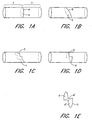
- Figures 1A-D therefore show various circumferential paths A , B , C , and D, respectively, each translating along a portion of a pulmonary vein wall and circumscribing a defined region of space, shown at a, b, c, and d also respectively, each circumscribed region of space being a portion of a pulmonary vein lumen.
- Figure 1E shows an exploded perspective view of circumferential path D as it circumscribes multiplanar portions of the pulmonary vein lumen shown at d', d", and d''', which together make up region d as shown in Figure 1D.
- transect including derivatives thereof, is also herein intended to mean to divide or separate a region of space into isolated regions.
- each of the regions circumscribed by the circumferential paths shown in Figures 1A-D transects the respective pulmonary vein, including its lumen and its wall, to the extent that the respective pulmonary vein is divided into a first longitudinal region located on one side of the transecting region, shown, for example, at region " X " in Figure 1A, and a second longitudinal region on the other side of the transecting plane, shown, for example, at region " Y " also in Figure 1A.
- a “circumferential conduction block” is formed along a region of tissue which follows a circumferential path, such as along the pulmonary vein wall and circumscribing the pulmonary vein lumen and transecting the pulmonary vein relative to electrical conduction along its longitudinal axis.
- the transecting circumferential conduction block therefore isolates electrical conduction between opposite longitudinal portions of the pulmonary wall relative to the conduction block and along the longitudinal axis.
- ablate or “ablation,” including derivatives thereof, are hereafter intended to mean the substantial altering of the mechanical, electrical, chemical, or other structural nature of tissue.
- ablation is intended to mean sufficient altering of tissue properties to substantially block conduction of electrical signals from or through the ablated cardiac tissue.
- ablation element within the context of "ablation element”, including derivatives thereof, is herein intended to mean a discrete element, such as an electrode, or a plurality of discrete elements, such as a plurality of spaced electrodes, which are positioned so as to collectively ablate a region of tissue.
- an "ablation element” may include a variety of specific structures adapted to ablate a defined region of tissue.
- one suitable ablation element for use in the present invention may be formed, according to the teachings of the embodiments below, from an "energy emitting” type which is adapted to emit energy sufficient to ablate tissue when coupled to and energized by an energy source.
- Suitable "energy emitting" ablation elements for use in the present invention may therefore include, for example: an electrode element adapted to couple to a direct current (“DC”) or alternating current (“AC”) current source, such as a radiofrequency (“RF”) current source; an antenna element which is energized by a microwave energy source; a heating element, such as a metallic element or other thermal conductor which is energized to emit heat such as by convective or conductive heat transfer, by resistive heating due to current flow, or by optical heating with light; a light emitting element, such as a fiber optic element which transmits light sufficient to ablate tissue when coupled to a light source; or an ultrasonic element such as an ultrasound crystal element which is adapted to emit ultrasonic sound waves sufficient to ablate tissue when coupled to a suitable excitation source.
- DC direct current
- AC alternating current source
- RF radiofrequency
- ablation elements other elements for altering the nature of tissue may be suitable as "ablation elements" under the present invention when adapted according to the detailed description of the invention below.
- a cryoablation element adapted to sufficiently cool tissue to substantially alter the structure thereof may be suitable if adapted according to the teachings of the current invention.
- a fluid ablation element such as a wall which is porous or has a discrete port (or a plurality of ports) which is fluidly coupied to a fluid delivery source, may be adapted to couple an ablation medium to the tissue for ablation.
- the fluid ablation element may infuse the ablation medium, such as a fluid containing alcohol, directly into the tissue adjacent to the wall in order to substantially alter the nature of that tissue.
- the fluid ablation element may supply radiofrequency or other mode of electrical current to the tissue by electrically coupling an electrical ablation element to the tissue via an ablation medium which is an electrically conductive fluid, such as for example an ionic fluid which may be, in one illustrative variation, hypertonic saline.
- ablation medium are intended to mean a medium that cooperates with one or more of the assemblies herein described in order to directly couple to and ablate the intended tissue.
- porous or “permeable”, including derivatives thereof, are herein used interchangeably and are intended to mean a material wall construction having sufficient void volume to allow a substance to permeate into and across the wall, including allowing for such substrate to elude through and out from the wall, such as by weeping or in fluid jets, or by merely “absorbing” the substrate into the void volume in the wall wherein substantial flow of the substrate completely through and from the wall is substantially limited or even prevented.
- porous or “permeable” materials for the purpose of illustration include without limitation: a material wall with inherent void volume upon formation of the wall; a material wall that is not inherently porous but with apertures formed therethrough such as for example by mechanical drilling or laserloptical drilling; and a material wall with chemically formed void volume.
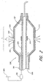
- the design includes a circumferential ablation member (200) with two insulators (202,204) that encapsulate the proximal and distal ends, respectively, of the working length L of an expandable member (210).
- the insulators (202,204) are distinct layers of material that cover a balloon skin (212) of balloon or expandable member (210).
- the expandable member (210) as shown in Figure 2 is joined at its proximal end to elongate body (201) that extends proximal to the expandable member (210). More particularly, Figure 2 shows the expandable member (210) and the elongate body (201) as being integrally formed, with the elongate body (201) extending from the expandable member (210) to the proximal end of the device outside of the patient (not shown).
- the distal end of the expandable member (210) is mounted to inner member (221) which extends through the elongate body (201) and expandable member (210) to the proximal end of the device.
- a lumen within the inner member (221) allows passage of a guidewire, as described in further detail below.
- the lumen defined between the elongate body (201) and the inner member (221) provides a passageway for fluids used in ablation and/or inflation of balloon (210). It will be appreciated that other designs may also be used for the circumferential ablation member. For instance, the expandable member (210) need not be integral with the elongate body (201), and may be separately mounted.
- this embodiment is not limited to a particular placement of the ablation element. Rather, a circumferential band may be formed anywhere along the working length of the expandable member and circumscribing the longitudinal axis of the expandable member as previously described.
- the balloon construction shown in Figure 2 forms an RF ablation electrode.
- An electrode (220) is provided on inner member (221) and is coupled to an ablation actuator shown at radiofrequency ("RF") current source (230) via electrical lead (225), thereby forming an internal current source within balloon (210).
- RF current source (230) is coupled to both the RF electrode element and also a ground patch (295) which is in skin contact with the patient to complete an RF ablation circuit.
- a porous membrane such as an expanded fluoropolymer, and more particularly an expanded polytetrafluoroethylene material, comprises the entire balloon skin (212) of expandable member (210).
- the porous skin (212) may be constructed according to several different methods, such as by forming holes in an otherwise contiguous polymeric material, including mechanically drilling or using laser energy, or the porous skin may simply be an inherently permeable material with inherent void volume forming pores for permeability, as will be developed according to more particular illustrative embodiments below.
- the porous skin By insulating the proximal and distal end portions of the working length of the expandable member as shown in Figure 2, only the pores along the circumferential band of the uninsulated intermediate region are allowed to ablatively couple the electrolyte which carries an ablative RF current into tissue. This uninsulated intermediate region thus forms a permeable section, while the insulated regions of the expandable member are non-permeable sections.
- the elongate body (201) is nonporous to prevent fluid from passing through the wall of the elongate body (201) before reaching the balloon chamber.
- the insulator (202) may extend over the elongate body (201) to insulate the elongate body (201). Further details regarding methods and apparatus for making a device permeable in certain portions and non-permeable in other portions are described below.
- an ablative fluid medium that is electrically conductive passes from a source (240) and into the internal chamber defined by the skin and outwardly into the porous wall of the balloon skin along the intermediate region until the solution directly couples to tissue.
- a source 240
- the porous region of the expandable member functions as an RF electrode wherein RF current flows outwardly into the tissue engaged by the balloon via the conductive fluid absorbed into the porous intermediate region of the wall.
- the ablation actuator mechanism for the overall assembly may also include or be coupled to a monitoring circuit (not shown) and/or a control circuit (not shown) which together use either the electrical parameters of the RF circuit or tissue parameters such as temperature in a feedback control loop to drive current through the electrode element during ablation. Also, where a plurality of ablation elements or electrodes in one ablation element are used, a switching means may be used to multiplex the RF current source between the various elements or electrodes.
- one further illustrative embodiment which is also contemplated provides an outer skin with the selectively porous intermediate region externally of another, separate expandable member, such as a separate expandable balloon, wherein the conductive fluid coupled to a current source is contained in a region between the outer skin and the expandable member contained therein.
- Figure 2 broadly illustrates an ablation balloon construction wherein an ablative surface is provided along the entire working length of an expandable member, but the surface is shielded or insulated from releasing ablative energy into surrounding tissues except for along an unshielded or uninsulated equatorial band.
- the insulator embodiment contemplates other ablation elements which are provided along the entire working length of an expandable member and which are insulated at their ends to selectively ablate tissue only about an uninsulated equatorial band.
- Other RF electrode arrangements are also considered suitable for use according to the selectively insulated ablation balloon embodiment shown in Figure 2.
- a metallized balloon includes a conductive balloon skin wherein the electrical insulators, such as polymeric coatings, are positioned over or under each end of the working length and thereby selectively ablate tissue with electricity flowing through the uninsulated equatorial band.
- the balloon skin may itself be metallized, such as by mixing conductive metal, including but not limited to gold, platinum, or silver, with a polymer to form a compounded, conductive matrix as the balloon skin.
- a discrete electrode element may be secured onto an outer surface of the balloon skin, such as in the embodiment when an expandable balloon is placed within an outer skin of selected porosity as just described above.
- porous aspects of the circumferential band are beneficially applied in a chemical ablation element mode, wherein a chemically ablative fluid medium such as an alcohol based medium is absorbed within the wall of the circumferential band and coupled to the tissue engaged to the band for ablation.
- a chemically ablative fluid medium such as an alcohol based medium
- the circumferential ablation member provided by the ablation balloon described may also include other ablative energy sources or sinks, and' particularly may include a thermal conductor that circumscribes the outer circumference of the working length of an expandable member.
- suitable thermal conductor arrangements include a metallic element which may, for example, be constructed as previously described for the more detailed RF embodiments above. However, in the thermal conductor embodiment such a metallic element would be generally either resistively heated in a closed loop circuit internal to the catheter, or conductively heated by a heat source coupled to the thermal conductor.
- the expandable member may be, for example, a polymeric balloon skin which is inflated with a fluid that is heated either by a resistive coil or by bipolar RF current.
- a thermal conductor on the outer surface of the expandable member is suitable when it is adapted to heat tissue adjacent thereto to a temperature between 40deg and 80deg Celsius.
- the insulators described may be only partial and still provide the relatively isolated ablative tissue coupling along the circumferential band.
- a partial electrical insulator will allow a substantial component of current to flow through the uninsulated portion due to a "shorting" response to the lower resistance in that region.
- balloon skin (212) may be thermally conductive to surrounding tissue when inflated with a heated fluid which may contain a radiopaque agent, saline fluid, ringers lactate, combinations thereof, or other known fluids having acceptable heat transfer properties for these purposes.
- Figure 2 further shows use of a electrode element (220) as a radiopaque marker to identify the location of the equatorial band (203) in order to facilitate placement of that band at a selected ablation region of a pulmonary vein via X-ray visualization.
- Electrode element (220) is opaque under X-ray, and may be constructed, for example, of a radiopaque metal such as gold, platinum, or tungsten, or may comprise a radiopaque polymer such as a metal loaded polymer.
- Figure 2 shows electrode element (220) positioned coaxially over an inner tubular member (221) which is included in a coaxial catheter design as would be apparent to one of ordinary skill.
- the present invention contemplates the combination of such a radiopaque marker additionally in the other embodiments herein shown and described.
- a radiopaque marker when the circumferential ablation member which forms an equatorial band includes a metallic electrode element, such electrode may itself be radiopaque and may not require use of a separate marker.
- various contemplated designs do not require positioning of the electrode (220) exactly along the band region, and therefore such electrode may be replaced with a simple radiopaque marker in order to retain the ability to locate the band within the body via X-ray visualization.
- the expandable member of the embodiments shown may take one of several different forms, although the expandable member is generally herein shown as an inflatable balloon that is coupled to an expansion actuator which is a pressurizeable fluid source.
- the expandable member forms a fluid chamber which communicates with a fluid passageway (not shown in all the figures) that extends proximally along the elongate catheter body and terminates proximally in a proximal fluid port that is adapted to couple to the pressurizeable fluid source.
- the embodiment of Figure 2 describes the expandable member (210) as being a balloon made of a porous fluoropolymer, such as an expanded polytetrafluoroethylene material It will be appreciated that various other materials may also be suitable for the balloon, or portions of the balloon, as described for the various embodiments herein. Several possible balloon materials are described below. These materials may have inherent porosity as would be known to one of skill in the art, or may be made porous according to several different methods, such as forming holes in an otherwise contiguous polymeric material.
- the balloon or portion thereof may be constructed of a relatively inelastic polymer such as a polyethylene (“PE”; preferably linear low density or high density or blends thereof), polyolefin copolymer (“POC”), polyethylene terepthalate (“PET”), polyimide, or a nylon material.
- PE polyethylene
- POC polyolefin copolymer
- PET polyethylene terepthalate
- the balloon has a low radial yield or compliance over a working range of pressures and may be folded into a predetermined configuration when deflated in order to facilitate introduction of the balloon into the desired ablation location via known percutaneous catheterization techniques.
- one balloon size may not suitably engage all pulmonary vein walls for performing the circumferential ablation methods of the present invention on all needy patients. Therefore, it is further contemplated that a kit of multiple ablation catheters, with each balloon working length having a unique predetermined expanded diameter, may be provided from which a treating physician may choose a particular device to meet a particular patient's
- the balloon may be constructed of a relatively compliant, elastomeric material, such as, for example (but not limited to), a silicone, latex, polyurethane, or mylar elastomer.
- a relatively compliant, elastomeric material such as, for example (but not limited to), a silicone, latex, polyurethane, or mylar elastomer.
- the balloon takes the form of a tubular member in the deflated, non-expanded state.
- fluid such as in the previous, relatively non-compliant example
- the material forming the wall of the tubular member elastically deforms and stretches radially to a predetermined diameter for a given inflation pressure.
- the compliant balloon may be constructed as a composite, such as, for example, a latex or silicone balloon skin which includes fibers, such as metal, Kevlar, or nylon fibers, which are embedded into the skin.
- fibers such as metal, Kevlar, or nylon fibers, which are embedded into the skin.
- Such fibers when provided in a predetermined pattern such as a mesh or braid, may provide a controlled compliance along a preferred axis, preferably limiting longitudinal compliance of the expandable member while allowing for radial compliance.
- the relatively compliant variation may provide a wide range of working diameters, which may allow for a wide variety of patients, or of vessels within a single patient, to be treated with just one or a few devices. Furthermore, this range of diameters is achievable over a relatively low range of pressures, which is believed to diminish a potentially traumatic vessel response that may otherwise be presented concomitant with higher pressure inflations, particularly when the inflated balloon is oversized to the vessel.
- the low-pressure inflation feature of this variation is suitable for the present invention because the functional requirement of the expandable balloon is merely to engage the ablation element against a circumferential path along the inner lining of the pulmonary vein wall.
- the balloon is preferably constructed to exhibit at least 300% expansion at 3 atmospheres of pressure, and more preferably to exhibit at least 400% expansion at that pressure.
- the term “expansion” is herein intended to mean the balloon outer diameter after pressurization divided by the balloon inner diameter before pressurization, wherein the balloon inner diameter before pressurization is taken after the balloon is substantially filled with fluid in a taught configuration.
- “expansion” is herein intended to relate to change in diameter that is attributable to the material compliance in a stress-strain relationship.
- the balloon is adapted to expand under a normal range of pressure such that its outer diameter may be adjusted from a radially collapsed position of about 5 millimeters to a radially expanded position of about 2.5 centimeters (or approximately 500% expansion ratio).
- a circumferential ablation member is adapted to conform to the geometry of the pulmonary vein ostium, at least in part by providing substantial compliance to the expandable member, as will be further developed below.
- the working length L of expandable member (1470) is also shown to include a taper which has a distally reducing outer diameter from a proximal end (1471) to a distal end (1473).
- a distally reducing tapered geometry adapts the circumferential ablation element to conform to the funneling geometry of the pulmonary veins in the region of their ostia in order to facilitate the formation of a circumferential conduction block there.
- expandable members than a balloon may also be suitable according to the insulator aspects of the invention.
- various modes of known expandable cages may be sufficient expandable members for this invention so long as a fluid chamber is at least in part enclosed by or otherwise associated with the cage so as to provide for ablative fluid coupling to tissue as broadly contemplated by the disclosed embodiments.
- the circumferential band (203) shown in Figure 2 and elsewhere throughout the figures generally has a functional band width w relative to the longitudinal axis of the working length which is only required to be sufficiently wide to form a complete conduction block against conduction along the walls of the pulmonary vein in directions parallel to the longitudinal axis.
- the working length L of the respective expandable element is adapted to securely anchor the distal end portion in place such that the ablation element is firmly positioned at a selected region of the pulmonary vein for ablation.
- the band width w is relatively narrow compared to the working length L of the expandable element, and the electrode band may thus form a relatively narrow equatorial band which has a band width that is less than two-thirds or even one-half of the working length of the expandable element.
- a narrow band may be placed at locations other than the equator of the expandable element, preferably as long as the band is bordered on both sides by a portion of the working length L .
- the circumferential lesion formed may also be relatively narrow when compared to its own circumference, and may be less than two-thirds or even one-half its own circumference on the expandable element when expanded.
- the band width w is less than 1 cm with a circumference on the working length when expanded that is greater than 1.5 cm.
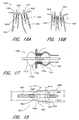
- energy is coupled to the tissue largely via the ablative medium supplied by the inflation fluid and porous or permeable balloon skin. It is believed that, for in vivo uses of the present invention, the efficiency of energy coupling to the tissue, and therefore ablation efficiency, may significantly diminish in circumstances where there is poor contact and conforming interface between the balloon skin and the tissue. Accordingly, several different balloon types may be provided for ablating different tissue structures so that a particular shape may be chosen for a particular region of tissue to be ablated, such as for example in order to accommodate differing geometries encountered when ablating circumferential regions of tissue to isolate various different pulmonary veins in either the same of different patients, as further developed elsewhere hereunder, and by reference to Figures 17 21 below.
- the elongate body (201) of the overall catheter assembly shown in Figure 2, and as appropriate elsewhere throughout this disclosure, may have an outer diameter provided within the range of from about 15 mm (5 French) to about 30mm (10 French) and more preferable from about 21mm (7 French) to about 27mm (9 French).
- the guidewire lumen preferably is adapted to slideably receive guidewires ranging from about 0.025cm (0.010 inch to about 0.097cm (0.038 inch) in diameter, and preferably is adapted for use with guidewires ranging from about 0.018 inch to about 0.098cm (0.035 inch)in diameter.
- the guidewire lumen preferably has an inner diameter of 0,10cm (0.040 inch) to about 0,107 cm (0.042 inch).
- the inflation lumen preferably has an inner diameter of about 0.020 inch in order to allow for rapid deflation times, although the diameter may vary based upon the viscosity of inflation medium used, length of the lumen, and other dynamic factors relating to fluid flow and pressure.
- the elongate body (201) should also be adapted to be introduced into the left atrium such that the distal end portion with balloon and transducer may be placed within the pulmonary vein ostium in a percutaneous transiumenal procedure, and even more preferably in a transeptal procedure as otherwise herein provided. Therefore, the distal end portion of the body (201) is preferably flexible and adapted to track over and along a guidewire seated within the targeted pulmonary vein. In one further more detailed construction which is believed to be suitable, the proximal end portion is adapted to be at least 30% stiffer than the distal end portion.
- the proximal end portion may be suitably adapted to provide push transmission to the distal end portion while the distal end portion is suitably adapted to track through bending anatomy during in vivo delivery of the distal end portion of the device into the desired ablation region.
- FIG. 2 shows an "over-the-wire" catheter construction
- other guidewire tracking designs may be suitable substitutes, such as, for example, catheter devices which are known as “rapid exchange” or “monorail” variations wherein the guidewire is only housed coaxially within a lumen of the catheter in the distal regions of the catheter.
- a deflectable tip design may also be a suitable substitute and which is adapted to independently select a desired pulmonary vein and direct the transducer assembly into the desired location for ablation.
- the guidewire lumen and guidewire of the Figure 2 variation may be replaced with a "pullwire" lumen and associated fixed pullwire which is adapted to deflect the catheter tip by applying tension along varied stiffness transitions along the catheter's length.
- acceptable pullwires may have a diameter within the range from about 0,02 cm (0.008 inch) to about 0,051 cm (0.020 inch), and may further include a taper, such as, for example, a tapered outer diameter from about 0,051 cm (0.020 inch) to about 0,020 cm (0.008 inch).
- FIGS 3A-B illustrate such an additional variation of the tissue ablation device assembly (300) wherein an ablation balloon (310) is beneficially secured over a steerable delivery member (302) which may be similar for example to deflectable tip electrode catheter and/or according to various steerable cardiac electrophysiology mapping catheters, such as those known in the art.
- Outer member (301) is shown coaxially disposed over steerable delivery member (302) such that permeable band (303) of balloon (310) provided by outer sheath (301) is disposed around electrode (320) provided on the steerable delivery member (302).
- Inflation device (340) is fluidly coupled with the inner fluid chamber formed by balloon (310) and includes a pressurized source of an ablative medium such as electrically conductive fluid.
- An ablation actuator which in the Figure 3A embodiment is RF current source (330) is coupled with electrode (320). Furthermore, tip electrode mapping/actuator assembly (314) is also shown coupled with tip electrode (310) via tip electrode lead (313). Further to the particular variation shown in Figures 3A-B, the distal end of pullwire (311) is schematically shown to be secured to the distal end of the steerable delivery member (301), whereas the proximal end of pullwire (311) is shown coupled to deflection actuator (314) which is adapted to controllably provide forces on pullwire (311) such that the distal end of assembly (300) is deflected or shaped as desired for torsional steering.
- Balloon (310) is secured to the outer surface (321) of steerable delivery member (302) via bond (305) such that a fluid tight seal is provided and further such that balloon (310) and steerable delivery member (302) are in a fixed relationship to each other such that they may be manipulated and controllably positioned together via transcatheter techniques.
- assembly (300) is shown delivered into a left atrium through a transeptal sheath (350), wherein it is shaped (illustrated by double headed arrows in Figure 3B) and positioned within a pulmonary vein. More specifically, band (303) is engaged to circumferential region of tissue (370) in order to ablatively couple electrode (320) through band (303) and to tissue (370) via the ablative fluid medium absorbed into the wall of band (303).
- the electrode (320) need not be positioned exactly along band (303) relative to the long axis of device assembly (300) in order to electrically couple the electrode to fluid and thereby to the band and tissue surrounding the band.
- electrode (320) is preferably a radiopaque material such as a metal, and considering an increase in impedance when moving electrode (320) further away from band (303), the embodiment shown is believed to be highly beneficial. If another electrical source were provided such that there were no electrode (320) within balloon (310), then a separate radiopaque band may be provided at a similar location where electrode (320) is shown in Figure 3A in order to provide a marker to position band (303) where desired, such as along circumferential region of tissue (370) as shown in Figure 3B.
- the Figure 4A.C embodiment provides a steerable electrode catheter/balloon assembly (400) that differs from the Figure 3A.C embodiment in that the steerable delivery member (402) in Figures 4A.C is moveably engaged within an interior passageway of a separate outer member (401) that provides balloon (410) in a separate sheath assembly that surrounds steerable delivery member (402).
- Section A in Figure 4A indicates the portion of the outer member (401) that does not expand when filled with fluid, while Section B in Figure 4B defines the balloon portion that does expand when filled with fluid.
- outer member (401) is characterized as being: (a) closed at the distal end; and (b) inflatable along balloon (410) if pressurized with fluid from pressurizeable fluid source (440) containing electrically conductive fluid.
- electrode (420) is aligned with band (403) such that expansion of balloon (410) and actuation of electrode (420) ablates a circumferential band of tissue (470) engaged to band (403), as shown in Figure 4B.
- the steerable delivery member (402) is preferably of the deflectable variety known in the art, and therefore allows for controllable positioning of the balloon (410) before, during, or after expansion and circumferential ablation, wherein such deflection is shown for the purpose of illustration in Figure 4C.
- this Figure 4A-C embodiment allows for the outer member (401) to be selectively fit over and used with any commercially available steerable catheters, such as for example commercially available, "deflectable tip" RF ablation catheters.
- indicia may be provided on either or both of outer and inner catheters of this assembly, such as either visible markings on portions of the associated members extending externally of the body, or radiopaque markers that allow x-ray guided alignment of the assemblies.
- Figures 5A-E show various modes for making a porous band along a working length of a circumferential ablation balloon. More specifically, Figures 5A-5E show methods for post-processing a pre-formed balloon that is either totally porous (Figure 5A) or totally non-porous (Figure 5B), respectively, prior to post-processing. More specifically, Figure 5C shows a method wherein the totally porous balloon of Figure 5A is exposed to a filling agent, such as in a dip-coating or other deposition method.
- a filling agent such as in a dip-coating or other deposition method.
- Figure 5C illustrates the method for treating the totally porous starting balloon of Figure 5A.
- Intermediate region (503) is masked off and insulated from being filled during the deposition procedure, and thereafter is left porous when the insulator is removed after filling, leaving only the uninsulated ends non-porous due to the filler (505) introduced into the pores there.
- Figure 50 illustrates the method using a totally non-porous balloon material from Figure 5B and masks end portions (502) and (504) while intermediate region or band (503) is left uninsulated and exposed.
- the bath shown in shadow in Figure 50 contains not filler for filling the pores along the balloon as was just illustrated for Figure 5C, but instead contains a solvent (506) that removes material where exposed to the balloon, for example from filled pores to be cleansed and opened for fluid flow.
- the method just described for selectively masking the intermediate region and then exposing the entire balloon to filler may be modified. Without masking the porous balloon, the two end portions of the balloon may be dipped into a filler, such that the intermediate region is "undipped" or left out of the dipping material and the only region left porous according to the invention.
- Figure 6A allows for the formation of the discrete intermediate permeable band (603) when a base product or tube (600) of a non-expanded, relatively non-permeable fluoropolymer or similar material is used.
- Figure 6B shows tube (600) being stretched (see illustrative arrows) while only intermediate region (603) is being heated, at the exclusion of end portions (602) and (604) in order to isolate deformation along that intermediate region (603).
- Such deformation is known to "expand" the substrate fluoropolymer such that the node and fibril network is stretched with larger void volumes than in the relatively "un expanded” end portions.
- intermediate region (603) is left as a circumferential, permeable band of expanded fluoropolymer.
- the end portions of such selectively expanded tube may be incorporated onto a delivery and ablation source assembly such as according to the embodiments elsewhere herein described, such as by forming the tube into a balloon (610) as shown in Figure 60 and then adapting it to the distal end of an over-the-wire ablation catheter assembly or deflectable tip inner electrode catheter.
- a balloon may beneficially be folded for in vivo delivery to the left atrium and pulmonary vein. Examples of such folds are variously shown throughout Figures 7A-D.
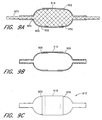
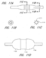
- Fluid permeable fluoropolymer such as polytetrafluoroethylene may also be provided only along the intermediate region, wherein the end portions of the working length of the ablation balloon are formed from another material grafted or otherwise secured to the permeable intermediate material, as variously shown by example and without limitation in Figures SA-10E.
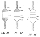
- Figures 8A-C show a method for constructing such a balloon with varied material composition over the working length.
- Figure 8A shows a mandrel (800) with an enlarged region (802) sized to support permeable tubing (810) which may be for example a fluoropolymer such as an expanded PTFE material.
- An elastic member (820) is advanced over one narrow end of mandrel (800) until it elastically is forced open as it is advanced over the enlarged region (802) and further over permeable tubing (810) to create an overlap zone (825), as shown in Figure 8B.
- the same is done on the opposite side, as shown in Figure 8C, to produce the final grafted balloon which may be then removed from the mandrel.
- the elastomeric end portions may be bonded to the permeable membrane along the intermediate region according to a variety of methods.
- the end portions are thermoplastic polymers which may be melted and then flow into the pores of the permeable membrane.
- a separate bonding agent such as a solvent bonding agent or an adhesive may also be used to accomplish the bonding along the overlap region, as is shown by use of bonding agent (1012) by reference to Figures 10A-D in a similar method to that shown in Figures 8A-C.
- Figure 10E shows balloon (1000) being removed from the mandrel after formation according to the method illustrated in Figures 10A-D, and further illustrates the novel result of the present method which provides a balloon having elastomeric end portions with a relatively non-elastomeric intermediate region (1010).
- This relationship is further illustrated in various views of balloon (1000) in Figures 11A-D, showing one mode for folding the relatively non-elastomeric intermediate region (1010) while the balloon is in a deflated or radially collapsed condition in Figures 11A-C, and another mode for the assembly in the inflated or radially expanded condition in Figure 110.
- FIGS 12A-D show various modes of porous fluoropolymer, or more specifically polytetrafluoroethylene (PTFE), which is believed to be a highly beneficial material for use in the assemblies and methods according to the present invention, and in particular the porous circumferential band embodiments.
- expanded PTFE as shown at porous material (1200) generally includes a plurality of nodes (1202) and interconnecting fibrils (1204) which form a network.
- voids (1206) which provide the porosity or permeability desired for a particular application of the ablation assemblies and methods of the present invention.
- the specific material used for the application may be selected from a variety of commercially available materials having different pore sizes.
- the voids (1206) may also be filled with a filler (1208) such that permeability is attenuated or completely blocked.
- U.S. Patent No. 5,753,358 to Korleski, and U.S. Patent No. 5,766,750 to Korleski disclose an adhesive composite material comprising an expanded fluoropolymer with nodes and interconnected fibrils, the fluoropolymer having a void volume which is at least partially filled by any of a number of fillers. Any of the biocompatible and nontoxic fillers disclosed in these patents may be appropriate for use in accordance with the embodiments of the present invention. Such a construction may be appropriate for the methods of manufacturing an ablation balloon as shown and described above by reference to Figures 5A-E.
- a starting material according to Figure 12A may be provided for the method illustrated by reference to Figures 5A and C, wherein intermediate region (503) is masked while filler (1208) fills all the void volumes along end portions (502,504).
- the result is a construction along intermediate region (503) that is consistent with Figure 12A, but a construction along end portions (502,504) that is consistent with Figure 12B.
- the whole balloon may be filled in a construction consistent with Figure 12B and then the filler selectively moved from only the intermediate portion (503), yielding a similar.result just described.
- FIG. 12C A comparison of Figures 12C and D also further illustrates a selective porosity embodiment along a contiguous fluoropolymeric balloon construction (fluoropolymer integral along whole working length of balloon), such as according to the method shown and described by reference to Figures 6A-D. More specifically considering the structure shown in Figure 12D by reference to Figures 6A.D, end portions (602,604) shown in Figures 6C or D may have a material construction consistent with for example the denser, less expanded region of compacted nodes (1202) designated by their distance D1 in Figure 12D. The porous region (603) however would be representative of the more expanded region designated by the inter-nodule distance 02 in Figure 12D. Thus, by providing varying regions of density and material "expansion" along the balloon working length, the selected intermediate region of permeability for ablation may be achieved.
- Figures 13A-15C show sequential modes for using a circumferential ablation catheter assembly in treating atrial fibrillation.
- an "over-the-wire" delivery mode is herein shown and described, it is further contemplated that other delivery modes such as the deflectable steerable modes described above referring to Figures 3A-4C.
- a patient diagnosed with atrial arrhythmia is treated according to one embodiment of the present invention by forming a circumferential conduction block using the device assemblies herein described.
- the term "diagnose”, including derivatives thereof, is intended to include patients suspected or predicted to have atrial arrhythmia, in addition to those having specific symptoms or mapped electrical conduction indicative of atrial arrhythmia.
- a patient diagnosed with multiple wavelet arrhythmia originating from multiple regions along the atrial wall may also be treated in part by forming the circumferential conduction block, although as an adjunct to forming long linear regions of conduction block between adjacent pulmonary vein ostia in a less-invasive "maze"-type catheter ablation procedure.
- a patient diagnosed with focal arrhythmia originating from an arrhythmogenic origin or focus in a pulmonary vein is treated according to this method when the circumferential conduction block is formed along a circumferential path of tissue that either includes the arrhythmogenic origin or is between the origin and the left atrium.
- the arrhythmogenic tissue at the origin is destroyed by the conduction block as it is formed through that focus.
- the arrhythmogenic focus may still conduct abnormally, although such aberrant conduction is prevented from entering and affecting the atrial wall tissue due to the intervening circumferential conduction block.
- the sequential steps of a method for using the circumferential ablation device assembly according to one embodiment of the present invention in forming a circumferential conduction block at a location where a pulmonary vein extends from a posterior left atrial wall include: positioning a circumferential ablation element at an ablation region along the location; and thereafter ablating a continuous circumferential region of tissue along the location.
- a distal tip of a guiding catheter is first positioned within the left atrium according to a transeptal access method, which is further described in more detail as follows.
- the right venous system is first accessed using the "Seldinger" technique, wherein a peripheral vein (such as a femoral vein) is punctured with a needle, the puncture wound is dilated with a dilator to a size sufficient to accommodate an introducer sheath, and an introducer sheath with at least one hemostatic valve is seated within the dilated puncture wound while maintaining relative hemostasis.
- the guiding catheter or sheath is introduced through the hemostatic valve of the introducer sheath and is advanced along the peripheral vein, into the region of the vena cavae, and into the right atrium.
- the distal tip of the guiding catheter is positioned against the fossa ovalis in the intraatriai septal wall.
- A. "Brockenbrough" needle or trocar is then advanced distally through the guide catheter until it punctures the fossa ovalis.
- a separate dilator may also be advanced with the needle through the fossa ovalis to prepare an access port through the septum for seating the guiding catheter.
- the guiding catheter thereafter replaces the needle across the septum and is seated in the left atrium through the fossa ovalis, thereby providing access for object devices through its own inner lumen and into the left atrium.
- left atrial access methods may be suitable substitutes for using the circumferential ablation device assembly of the present invention.
- a "retrograde" approach may be used, wherein the guiding catheter is advanced into the left atrium from the arterial system.
- the Seldinger technique is employed to gain vascular access into the arterial system, rather than the venous, for example, at a femoral artery.
- the guiding catheter is advanced retrogradedly through the aorta, around the aortic arch, into the ventricle, and then into the left atrium through the mitral valve.
- a guidewire is then advanced into a pulmonary vein, which is done generally through the guiding catheter seated in the fossa ovalis.
- the guidewire according to this variation may also be advanced into the pulmonary vein by directing it into the vein with a second sub-selective delivery catheter (not shown) which is coaxial within the guiding catheter, such as, for example, by using one of the directional catheters disclosed in US Patent No. 5,575,766 to Swartz, the entirety of which is hereby incorporated by reference.
- the guidewire may have sufficient stiffness and maneuverability in the left atrial cavity to unitarily subselect the desired pulmonary vein distally of the guiding catheter seated at the fossa ovalis.
- Suitable guidewire designs for use in the overall circumferential ablation device assembly of the present invention may be selected from previously known designs, while generally any suitable choice should include a shaped, radiopaque distal end portion with a relatively stiff, torquable proximal portion adapted to steer the shaped tip under X-ray visualization.
- Guidewires having an outer diameter ranging from 0,025 cm (.010”) to 0,089 cm (.035") may be suitable.
- guidewires having an outer diameter ranging from 0,046 cm (.018”) to 0,089 cm (.035") may be required.
- guidewires within this size range may be required to provide sufficient stiffness and maneuverability in order to allow for guidewire control and to prevent undesirable guidewire prolapsing within the relatively open atrial cavity.
- the distal end portion of a circumferential ablation device assembly is then tracked over the guidewire and into the pulmonary vein, followed by positioning a circumferential ablation element at an ablation region of the pulmonary vein where the circumferential conduction block is to be desirably formed.
- FIG. 13A shows a circumferential ablation device system (1300) according to one embodiment of the present invention during use as just described, which circumferential ablation system (1300) includes a guiding catheter (1301), guidewire (1302), and circumferential ablation catheter (1303).
- Figure 13A shows guiding catheter (1301) subsequent to performing a transeptal access, and also shows guidewire (1302) subsequent to advancement and positioning within a pulmonary vein.
- Figure 13A shows circumferential ablation catheter (1303) as it tracks coaxially over guidewire (1302) with a distal guidewire tracking member, which is specifically shown only in part at first and second distal guidewire ports (1342,1344) located on the distal end portion (1332) of an elongate catheter body (1330).
- a guidewire lumen extends between the first and second distal guidewire ports (1342, 1344) and is adapted to slideably receive and track over the guidewire.
- the second distal guidewire port (1342) is located on a distal end portion (1332) of the elongate catheter body (1330), although proximally of first distal guidewire port (1342).
- the distal guidewire tracking member configuration shown in Figure 13A and just described has the following attributes normally associated with "rapid exchange” or “monorail” catheters according to persons of ordinary skill.
- such assembly may be easily slideably coupled to the guidewire externally of the body in a "backloading" technique after the guidewire is first positioned in the pulmonary vein and without the need for extra long wires.
- this guidewire tracking variation removes the need for a guidewire lumen in the proximal portions of the elongate catheter body (1330), which allows for a reduction in the outer diameter of the catheter shaft in that region.
- a catheter according to the invention may instead incorporate a design which places the second distal guidewire port on the proximal end portion of the elongate catheter body, as would be normally associated with "over-the-wire" catheters according to one of ordinary skill.
- guidewire tracking members which form a bore adapted to slideably receive and track over a guidewire are also considered acceptable, such as, for example, the structure adapted to engage a guidewire as described in U.S. Patent No. 5,505,702 to Arney.
- an alternative circumferential ablation catheter not shown may include a "fixed-wire"-type of design wherein a guidewire is integrated into the ablation catheter as one unit.
- the same type of sub-selective sheaths described above with reference to U.S. Patent No. 5,575,766 to Swartz for advancing a guidewire into a pulmonary vein may also be used for advancing a circumferential ablation catheter device across the atrium and into a pulmonary vein.
- Figure 13A also shows circumferential ablation catheter (1303) with a circumferential ablation element (1360) formed on an expandable member (1370).
- the expandable member (1370) is shown in Figure 13A in a radially collapsed position adapted for percutaneous translumenal delivery into the pulmonary vein.
- expandable member (1370) is also adjustable to a radially expanded position when actuated by an expansion actuator (1375), as shown in Figure 13B.
- Expansion actuator (1375) may include, but is not limited to, a pressurizeable fluid source.
- expandable member (1370) includes a working length L relative to the longitudinal axis of the elongate catheter body which has a larger expanded outer diameter OD than when in the radially collapsed position. Furthermore, the expanded outer diameter OD is sufficient to circumferentially engage the ablation region of the pulmonary vein.
- working length are herein intended to mean the length of an expandable member which, when in a radially expanded position, has an expanded outer diameter that is: (a) greater than the outer diameter of the expandable member when in a radially collapsed position; and (b) sufficient to engage a body space wall or adjacent ablation region surrounding the expandable member, at least on two opposing internal sides of the body space wall or adjacent ablation region, with sufficient surface area to anchor the expandable member.
- Circumferential ablation element (1360) also includes a circumferential band (1352) on the outer surface of working length L which is coupled to an ablation actuator (1390) at a proximal end portion of the elongate catheter body (shown schematically).
- the circumferential band (1352) of the circumferential ablation element (1360) is actuated by ablation actuator (1390) to ablate the surrounding circumferential path of tissue in the pulmonary vein wall, thereby forming a circumferential lesion that circumscribes the pulmonary vein lumen and transects the electrical conductivity of the pulmonary vein to block conduction in a direction along its longitudinal axis.
- RF energy is delivered to the circumferential region of tissue in part by delivering RF energy from the ablation actuator to electrodes via electrical leads.
- electrically conductive fluid such as saline, is directed into the fluid chamber formed by balloon and is absorbed into the void volume of permeable circumferential band, whereby electrical current may flow from the electrode, through the fluid, across the wall of balloon, and into the circumferential region of tissue.
- a pertusion lumen may be formed within the distal end portion (1332) of elongate catheter body (1330).
- the perfusion lumen may for example be formed between a distal perfusion port, such as at distal guidewire port (1342), and a proximal perfusion port (1344) which may be formed through the wall of the elongate catheter body (1330) and communicate with the guidewire lumen (not shown) which also forms the perfusion lumen between the distal and proximal pertusion ports.
- the guidewire is withdrawn proximally of the proximal perfusion port (1344) (shown schematically in shadow) so that the lumen between the ports is clear for antegrade blood flow into the distal perfusion port (1342), proximally along the perfusion lumen, out the proximal perfusion port (1344) and into the atrium (perfusion flow shown schematically with arrows).
- Figure 13C shows the pulmonary vein (1351) after removing the circumferential ablation device assembly subsequent to forming a circumferential lesion (1372) around the ablation region of the pulmonary vein wall (1353) according to the use of the circumferential ablation device assembly shown in stepwise fashion in Figures 13A-B.
- Circumferential lesion (1370) is shown located along the pulmonary vein adjacent to the pulmonary vein ostium (1354), and is shown to also be "transmural,” which is herein intended to mean extending completely through the wall, from one side to the other.
- circumferential lesion (1370) is shown in Figure 13C to form a "continuous" circumferential band, which is herein intended to mean without gaps around the pulmonary vein wall circumference, thereby circumscribing the pulmonary vein lumen.
- Various other references to similar anatomical locations or structures are elsewhere made throughout this disclosure with similar reference numerals attached to the end of the respective figure number (e.g., expandable member 1370 in Figure 13A is referred to as expandable member 1470 in Figure 14A).
- circumferential catheter ablation with a circumferential ablation element according to the present invention may leave some tissue, either transmurally or along the circumference of the lesion, which is not actually ablated, but which is not substantial enough to allow for the passage of conductive signals. Therefore, the terms "transmural” and “continuous” as just defined are intended to have functional limitations, wherein some tissue in the ablation region may be unablated but there are no functional gaps which allow for symptomatically arrhythmogenic signals to conduct through the conduction block and into the atrium from the pulmonary vein.
- Figures 14A-B show a further variation in another embodiment of the present invention, wherein a circumferential ablation member (1450) includes a radially compliant expandable member (1470) which is adapted to conform to a pulmonary vein ostium (1454) at least in part by adjusting it to a radially expanded position while in the lett atrium and then advancing it into the ostium.
- Figure 14A shows expandable member (1470) after being adjusted to a radially expanded position while located in the left atrium (1450).
- Figure 14B further shows expandable member (1470) after being advanced into the pulmonary vein (1451) until at least a portion of the expanded working length L of circumferential ablation member (1450), which includes a circumferential band (1452), engages the pulmonary vein ostium (1454).
- Figure 14C shows a portion of a circumferential lesion (1472) which forms a circumferential conduction block in the region of the pulmonary vein ostium (1454) subsequent to actuating the circumferential ablation element to form the circumferential lesion.
- expandable member (1470) is also shown in Figure 14B to engage a circumferential path of tissue along the left posterior atrial wall which surrounds ostium (1454).
- circumferential band (1452) of the circumferential ablation member is also thereby adapted to engage that atrial wall tissue. Therefore, the circumferential conduction block formed according to the method shown and just described in sequential steps by reference to Figures 14A-B, as shown in-part in Figure 14C, includes ablating the circumferential path of atrial wall tissue which surrounds ostium (1454).
- the entire pulmonary vein, including the ostium is thereby electrically isolated from at least a substantial portion of the left atrial wall which includes the other of the pulmonary vein ostia, as would be apparent to one of ordinary skill according to the sequential method steps shown in Figures 14A-B and by further reference to the resulting circumferential lesion (1472) shown in Figure 14C.
- the lesion shown in Figure 14C isolates the pulmonary vein, but is formed by ablating tissue surrounding the pulmonary vein, although while also within the pulmonary vein. It is further contemplated that such lesion may be formed only along the posterior left atrial wall and surrounding the pulmonary vein ostium, without also ablating tissue along the lumen or lining of the pulmonary vein or ostium, depending upon the particular shape of the balloon and/or position and geometry of the ablative band along that balloon.
- the compliant nature of the expandable member may be self-conforming to the region of the ostium such that the circumferential band is placed against this atrial wall tissue merely by way of conformability.
- a pear-shaped balloon with a distally reducing outer diameter may provide a "forward-looking" face which, with the ablative band provided along that forward-looking face, is adapted to advance against such atrial wall tissue and ablate there.
- a pear shape may be preformed into the expandable member or balloon, or the member may be adapted to form this shape by way of controlled compliance as it expands, such as for example by the use of composite structures within the balloon construction.
- the circumferential band of the ablation member is preferably placed along the surface of the contoured taper which is adapted to face the left posterior atrial wall during use, such as for example according to the method illustrated by Figures 14A-B.
- Figures 15A-C show such a pear-shaped ablation balloon in a circumferential ablation member assembly adapted to electrically isolate a pulmonary vein and ostium from a substantial portion of the left posterior atrial wall, which embodiment isolates the pulmonary vein without also ablating tissue along the lumen or lining of the pulmonary vein or ostium.
- Figure 15A shows circumferential band (1552') to have a geometry (primarily width) and position along expandable member (1570') such that it is adapted to engage only a circumferential path of tissue along the left posterior atrial wall which surrounds the pulmonary vein ostium.
- the compliant nature of the expandable member may be self-conforming to the region of the ostium such that the circumferential band is placed against this atrial wall tissue merely by way of conformability.
- a "pear"-shaped expandable member or balloon that includes a contoured taper may be suitable for use according to the Figure 15A embodiment, as is shown by way of example in Figure 15B.
- a pear shape may be preformed into the expandable member or balloon, or the member may be adapted to form this shape by way of controlled compliance as it expands, such as for example by the use of composite structures within the balloon construction.
- the circumferential band (1552') of the ablation member is preferably placed along the surface of the contoured taper which is adapted to face the left posterior atrial wall during use according to the method illustrated by Figure 15A.
- the ablation element may be further extended or alternatively positioned along other portions of the taper, such as is shown by example in shadow at extended band (1552") in Figure 15B. Accordingly, the variation shown in Figure 15B to include extended band (1552") may also adapt this particular device embodiment for use in forming circumferential conduction blocks also along tissue within the pulmonary vein and ostium, such as according to the previously described method shown in Figures 15A-C.
- tissue ablation device systems shown and described below by reference to Figures 16A-21 are also believed to be beneficial for ablating tissue at certain locations where one or more pulmonary veins extend from an atrium.
- the tissue ablation device system (1600) shown in Figures 16A-B includes two circumferential ablation devices (1630,1640) in two pulmonary vein branches (1610,1620) which form adjacent ostia along an atrial wall.
- Each of devices (1630,1640) has a circumferential ablation member (1632,1642), respectively, which is shown to include an expandable member (1635,1645), also respectively, and an ablative energy source (1637,1647), also respectively.
- Each respective ablative energy source (1637,1647) is adapted to ablatively couple to a circumferential region of tissue at the base of the respective pulmonary vein (1610,1620), and if properly positioned, may combine to ablate tissue between the adjacent veins (1610,1620), as shown specifically in Figure 16B wherein the expandable members expand the veins (1610,1620) to bring them together to assist the combined ablative coupling from each device to the tissue therebetween.
- Pulmonary veins have also been observed to present a thickened cuff of tissue at their respective ostia, which thickened cuff is believed to present a unique resistance to expansion of an expandable member with a working length extending from the atrium, across the ostia, and into the more compliant vein adjacent the ostium. Therefore, one embodiment of the invention further contemplates an expandable balloon having a shape with a waist which assists the balloon to seat at the thickened, less compliant ostium and position the ablative circumferential band of the ablation assembly there.
- FIG. 17 Such an embodiment is shown in Figure 17, wherein device (1700) is shown with a circumferential ablation member (1710) having an expandable member (1720) that is a balloon with a narrowed waist (1723) between two larger end portions (1720,1724) of the working length. As shown, distal end portion (1724) of the balloon's working length expands with the vein wall, and proximal end portion (1720) of the balloon's working length expands to a relatively large outer diameter as the ostium becomes atrium.
- a circumferential ablation member (1710) having an expandable member (1720) that is a balloon with a narrowed waist (1723) between two larger end portions (1720,1724) of the working length.
- distal end portion (1724) of the balloon's working length expands with the vein wall
- proximal end portion (1720) of the balloon's working length expands to a relatively large outer diameter as the ostium becomes atrium.
- waist (1723) with its reduced diameter allows the assembly to seat at the thicker ostium with ablation element (1730) well positioned to ablatively couple through expandable member (1720) and into the circumferential region of tissue along the ostium, such as for example according to the balloon embodiments with a permeable circumferential band as described above.
- a balloon such as just described for Figure 17, in addition to particular ablation element/expandable member configurations, and still benefit by the "peanut" or waisted balloon shape with regards to pulmonary vein ostium ablation.
- material construction either a substantially compliant or elastomeric balloon material, or a substantially non-compliant or non-elastomeric variety may be used.
- a combination balloon construction with elastomeric/compliant and non-elastomeric/non-compliant regions along the working length, such as herein described, may be suitable.
- Figure 18 shows a further iteration of a "waisted" balloon shape for circumferential ablation member (1810), and in particular shows distal shoulder (1824) of expandable member or balloon (1820) having a steeper angled taper (1824') onto the distal adaption to the underlying catheter body (1801) than is shown for taper (1822') between catheter body (1801) and proximal shoulder (1822).
- the dimensions at the distal most portion of the assembly may be desirably as blunt as possible, whereas certain pulmonary veins have been observed to quickly branch or otherwise narrow in close proximity to the ostium and thereby prevent the distal end of the ablation device to be advanced very far through the respective os for ablation.
- the steeper distal taper (1824') allows the waist region (1823), including in various particular embodiments the ablative circumferential band coupled to the ablation element (1837), to be placed as distally as possible on the underlying catheter body (1801) to ensure the ability to ablate the os.
- Figures 19A-21 show various uses of multiple expansion elements in order to assist in the proper positioning of the ablation element and respective expandable member for ablative coupling to a circumferential region of tissue where a pulmonary vein extends from an atrium.
- Figure 19A shows a circumferential ablation member (1900) with an expandable member (1910) and an ablation element (1940).
- Expandable member (1910) includes an outer tubular wall (1912) which surrounds each of two spaced inner expansion elements (1920,1930). According to this configuration, inner expansion elements (1920,1930) are located along first and second end portions a,c of the working length L of expandable member (1910).
- the proximal inner expansion element (1920) is shown in Figure 19A as a balloon which is fluidly coupled to a source of inflation fluid via port (1922), whereas distal inner expansion element (1930) is also shown as a balloon and is fluidly coupled to a source of inflation fluid via port (1932).
- Proximal inner expansion element (1920) is adapted to expand to a larger outer diameter D than the outer diameter d for distal expansion element (1930), and thereby the overall expandable member (1910) results in an overall tapered shape and in particular imparting a taper with a distally reducing outer diameter along tubular wall (1912) extending between the different diameter expansion elements (1920,1930).
- the spacing between expansion elements (1920,1930) defines an intermediate region b wherein an interior chamber (1915) is enclosed by outer tube (1912) extending between the expansion elements (1920,1930).
- Interior chamber (1915) is adapted to be fluidly coupled to a source of ablative medium (not shown) via port (1917) into a fluid passageway (also not shown) extending along elongate body (1901).
- An ablation element (1940) is provided on elongate body (1901) between expansion elements (1920,1930) and within interior chamber (1915), and is adapted to be coupled to an ablation actuator along a proximal end portion (not shown) of body (1901).
- both proximai and distal inner expansion elements (1920,1930) causes the overall expandable member (1910) to take on the tapered shape as shown in Figure 19A
- chamber (1915) is fills with an ablative coupling medium through port (1917).
- this assembly is positioned such that an ablative circumferential band along intermediate region b is engaged to the circumferential region of tissue at the location where a pulmonary vein extends from an atrium.
- the expandable member (1910) may be expanded to the tapered configuration prior to delivery into the pulmonary vein ostium, as shown in the particular modes of Figures 19B-C, or delivered to the desired location and then expanded variously along the different regions of the working length as described.
- the large outer diameter D along proximal end portion c may be ideally sized to abut the vein ostium and remain at least partially within the atrium, whereas the circumferential ablative coupling along intermediate region b is distal thereto and ensured to be at the ostium and below the conduction from an arrhythmogenic focus along the vein.
- Circumferential ablation member (2000) includes an outer tube (2012) that encloses a proximal inner expansion element (2020) in a similar manner to that shown in Figure 19A.
- the distal end portion a of the Figure 20 embodiment does not require the presence of the second, distal inner expansion element.
- outer tube (2012) terminates distally on to shaft (2001) such that chamber (2015) is formed within outer tube (2012) everywhere distally of proximal inner expansion element (2020).
- Fluid is infused through port (2017) in order to inflate outer tube (2012) to the desired outer diameter along both distal end portion c and intermediate region b .
- proximal expansion element (2020) By expanding proximal expansion element (2020) to a higher pressure than that provided within interior chamber (2015), proximal end portion a thus expands to the greater diameter D to impart the overall stepped or tapering shape and in some applications to provide the "stop" at the ostium in order to position the ablation element as desired for ostial ablation.
- Two spaced expansion elements of distally reducing outer diameters may also provide a beneficial overall ablation assembly without the need to enclose an ablative chamber between those elements as specifically shown in Figure 19.
- Figure 21 shows a circumferential ablation member (2100) that includes an expandable member (2110) that includes a circumferential ablation element assembly as previously described above.
- Figure 21 also provides a second expandable member (2120) positioned proximally of expandable member (2110) along shaft (2101), and which has a larger outer diameter D than the outer diameter d of expandable member (2110).
- distal expandable member (2130) also includes and an ablation element within the first expandable member.
- electrical signals along the pulmonary vein may be monitored with a sensing element before and after ablation. Signals within the pulmonary vein are monitored prior to forming a conduction block, in order to confirm that the pulmonary vein chosen contains an arrhythmogenic origin for atrial arrhythmia. Failure to confirm an arrhythmogenic origin in the pulmonary vein, particularly in the case of a patient diagnosed with focal arrhythmia, may dictate the need to monitor signals in another pulmonary vein in order to direct treatment to the proper location in the heart. In addition, monitoring the pre-ablation signals may be used to indicate the location of the arrhythmogenic origin of the atrial arrhythmia, which information helps determine the best location to form the conduction block. As such, the conduction block may be positioned to include and therefore ablate the actual focal origin of the arrhythmia, or may be positioned between the focus and the atrium in order to block aberrant conduction from the focal origin and into the atrial wall.
- electrical signals along the pulmonary vein wall may also be monitored by the sensing element subsequent to circumferential ablation. This monitoring method aids in testing the efficacy of the ablation in forming a complete conduction block against arrhythmogenic conduction. Arrhythmogenic firing from the identified focus will not be observed during signal monitoring along the pulmonary vein wall when taken below a continuous circumferential and transmural lesion formation, and thus would characterize a successful circumferential conduction block.
- test electrode may also be used in a "post ablation" signal monitoring method.
- the test electrode is positioned on the distal end portion of an elongate catheter body and is electrically coupled to a current source for firing a test signal into the tissue surrounding the test electrode when it is placed distally or "upstream" of the circumferential lesion in an attempt to simulate a focal arrhythmia.
- This test signal generally challenges the robustness of the circumferential lesion in preventing atrial arrhythmia from any such future physiologically generated aberrant activity along the suspect vein.
- such methods may be performed with a separate electrode or electrode pair located on the catheter distal end portion adjacent to the region of the circumferential ablation element, or may be performed using one or more electrodes which form the circumferential ablation element itself.
- the circumferential ablation members providing an ablative circumferential band along an expandable balloon can also include additional mechanisms to control the depth of heating.
- the elongate body associated with delivering an RF ablation member embodiment to the left atrium and pulmonary vein can include an additional lumen which is arranged on the body so as to circulate the inflation fluid through a closed system.
- a heat exchanger can remove heat from the inflation fluid and the flow rate through the closed system can be controlled to regulate the temperature of the inflation fluid.
- the cooled inflation fluid within the balloon can thus act as a heat sink to conduct away some of the heat from the targeted tissue and maintain the tissue below a desired temperature (e.g., 90 decrees C), and thereby increase the depth of heating.
- the fluid can be allowed to warm. This use of this feature and the temperature of the inflation fluid can be varied from procedure to procedure, as well as during a particular procedure, in order to tailor the degree of ablation to a given application or patient.
- a band of thermally conductive material may be used in replacement of a porous material along the intermediate region of the balloon construction in order to form a thermal ablation element, and such features are considered useful with various of the disclosed embodiments such as for example with regard to the disclosed assemblies with elastomeric material only along the end portions of the working length, shapes for the respective expandable member having reduced diameter waists and/or tapers, etc.
- varied construction between the intermediate region and the end portions of the balloon according to those embodiments may also be applicable to an ultrasound ablation member, for example by varying the materials between these portions based upon their ultrasonically transmissive character, or for other purposes such as otherwise herein described.
- an ablation actuator is connected to the electrode and also to a ground patch.
- a circuit thereby is created which includes the ablation actuator, the ablation member, the patient's body, and the ground patch which provides either earth ground or floating ground to the current source.
- an electrical current such as a radiofrequency (“RF") signal may be sent through the patient between the ablation member and the ground patch, as well known in the art.
- RF radiofrequency
- At least one conductor lead connects to the electrode when provided within a balloon to form a circumferential ablation member assembly.
- a suitable conductor lead is a 36 AWG copper wire insulated with a 0,0013cm (.0005 inch) thick polyimide coating. A distal end of the lead is exposed and is electrically coupled to the electrode. The corresponding conductor lead wire is soldered to the coil with a 95 Ag/5 Sn.
- the conductor wire can also be electrically connected to the electrode by other means, such as, for example, by resistant, ultrasonic or laser welding.
- the coil and the conductor can be unitary by winding the distal end of the conductor in a helical pattern.
- the proximal end of each conductor lead is connected to an electrical connector on the proximal end of the tissue ablation device assembly for coupling to a current source.
- porous materials suitable for use according to various of the embodiments above include porous fluoropolymers such as expanded polytetrafluoroethylene (PTFE), porous polyethylene, porous silicone, porous urethane, and tightly weaved matrices such as of dacron.
- PTFE expanded polytetrafluoroethylene
- porous polyethylene porous polyethylene
- porous silicone porous silicone
- porous urethane porous urethane
- tightly weaved matrices such as of dacron.
- porous materials are formed using conventional techniques, such as, for example by blowing the material or by drilling micro holes within the material.
- One range of porosity which is believed to be suitable is between about 5 and 50 microns.
- a specific type of porous PTFE material which is believed to be suitable is available commercially from International Polymer Engineering, of Tempe, Arizona, as Product Code 014-03. It nas been found that fluid will pass through this material upon applying a relatively low pressure within the material (e.g., 5
- One suitable electrode configuration for use in the illustrated embodiments comprises a wire coil formed in a helical pattern.
- a coil electrode desirably has a sufficiently large inner diameter to receive the inner member or support tubings while its outer diameter is sized to provide sufficient mass for necessary current emission during ablation, though limited by the need to delivery the device within reasonable delivery catheters such as in a transeptal procedure.
- the electrode comprises a 0,013cm (0.005 inch) diameter wire made of a biocompatible material (e.g., stainless steel, platinum, gold-plated titanium alloy, etc.). The wire is unshielded and is wound in a helical fashion with about a 0,122cm (0.048 inch) inner diameter.
- the coils are spaced along the length of the tubing that extends longitudinally through the ablation balloon with the porous membrane.
- the electrode coil has a length, as measured in the longitudinal direction, of about 0,71cm (0.28 inch) or more.
- the electrode of the ablation member desirably has sufficient flexibility to bend to track through a venous or arterial access path to an ablation target site.
- the coil construction just illustrated provides such flexibility.
- the electrode can, however, have other configurations which also afford similar flexibility.
- the electrode can have a tubular or cylindrical shape formed by a plurality of braided wires. End bands may link the ends of the wires together to prevent the braided structure from unraveling. The end bands can also electrically couple the wires together. The bands though are sufficiently narrow so as not to meaningfully degrade the flexibility of the ablation element. Any braided pattern can work, but a "diamond" pattern mesh is preferred.
- the wires of the braid can either have rectangular ("flat") or rounded cross sections.
- the wire material can be any of a wide variety of known biocompatible materials (such as those identified above in connection with the coil electrodes).
- the braided electrode can be "wound” before inserting into the tubular porous membrane. Once inserted, the electrode can be uncoiled to press against the inner surface of the tube. In this manner, the membrane can support the electrode.
- Another electrode construction is formed from a flat wire mesh which has been rolled into an arcuate structure.
- the structure has a semi-cylindrical shape; however, the structure can extend through either more or less of an arc.
- Another suitable electrode has a "fishbone" pattern.
- This electrode includes a plurality of arcuate segments that extend from an elongated section which generally lie parallel to a longitudinal axis of the ablation member when assembled. The ends of each arcuate segment can be squared (as illustrated) or rounded.
- Another suitable electrode is formed in an "arches" pattern.
- a plurality of arch segments lie in series with two side rails interconnecting the corresponding ends of the arch segments. The arch segments are spaced apart from one another along the length of the electrode.
- Such electrode configurations as just described can be formed by etching or laser cutting a tube of electrode material.
- the ability to flex is the ability to flex, though such feature is not mandatory according to the overall invention.
- the flexibility of these electrodes allows them to bend through tight turns in the venous or arterial access path without collapsing.
- the electrodes also have low profiles so as to minimize the outer diameter of the overall ablation device assembly. Fluid also can pass radially through the electrodes in some further embodiments not shown.
- Other types of electrode designs which exhibit these features can also be used.
- the electrode can be formed in a manner resembling a conventional stent by etching or laser cutting a tube.
- the electrode also need not extend entirely about the longitudinal axis of the ablation member; the electrode can be generally flat and positioned on only one side of the catheter. A serpentine shape would provide such a flat electrode with the desired flexibility. Accordingly, the foregoing electrode designs are merely exemplary of the types of electrodes that can be used with the present ablation member.
- the tissue ablation device assemblies of the invention also may include feedback control.
- one or more thermal sensors e.g., thermocouples, thermisters, etc.
- the circumferential ablation device assemblies described such as either on the outer side or the inside of the porous circumferential band for instance. Monitoring temperature at this location provides indicia for the progression of the lesion.
- the number of thermocouples may be determined by the size of the circumference to be ablated.
- the feedback control may also need to account for any temperature gradient that occurs across the membrane.
- sensors placed on the exterior of the porous member may also be used to record electrogram signals by reconnecting the signal leads to different input port of the signal processing unit. Such signals can be useful in mapping the target tissue both before and after ablation.
- the temperature sensors comprise a thermocouple that is positioned about the outer side of the porous membrane along the circumferential band. In this location, the thermocouple lies on the outside of the band where it can directly contact the tissue-electrode interface.
- the thermocouples may also be blended into the outer surface of the ablation balloon in order to present a smooth profile. Transition regions which may be formed by either adhesive or melted polymer tubing, "smooth out" the surface of the ablation member as the surface steps up from the porous member outer surface to the thermocouple surface.
- Signal wires generally extend from the thermocouples to an electrical connector on the proximal end of the circumferential tissue ablation device assembly. The wires may be shielded.
- thermocouple wires may extend along the catheter shaft longitudinally in a dedicated or shared lumen, or the wires can form a braided structure extending along the elongated body.
- the wires can also be routed proximally inside one or more tubes that extend parallel to and are attached to the elongated body.
- the wires can also be sewn into the wall along the circumferential band.
- a circumferential ablation device assembly may be used in combination with other linear ablation assemblies and methods, and various related components or steps of such assemblies or methods, respectively, in order to form a circumferential conduction block adjunctively to the formation of long linear lesions, such as in a less-invasive "maze"-type procedure.
- Examples of such assemblies and methods related to linear lesion formation and which are contemplated in combination with the presently disclosed embodiments are shown and described in the following additional co-pending U.S. Patent Applications and Patents: U.S. Patent No. 5,971,983, issued on October 26, 1999, entitled “TISSUE ABLATION DEVICE AND METHOD OF USE” filed by Michael Lesh, M.D.
Landscapes
- Health & Medical Sciences (AREA)
- Engineering & Computer Science (AREA)
- Life Sciences & Earth Sciences (AREA)
- Public Health (AREA)
- Animal Behavior & Ethology (AREA)
- Nuclear Medicine, Radiotherapy & Molecular Imaging (AREA)
- Veterinary Medicine (AREA)
- Surgery (AREA)
- General Health & Medical Sciences (AREA)
- Biomedical Technology (AREA)
- Physics & Mathematics (AREA)
- Medical Informatics (AREA)
- Molecular Biology (AREA)
- Heart & Thoracic Surgery (AREA)
- Plasma & Fusion (AREA)
- Cardiology (AREA)
- Otolaryngology (AREA)
- Radiology & Medical Imaging (AREA)
- Surgical Instruments (AREA)
- Laser Surgery Devices (AREA)
- Materials For Medical Uses (AREA)
- Media Introduction/Drainage Providing Device (AREA)
- Massaging Devices (AREA)
Claims (25)
- Système de dispositif d'ablation pour effectuer l'ablation d'une zone circonférentielle de tissus dans un endroit où s'étend une veine pulmonaire depuis une oreillette chez un patient, comprenant ;- un corps allongé avec une partie extrémité proximale, une partie extrémité distale et un axe longitudinal ; et- un élément extensible disposé le long de l'extrémité distale et possédant une longueur de travail qui peut se déployer depuis une position repliée radialement en une position déployée radialement ;dans lequel, lors de la positon déployée radialement, la longueur de travail comprend des première et seconde parties d'extrémité ainsi qu'une zone intermédiaire s'étendant entre les première et seconde parties d'extrémité par rapport à l'axe longitudinal, la longueur de travail comprenant en partie au moins une chambre qui est conçue pour se coupler à une source d'un milieu d'ablation, la zone intermédiaire possédant un diamètre externe déployé conçu pour entrer en contact avec une partie importante de la zone circonférentielle des tissus, la zone intermédiaire se composant d'un matériau qui est suffisamment perméable pour permettre à un volume de milieu d'ablation dans la chambre d'être couplé de manière ablative à la partie importante de la zone circonfétentielle de tissus entrant en contact avec la zone intermédiaire, et les première et seconde parties d'extrémité étant essentiellement imperméables afin d'empêcher le volume de milieu d'ablation dans la chambre de se coupler de manière ablative aux tissus à proximité des première et seconde parties d'extrémité ;
caractérisé en ce que le matériau perméable de ladite partie intermédiaire consiste en un matériau à base de fluoropolymère poreux, et en ce que les première et seconde parties d'extrémité sont faites d'un matériau autre que ledit matériau à base de fluoropolymère poreux et sont greffées ou fixées d'une autre manière au matériau à base de fluoropolymère poreux, - Système selon la revendication 1, dans lequel le matériau à base de fluoropolymère poreux comporte plusieurs ouvertures formées dans celui-ci de sorte que le volume de milieu d'ablation est conçu pour être couplé de manière ablative à la partie importante de la zone circonférentielle de tissus essentiellement par le biais des ouvertures.
- Système selon la revendication 1, dans lequel le matériau à base de fluoropolymère poreux possède un volume vide inhérent de sorte que le volume du milieu d'ablation est conçu pour être couplé de manière ablative à la partie importante de la zone circonférentielle des tissus essentiellement par le biais du volume vide.
- Système selon la revendication 1, comprenant en outre un élément de suivi de type câble de guidage le long de la partie d'extrémité distale du corps allongé, qui est conçu pour entrer en contact par coulissement avec un câble de guidage disposé dans l'espace du corps et pour suivre celui-ci.
- Système selon la revendication 1, dans lequel l'élément extensible comprend en outre un ballonnet comportant une peau de ballonnet qui forme la chambre et ainsi que la longueur de travail, et qui peut être gonflé à l'aide du milieu d'ablation afin de se déployer depuis un état replié radialement en un état déployé radialement.
- Système selon la revendication 5, dans lequel le matériau à base de fluoropolymère poreux forme en partie au moins la peau du ballonnet le long de la zone intermédiaire, tandis que la peau du ballonnet le long des première et seconde parties d'extrémité comprend un élastomère.
- Système selon la revendication 1, dans lequel la zone intermédiaire forme une bande circonférentielle qui entoure la longueur de travail.
- Système selon la revendication 7, dans lequel la bande circonférentielle possède une certaine longueur de bande par rapport à l'axe longitudinal, qui est essentiellement plus courte que la longueur de travail.
- Système selon la revendication 1, dans lequel le corps allongé comprend en outre un passage pour fluide s'étendant entre un orifice proximal, qui se situe le long de la partie d'extrémité proximale et qui est conçu pour se coupler à une source de fluide sous pression, et un orifice distal qui se situe le long de la partie d'extrémité distale et par le biais duquel le passage pour fluide est couplé par voie fluidique à la chambre.
- Système selon la revendication 1, dans lequel le moyen extensible comprend en outre des premier et second éléments extensibles le long des première et seconde parties d'extrémité, respectivement, et comprend également une membrane perméable avec deux parties d'extrémité opposées entrant en contact avec les premier et second éléments extensibles, ainsi qu'une partie intermédiaire s'étendant entre les premier et second éléments extensibles, la chambre étant formée au moins partiellement par les premier et second éléments extensibles et la membrane perméable de sorte que la partie intermédiaire de la membrane perméable forme la zone intermédiaire de l'élément extensible.
- Système selon la revendication 1, dans lequel la longueur de travail possède une extrémité proximale et une extrémité distale, et possède également une forme conique avec un diamètre externe se réduisant distalement depuis l'extrémité proximale vers l'extrémité distale.
- Système selon la revendication 1, comprenant en outre une source de courant électrique conçue pour se coupler électriquement à une cathode d'ablation dans un circuit d'ablation RF de sorte que le courant passe de la source de courant électrique, à travers l'électrode d'ablation jusque dans le volume du milieu d'ablation dans la chambre, à travers la zone intermédiaire jusque dans la partie importante de la zone circonférentielle des tissus, et jusque dans une électrode de retour couplée au patient ainsi qu'à la source de courant électrique.
- Système selon la revendication 1, comprenant en outre un actionneur d'expansion qui est conçu pour déployer l'élément extensible de l'état replié radialement en l'état déployé radialement.
- Système selon la revendication 1, comprenant en outre une source sous pression d'un fluide conducteur d'électricité, qui est conçue pour se coupler par voie fluidique à la chambre.
- Système selon la revendication 1, comprenant en outre un élément d'ablation à ultrasons.
- Système selon la revendication 1, comprenant en outre un élément d'ablation thermique.
- Système selon la revendication 1, comprenant en outre un élément d'ablation cryogénique.
- Système selon la revendication 1, comprenant en outre un élément d'ablation émetteur de lumière.
- Système selon la revendication 1, comprenant en outre un élément d'ablation à micro-ondes.
- Système selon la revendication 1, comprenant en outre un élément d'ablation fluide.
- Système selon la revendication 1, comprenant en outre un élément d'ablation électrique.
- Système selon la revendication 1, dans lequel le matériau à base de fluoropolymère poreux comprend en outre plusieurs pores qui, dans l'état déployé radialement, sont essentiellement conçus pour que le fluide sous pression puisse passer de l'intérieur de la chambre close vers l'extérieur à travers et depuis le ballonnet.
- Système selon la revendication 22, dans lequel lesdits plusieurs pores comprennent un volume vide inhérent dans le matériau à base de fluoropolymère poreux.
- Système selon la revendication 1, dans lequel le matériau à base de fluoropolymère poreux est formé à partir d'une bande qui est orientée selon des enroulements adjacents qui sont fixés les uns aux autres de manière à former un tube poreux continu définissant en partie au moins la chambre.
- Système selon la revendication 1, dans lequel la zone intermédiaire est en outre conçue de sorte qu'un volume de fluide conducteur d'électricité puisse passer de l'intérieur de la chambre vers l'extérieur à travers et depuis le ballonnet à travers les pores, et comprenant en outre une électrode d'ablation qui est conçue pour se coupler électriquement à une source de courant électrique ainsi qu'au volume de fluide conducteur d'électricité à l'intérieur de la chambre.
Applications Claiming Priority (7)
| Application Number | Priority Date | Filing Date | Title |
|---|---|---|---|
| US12550999P | 1999-03-19 | 1999-03-19 | |
| US125509P | 1999-03-19 | ||
| US12592899P | 1999-03-23 | 1999-03-23 | |
| US125928P | 1999-03-23 | ||
| US435283 | 1999-11-05 | ||
| US09/435,283 US6500174B1 (en) | 1997-07-08 | 1999-11-05 | Circumferential ablation device assembly and methods of use and manufacture providing an ablative circumferential band along an expandable member |
| PCT/US2000/007271 WO2000056237A2 (fr) | 1999-03-19 | 2000-03-17 | Ensemble d'ablation circonferentielle, et methodes d'utilisation et de fabrication permettant d'obtenir une bande d'ablation circonferentielle le long d'un element expansible |
Publications (2)
| Publication Number | Publication Date |
|---|---|
| EP1210021A2 EP1210021A2 (fr) | 2002-06-05 |
| EP1210021B1 true EP1210021B1 (fr) | 2006-05-10 |
Family
ID=27383250
Family Applications (1)
| Application Number | Title | Priority Date | Filing Date |
|---|---|---|---|
| EP00921405A Expired - Lifetime EP1210021B1 (fr) | 1999-03-19 | 2000-03-17 | Ensemble d'ablation circonferentielle permettant d'obtenir une bande d'ablation circonferentielle |
Country Status (8)
| Country | Link |
|---|---|
| US (4) | US6500174B1 (fr) |
| EP (1) | EP1210021B1 (fr) |
| JP (1) | JP4491149B2 (fr) |
| AT (1) | ATE325581T1 (fr) |
| AU (1) | AU765444B2 (fr) |
| CA (1) | CA2361157C (fr) |
| DE (1) | DE60027904T2 (fr) |
| WO (1) | WO2000056237A2 (fr) |
Cited By (10)
| Publication number | Priority date | Publication date | Assignee | Title |
|---|---|---|---|---|
| US7850685B2 (en) | 2005-06-20 | 2010-12-14 | Medtronic Ablation Frontiers Llc | Ablation catheter |
| US8273084B2 (en) | 2004-11-24 | 2012-09-25 | Medtronic Ablation Frontiers Llc | Atrial ablation catheter and method of use |
| CN102871727A (zh) * | 2012-10-30 | 2013-01-16 | 陈平根 | 一种适用于肾动脉血管内的多极射频消融导管 |
| US8486063B2 (en) | 2004-10-14 | 2013-07-16 | Medtronic Ablation Frontiers Llc | Ablation catheter |
| US8617152B2 (en) | 2004-11-15 | 2013-12-31 | Medtronic Ablation Frontiers Llc | Ablation system with feedback |
| US8641704B2 (en) | 2007-05-11 | 2014-02-04 | Medtronic Ablation Frontiers Llc | Ablation therapy system and method for treating continuous atrial fibrillation |
| US8657814B2 (en) | 2005-08-22 | 2014-02-25 | Medtronic Ablation Frontiers Llc | User interface for tissue ablation system |
| US8834461B2 (en) | 2005-07-11 | 2014-09-16 | Medtronic Ablation Frontiers Llc | Low power tissue ablation system |
| US9005194B2 (en) | 2004-11-24 | 2015-04-14 | Medtronic Ablation Frontiers Llc | Atrial ablation catheter adapted for treatment of septal wall arrhythmogenic foci and method of use |
| US11213344B2 (en) | 2015-11-17 | 2022-01-04 | Biosense Webster (Israel) Ltd. | Guidewire with ablation and coagulation functionality |
Families Citing this family (770)
| Publication number | Priority date | Publication date | Assignee | Title |
|---|---|---|---|---|
| US8025661B2 (en) | 1994-09-09 | 2011-09-27 | Cardiofocus, Inc. | Coaxial catheter instruments for ablation with radiant energy |
| US6423055B1 (en) | 1999-07-14 | 2002-07-23 | Cardiofocus, Inc. | Phototherapeutic wave guide apparatus |
| US6311692B1 (en) * | 1996-10-22 | 2001-11-06 | Epicor, Inc. | Apparatus and method for diagnosis and therapy of electrophysiological disease |
| US6733515B1 (en) * | 1997-03-12 | 2004-05-11 | Neomend, Inc. | Universal introducer |
| US6634363B1 (en) | 1997-04-07 | 2003-10-21 | Broncus Technologies, Inc. | Methods of treating lungs having reversible obstructive pulmonary disease |
| US7992572B2 (en) | 1998-06-10 | 2011-08-09 | Asthmatx, Inc. | Methods of evaluating individuals having reversible obstructive pulmonary disease |
| US7027869B2 (en) | 1998-01-07 | 2006-04-11 | Asthmatx, Inc. | Method for treating an asthma attack |
| US6579288B1 (en) | 1997-10-10 | 2003-06-17 | Scimed Life Systems, Inc. | Fluid cooled apparatus for supporting diagnostic and therapeutic elements in contact with tissue |
| US7921855B2 (en) | 1998-01-07 | 2011-04-12 | Asthmatx, Inc. | Method for treating an asthma attack |
| US7291144B2 (en) | 1998-03-31 | 2007-11-06 | Innercool Therapies, Inc. | Method and device for performing cooling- or cryo-therapies for, e.g., angioplasty with reduced restenosis or pulmonary vein cell necrosis to inhibit atrial fibrillation |
| US6685732B2 (en) | 1998-03-31 | 2004-02-03 | Innercool Therapies, Inc. | Method and device for performing cooling- or cryo-therapies for, e.g., angioplasty with reduced restenosis or pulmonary vein cell necrosis to inhibit atrial fibrillation employing microporous balloon |
| US7001378B2 (en) | 1998-03-31 | 2006-02-21 | Innercool Therapies, Inc. | Method and device for performing cooling or cryo-therapies, for, e.g., angioplasty with reduced restenosis or pulmonary vein cell necrosis to inhibit atrial fibrillation employing tissue protection |
| US6837885B2 (en) * | 1998-05-22 | 2005-01-04 | Scimed Life Systems, Inc. | Surgical probe for supporting inflatable therapeutic devices in contact with tissue in or around body orifices and within tumors |
| US8181656B2 (en) | 1998-06-10 | 2012-05-22 | Asthmatx, Inc. | Methods for treating airways |
| US7198635B2 (en) | 2000-10-17 | 2007-04-03 | Asthmatx, Inc. | Modification of airways by application of energy |
| US7947015B2 (en) * | 1999-01-25 | 2011-05-24 | Atrium Medical Corporation | Application of a therapeutic substance to a tissue location using an expandable medical device |
| US6955661B1 (en) | 1999-01-25 | 2005-10-18 | Atrium Medical Corporation | Expandable fluoropolymer device for delivery of therapeutic agents and method of making |
| US7637886B2 (en) | 1999-01-25 | 2009-12-29 | Atrium Medical Corporation | Expandable fluoropolymer device and method of making |
| US6702811B2 (en) * | 1999-04-05 | 2004-03-09 | Medtronic, Inc. | Ablation catheter assembly with radially decreasing helix and method of use |
| US9033961B2 (en) | 1999-07-14 | 2015-05-19 | Cardiofocus, Inc. | Cardiac ablation catheters for forming overlapping lesions |
| US8540704B2 (en) | 1999-07-14 | 2013-09-24 | Cardiofocus, Inc. | Guided cardiac ablation catheters |
| US7935108B2 (en) | 1999-07-14 | 2011-05-03 | Cardiofocus, Inc. | Deflectable sheath catheters |
| US8900219B2 (en) | 1999-07-14 | 2014-12-02 | Cardiofocus, Inc. | System and method for visualizing tissue during ablation procedures |
| US20070129746A1 (en) * | 1999-12-09 | 2007-06-07 | Mische Hans A | Methods and devices for the treatment of neurological and physiological disorders |
| US8241274B2 (en) | 2000-01-19 | 2012-08-14 | Medtronic, Inc. | Method for guiding a medical device |
| US6595934B1 (en) | 2000-01-19 | 2003-07-22 | Medtronic Xomed, Inc. | Methods of skin rejuvenation using high intensity focused ultrasound to form an ablated tissue area containing a plurality of lesions |
| US6692450B1 (en) | 2000-01-19 | 2004-02-17 | Medtronic Xomed, Inc. | Focused ultrasound ablation devices having selectively actuatable ultrasound emitting elements and methods of using the same |
| US8251070B2 (en) | 2000-03-27 | 2012-08-28 | Asthmatx, Inc. | Methods for treating airways |
| US6837886B2 (en) * | 2000-05-03 | 2005-01-04 | C.R. Bard, Inc. | Apparatus and methods for mapping and ablation in electrophysiology procedures |
| DE60134739D1 (de) * | 2000-05-16 | 2008-08-21 | Atrionix Inc | Katheter mit lenkbarer spitze und spurausrichtungsmechanismus eines führungsdrahts |
| EP2275175B1 (fr) * | 2000-07-13 | 2016-08-24 | ReCor Medical, Inc. | Appareil de traitement thermique avec application d'énergie ultrasonique |
| CA2415671C (fr) | 2000-07-13 | 2011-02-01 | Transurgical, Inc. | Application d'energie a l'aide de lentille annulaire gonflable |
| US6942661B2 (en) | 2000-08-30 | 2005-09-13 | Boston Scientific Scimed, Inc. | Fluid cooled apparatus for supporting diagnostic and therapeutic elements in contact with tissue |
| US6584362B1 (en) | 2000-08-30 | 2003-06-24 | Cardiac Pacemakers, Inc. | Leads for pacing and/or sensing the heart from within the coronary veins |
| US6640120B1 (en) | 2000-10-05 | 2003-10-28 | Scimed Life Systems, Inc. | Probe assembly for mapping and ablating pulmonary vein tissue and method of using same |
| US7104987B2 (en) | 2000-10-17 | 2006-09-12 | Asthmatx, Inc. | Control system and process for application of energy to airway walls and other mediums |
| US20030163128A1 (en) * | 2000-12-29 | 2003-08-28 | Afx, Inc. | Tissue ablation system with a sliding ablating device and method |
| US7255695B2 (en) * | 2001-04-27 | 2007-08-14 | C.R. Bard, Inc. | Systems and methods for three-dimensional mapping of electrical activity |
| US7727229B2 (en) * | 2001-05-01 | 2010-06-01 | C.R. Bard, Inc. | Method and apparatus for altering conduction properties in the heart and in adjacent vessels |
| US7175734B2 (en) * | 2001-05-03 | 2007-02-13 | Medtronic, Inc. | Porous medical catheter and methods of manufacture |
| US20040243118A1 (en) * | 2001-06-01 | 2004-12-02 | Ayers Gregory M. | Device and method for positioning a catheter tip for creating a cryogenic lesion |
| AU2002345328A1 (en) | 2001-06-27 | 2003-03-03 | Remon Medical Technologies Ltd. | Method and device for electrochemical formation of therapeutic species in vivo |
| US7438701B2 (en) * | 2001-07-26 | 2008-10-21 | Durect Corporation | Local concentration management system |
| US8974446B2 (en) | 2001-10-11 | 2015-03-10 | St. Jude Medical, Inc. | Ultrasound ablation apparatus with discrete staggered ablation zones |
| US6671533B2 (en) * | 2001-10-11 | 2003-12-30 | Irvine Biomedical Inc. | System and method for mapping and ablating body tissue of the interior region of the heart |
| US6939350B2 (en) | 2001-10-22 | 2005-09-06 | Boston Scientific Scimed, Inc. | Apparatus for supporting diagnostic and therapeutic elements in contact with tissue including electrode cooling device |
| US7137993B2 (en) | 2001-12-03 | 2006-11-21 | Xtent, Inc. | Apparatus and methods for delivery of multiple distributed stents |
| US20040186551A1 (en) | 2003-01-17 | 2004-09-23 | Xtent, Inc. | Multiple independent nested stent structures and methods for their preparation and deployment |
| US7892273B2 (en) | 2001-12-03 | 2011-02-22 | Xtent, Inc. | Custom length stent apparatus |
| US7147656B2 (en) | 2001-12-03 | 2006-12-12 | Xtent, Inc. | Apparatus and methods for delivery of braided prostheses |
| EP1465701A4 (fr) | 2002-01-15 | 2008-08-13 | Univ California | Systeme et procede de therapie par ultrasons directionnels des articulations du squelette |
| EP1503685B1 (fr) | 2002-01-23 | 2012-10-31 | The Regents of The University of California | Appareil de traitement thermo-implantable |
| AU2002333102A1 (en) * | 2002-02-22 | 2003-09-09 | Bombardier Inc. | A three-wheeled vehicle having a split radiator and an interior storage compartment |
| ITBS20020039U1 (it) * | 2002-03-20 | 2003-09-22 | Fogazzi Di Venturelli Andrea & | Catetere con elettrodo flessibile raffreddato |
| US8774922B2 (en) | 2002-04-08 | 2014-07-08 | Medtronic Ardian Luxembourg S.A.R.L. | Catheter apparatuses having expandable balloons for renal neuromodulation and associated systems and methods |
| US20140018880A1 (en) | 2002-04-08 | 2014-01-16 | Medtronic Ardian Luxembourg S.A.R.L. | Methods for monopolar renal neuromodulation |
| US7617005B2 (en) | 2002-04-08 | 2009-11-10 | Ardian, Inc. | Methods and apparatus for thermally-induced renal neuromodulation |
| US7756583B2 (en) | 2002-04-08 | 2010-07-13 | Ardian, Inc. | Methods and apparatus for intravascularly-induced neuromodulation |
| US8347891B2 (en) | 2002-04-08 | 2013-01-08 | Medtronic Ardian Luxembourg S.A.R.L. | Methods and apparatus for performing a non-continuous circumferential treatment of a body lumen |
| US8150519B2 (en) | 2002-04-08 | 2012-04-03 | Ardian, Inc. | Methods and apparatus for bilateral renal neuromodulation |
| US8774913B2 (en) | 2002-04-08 | 2014-07-08 | Medtronic Ardian Luxembourg S.A.R.L. | Methods and apparatus for intravasculary-induced neuromodulation |
| US7653438B2 (en) | 2002-04-08 | 2010-01-26 | Ardian, Inc. | Methods and apparatus for renal neuromodulation |
| US20040082859A1 (en) | 2002-07-01 | 2004-04-29 | Alan Schaer | Method and apparatus employing ultrasound energy to treat body sphincters |
| US7232452B2 (en) * | 2002-07-12 | 2007-06-19 | Ev3 Inc. | Device to create proximal stasis |
| US7004937B2 (en) * | 2002-07-31 | 2006-02-28 | Cryocor, Inc. | Wire reinforced articulation segment |
| TWI235073B (en) * | 2002-08-20 | 2005-07-01 | Toray Industries | Catheter for treating cardiac arrhythmias |
| US6780183B2 (en) * | 2002-09-16 | 2004-08-24 | Biosense Webster, Inc. | Ablation catheter having shape-changing balloon |
| US8361067B2 (en) | 2002-09-30 | 2013-01-29 | Relievant Medsystems, Inc. | Methods of therapeutically heating a vertebral body to treat back pain |
| US8808284B2 (en) | 2008-09-26 | 2014-08-19 | Relievant Medsystems, Inc. | Systems for navigating an instrument through bone |
| US8613744B2 (en) | 2002-09-30 | 2013-12-24 | Relievant Medsystems, Inc. | Systems and methods for navigating an instrument through bone |
| US7258690B2 (en) | 2003-03-28 | 2007-08-21 | Relievant Medsystems, Inc. | Windowed thermal ablation probe |
| US6907884B2 (en) | 2002-09-30 | 2005-06-21 | Depay Acromed, Inc. | Method of straddling an intraosseous nerve |
| JP2004148013A (ja) * | 2002-10-31 | 2004-05-27 | Kanegafuchi Chem Ind Co Ltd | バルーン及びバルーンカテーテル |
| US7192438B2 (en) * | 2002-11-08 | 2007-03-20 | Margolis James R | Device and method for electrical isolation of the pulmonary veins |
| US7195625B2 (en) * | 2002-12-11 | 2007-03-27 | Cryocor, Inc. | Catheter system for performing a single step cryoablation |
| US9510900B2 (en) * | 2003-01-21 | 2016-12-06 | Baylis Medical Company Inc. | Electrosurgical device for creating a channel through a region of tissue and methods of use thereof |
| WO2004073505A2 (fr) | 2003-02-20 | 2004-09-02 | Prorhythm, Inc. | Dispositifs d'ablation cardiaque |
| DE602004011608T2 (de) * | 2003-03-28 | 2009-01-29 | C.R. Bard, Inc. | Katheter mit geflochtenem Maschengeflecht |
| US20040220461A1 (en) * | 2003-04-29 | 2004-11-04 | Yitzhack Schwartz | Transseptal facilitation using sheath with electrode arrangement |
| US20040226556A1 (en) | 2003-05-13 | 2004-11-18 | Deem Mark E. | Apparatus for treating asthma using neurotoxin |
| US20040236410A1 (en) * | 2003-05-22 | 2004-11-25 | Atrium Medical Corp. | Polymeric body formation |
| US20040236279A1 (en) * | 2003-05-22 | 2004-11-25 | Atrium Medical Corp. | Gaseous therapeutic agent delivery |
| US20040236278A1 (en) * | 2003-05-22 | 2004-11-25 | Atrium Medical Corp. | Therapeutic agent delivery |
| US20040236308A1 (en) * | 2003-05-22 | 2004-11-25 | Atrium Medical Corp. | Kinetic isolation pressurization |
| WO2004105807A2 (fr) * | 2003-05-27 | 2004-12-09 | Venture Manufacturing, Llc | Dispositif d'ablation a deploiement radialement centre de ballon |
| JP2004358044A (ja) * | 2003-06-06 | 2004-12-24 | Pakkusu Oputeika Japan:Kk | ステント供給装置 |
| US7241308B2 (en) * | 2003-06-09 | 2007-07-10 | Xtent, Inc. | Stent deployment systems and methods |
| US7112196B2 (en) * | 2003-06-13 | 2006-09-26 | Piezo Technologies, Inc. | Multi-element array for acoustic ablation |
| US7066895B2 (en) * | 2003-06-30 | 2006-06-27 | Ethicon, Inc. | Ultrasonic radial focused transducer for pulmonary vein ablation |
| US7670335B2 (en) * | 2003-07-21 | 2010-03-02 | Biosense Webster, Inc. | Ablation device with spiral array ultrasound transducer |
| DE202004021947U1 (de) | 2003-09-12 | 2013-05-13 | Vessix Vascular, Inc. | Auswählbare exzentrische Remodellierung und/oder Ablation von atherosklerotischem Material |
| EP1663343B8 (fr) | 2003-09-15 | 2019-12-04 | Atrium Medical Corporation | Application d'une substance therapeutique sur une zone tissulaire au moyen d'un dispositif medical extensible |
| US7736362B2 (en) * | 2003-09-15 | 2010-06-15 | Boston Scientific Scimed, Inc. | Catheter balloons |
| EP1663345A2 (fr) * | 2003-09-15 | 2006-06-07 | Atrium Medical Corporation | Application d'une substance therapeutique dans un emplacement tissulaire au moyen d'un dispositif medical poreux |
| US8021331B2 (en) * | 2003-09-15 | 2011-09-20 | Atrium Medical Corporation | Method of coating a folded medical device |
| US7435248B2 (en) * | 2003-09-26 | 2008-10-14 | Boston Scientific Scimed, Inc. | Medical probes for creating and diagnosing circumferential lesions within or around the ostium of a vessel |
| US20050251127A1 (en) * | 2003-10-15 | 2005-11-10 | Jared Brosch | Miniature ultrasonic transducer with focusing lens for intracardiac and intracavity applications |
| US7716801B2 (en) * | 2003-11-24 | 2010-05-18 | Medtronic Vascular, Inc. | Low-profile distal protection device |
| US7326236B2 (en) | 2003-12-23 | 2008-02-05 | Xtent, Inc. | Devices and methods for controlling and indicating the length of an interventional element |
| AU2004312058B2 (en) * | 2003-12-31 | 2010-12-02 | Biosense Webster, Inc. | Circumferential ablation device assembly with dual expandable members |
| AU2004312077A1 (en) * | 2003-12-31 | 2005-07-21 | Biosense Webster, Inc. | Circumferential ablation device assembly with an expandable member |
| US7371231B2 (en) | 2004-02-02 | 2008-05-13 | Boston Scientific Scimed, Inc. | System and method for performing ablation using a balloon |
| US7371233B2 (en) | 2004-02-19 | 2008-05-13 | Boston Scientific Scimed, Inc. | Cooled probes and apparatus for maintaining contact between cooled probes and tissue |
| US8353838B2 (en) * | 2004-04-02 | 2013-01-15 | Koninklijke Philips Electronics N.V. | Ultrasonic probe volume compensation system |
| US7857767B2 (en) | 2004-04-19 | 2010-12-28 | Invention Science Fund I, Llc | Lumen-traveling device |
| US8512219B2 (en) | 2004-04-19 | 2013-08-20 | The Invention Science Fund I, Llc | Bioelectromagnetic interface system |
| US8024036B2 (en) | 2007-03-19 | 2011-09-20 | The Invention Science Fund I, Llc | Lumen-traveling biological interface device and method of use |
| US8092549B2 (en) | 2004-09-24 | 2012-01-10 | The Invention Science Fund I, Llc | Ciliated stent-like-system |
| US7850676B2 (en) | 2004-04-19 | 2010-12-14 | The Invention Science Fund I, Llc | System with a reservoir for perfusion management |
| US8337482B2 (en) | 2004-04-19 | 2012-12-25 | The Invention Science Fund I, Llc | System for perfusion management |
| US8353896B2 (en) | 2004-04-19 | 2013-01-15 | The Invention Science Fund I, Llc | Controllable release nasal system |
| US9011329B2 (en) | 2004-04-19 | 2015-04-21 | Searete Llc | Lumenally-active device |
| US8361013B2 (en) * | 2004-04-19 | 2013-01-29 | The Invention Science Fund I, Llc | Telescoping perfusion management system |
| US7998060B2 (en) | 2004-04-19 | 2011-08-16 | The Invention Science Fund I, Llc | Lumen-traveling delivery device |
| US7467015B2 (en) | 2004-04-29 | 2008-12-16 | Neuwave Medical, Inc. | Segmented catheter for tissue ablation |
| US20070055224A1 (en) * | 2004-04-29 | 2007-03-08 | Lee Fred T Jr | Intralumenal microwave device |
| AU2004319770A1 (en) * | 2004-05-13 | 2005-11-24 | Waverx, Inc. | Apparatus and method for the treatment of infectious disease in keratinized tissue |
| WO2005112813A1 (fr) * | 2004-05-17 | 2005-12-01 | C.R. Bard, Inc. | Procede et dispositif pour la cartographie et/ou l'ablation de tissu cardiaque |
| US9604014B2 (en) | 2004-05-21 | 2017-03-28 | Clearline Md, Llc | System for detecting and removing a gas bubble from a vascular infusion line |
| US20050273095A1 (en) * | 2004-06-07 | 2005-12-08 | Scimed Life Systems, Inc. | Ablation catheters having anchoring capability and methods of using same |
| US20050283146A1 (en) * | 2004-06-17 | 2005-12-22 | Lentz David J | Thermally extended spiral cryotip for a cryoablation catheter |
| US20050288766A1 (en) | 2004-06-28 | 2005-12-29 | Xtent, Inc. | Devices and methods for controlling expandable prostheses during deployment |
| US8317859B2 (en) | 2004-06-28 | 2012-11-27 | J.W. Medical Systems Ltd. | Devices and methods for controlling expandable prostheses during deployment |
| US20060047245A1 (en) * | 2004-08-24 | 2006-03-02 | Ruchir Sehra | Catheter control unit |
| US8920414B2 (en) | 2004-09-10 | 2014-12-30 | Vessix Vascular, Inc. | Tuned RF energy and electrical tissue characterization for selective treatment of target tissues |
| US9713730B2 (en) | 2004-09-10 | 2017-07-25 | Boston Scientific Scimed, Inc. | Apparatus and method for treatment of in-stent restenosis |
| US8396548B2 (en) | 2008-11-14 | 2013-03-12 | Vessix Vascular, Inc. | Selective drug delivery in a lumen |
| US7753906B2 (en) * | 2004-09-14 | 2010-07-13 | Richard Esposito | Catheter having anchoring and stabilizing devices |
| WO2007011385A2 (fr) | 2004-09-28 | 2007-01-25 | Atrium Medical Corporation | Gel thermodurcissable et son procede de fabrication |
| US9012506B2 (en) | 2004-09-28 | 2015-04-21 | Atrium Medical Corporation | Cross-linked fatty acid-based biomaterials |
| US9000040B2 (en) | 2004-09-28 | 2015-04-07 | Atrium Medical Corporation | Cross-linked fatty acid-based biomaterials |
| WO2006044670A1 (fr) * | 2004-10-14 | 2006-04-27 | Crossman Arthur W | Dispositif catheter vasculaire et procede d'utilisation associe |
| US20060084939A1 (en) * | 2004-10-20 | 2006-04-20 | Lentz David J | Articulation segment for a catheter |
| US7753907B2 (en) * | 2004-10-29 | 2010-07-13 | Boston Scientific Scimed, Inc. | Medical device systems and methods |
| US7949407B2 (en) | 2004-11-05 | 2011-05-24 | Asthmatx, Inc. | Energy delivery devices and methods |
| WO2006052940A2 (fr) | 2004-11-05 | 2006-05-18 | Asthmatx, Inc. | Dispositif medical presentant des caracteristiques permettant d'ameliorer une intervention |
| US20070093802A1 (en) | 2005-10-21 | 2007-04-26 | Danek Christopher J | Energy delivery devices and methods |
| US7496394B2 (en) * | 2004-11-15 | 2009-02-24 | Biosense Webster, Inc. | Internal reference coronary sinus catheter |
| CN101076290B (zh) | 2004-12-09 | 2011-11-23 | 铸造品股份有限公司 | 主动脉瓣修复 |
| US7945331B2 (en) * | 2005-01-11 | 2011-05-17 | Bradley D. Vilims | Combination electrical stimulating and infusion medical device and method |
| US20080009927A1 (en) * | 2005-01-11 | 2008-01-10 | Vilims Bradley D | Combination Electrical Stimulating and Infusion Medical Device and Method |
| US8066702B2 (en) | 2005-01-11 | 2011-11-29 | Rittman Iii William J | Combination electrical stimulating and infusion medical device and method |
| US20060155343A1 (en) * | 2005-01-11 | 2006-07-13 | Vilims Bradley D | Combination electrical stimulating and infusion medical device and method |
| US8137333B2 (en) | 2005-10-25 | 2012-03-20 | Voyage Medical, Inc. | Delivery of biological compounds to ischemic and/or infarcted tissue |
| US8078266B2 (en) | 2005-10-25 | 2011-12-13 | Voyage Medical, Inc. | Flow reduction hood systems |
| US7860555B2 (en) | 2005-02-02 | 2010-12-28 | Voyage Medical, Inc. | Tissue visualization and manipulation system |
| US20080015569A1 (en) | 2005-02-02 | 2008-01-17 | Voyage Medical, Inc. | Methods and apparatus for treatment of atrial fibrillation |
| US9510732B2 (en) | 2005-10-25 | 2016-12-06 | Intuitive Surgical Operations, Inc. | Methods and apparatus for efficient purging |
| US7860556B2 (en) | 2005-02-02 | 2010-12-28 | Voyage Medical, Inc. | Tissue imaging and extraction systems |
| US8050746B2 (en) | 2005-02-02 | 2011-11-01 | Voyage Medical, Inc. | Tissue visualization device and method variations |
| US11478152B2 (en) | 2005-02-02 | 2022-10-25 | Intuitive Surgical Operations, Inc. | Electrophysiology mapping and visualization system |
| US7803142B2 (en) | 2005-02-02 | 2010-09-28 | Summit Access Llc | Microtaper needle and method of use |
| US7930016B1 (en) | 2005-02-02 | 2011-04-19 | Voyage Medical, Inc. | Tissue closure system |
| US7918787B2 (en) | 2005-02-02 | 2011-04-05 | Voyage Medical, Inc. | Tissue visualization and manipulation systems |
| US10064540B2 (en) | 2005-02-02 | 2018-09-04 | Intuitive Surgical Operations, Inc. | Visualization apparatus for transseptal access |
| US7674256B2 (en) * | 2005-03-17 | 2010-03-09 | Boston Scientific Scimed, Inc. | Treating internal body tissue |
| US20060224153A1 (en) * | 2005-04-05 | 2006-10-05 | Fischell Robert E | Catheter system for the treatment of atrial fibrillation |
| US7794455B2 (en) | 2005-04-29 | 2010-09-14 | Medtronic Cryocath Lp | Wide area ablation of myocardial tissue |
| US7740627B2 (en) * | 2005-04-29 | 2010-06-22 | Medtronic Cryocath Lp | Surgical method and apparatus for treating atrial fibrillation |
| US8932208B2 (en) | 2005-05-26 | 2015-01-13 | Maquet Cardiovascular Llc | Apparatus and methods for performing minimally-invasive surgical procedures |
| WO2006138382A2 (fr) | 2005-06-14 | 2006-12-28 | Micrablate, Llc | Outil de resection de tissus a ondes millimetriques |
| US7819868B2 (en) * | 2005-06-21 | 2010-10-26 | St. Jude Medical, Atrial Fibrilation Division, Inc. | Ablation catheter with fluid distribution structures |
| US20070021743A1 (en) * | 2005-07-22 | 2007-01-25 | Boston Scientific Scimed, Inc. | Compressible/expandable hydrophilic ablation electrode |
| US20070021767A1 (en) * | 2005-07-25 | 2007-01-25 | Breznock Eugene M | Steerable endoluminal punch |
| US9278161B2 (en) | 2005-09-28 | 2016-03-08 | Atrium Medical Corporation | Tissue-separating fatty acid adhesion barrier |
| US9427423B2 (en) | 2009-03-10 | 2016-08-30 | Atrium Medical Corporation | Fatty-acid based particles |
| US20070083192A1 (en) * | 2005-10-07 | 2007-04-12 | Eric Welch | Apparatus and method for ablation of targeted tissue |
| US8221310B2 (en) | 2005-10-25 | 2012-07-17 | Voyage Medical, Inc. | Tissue visualization device and method variations |
| WO2007052341A1 (fr) * | 2005-11-01 | 2007-05-10 | Japan Electel Inc. | Systeme de catheter a ballonnet |
| US7691081B2 (en) * | 2005-11-05 | 2010-04-06 | Crossman Arthur W | Expandable component guide wire system and related method of using the same |
| EP1954348A1 (fr) | 2005-11-22 | 2008-08-13 | Mayo Foundation for Medical Education and Research | Detection et traitement de troubles du systeme nerveux |
| US8137342B2 (en) * | 2005-12-24 | 2012-03-20 | Crossman Arthur W | Circumferential ablation guide wire system and related method of using the same |
| US7857809B2 (en) * | 2005-12-30 | 2010-12-28 | Biosense Webster, Inc. | Injection molded irrigated tip electrode and catheter having the same |
| US8840660B2 (en) | 2006-01-05 | 2014-09-23 | Boston Scientific Scimed, Inc. | Bioerodible endoprostheses and methods of making the same |
| US8089029B2 (en) | 2006-02-01 | 2012-01-03 | Boston Scientific Scimed, Inc. | Bioabsorbable metal medical device and method of manufacture |
| US20070191931A1 (en) * | 2006-02-16 | 2007-08-16 | Jan Weber | Bioerodible endoprostheses and methods of making the same |
| US9526814B2 (en) * | 2006-02-16 | 2016-12-27 | Boston Scientific Scimed, Inc. | Medical balloons and methods of making the same |
| AU2007227000A1 (en) | 2006-03-20 | 2007-09-27 | Xtent, Inc. | Apparatus and methods for deployment of linked prosthetic segments |
| US8672932B2 (en) | 2006-03-24 | 2014-03-18 | Neuwave Medical, Inc. | Center fed dipole for use with tissue ablation systems, devices and methods |
| EP3797721A1 (fr) | 2006-03-24 | 2021-03-31 | Neuwave Medical, Inc. | Ligne de transmission avec capacité de transfert de chaleur |
| US8048150B2 (en) | 2006-04-12 | 2011-11-01 | Boston Scientific Scimed, Inc. | Endoprosthesis having a fiber meshwork disposed thereon |
| US20120035437A1 (en) | 2006-04-12 | 2012-02-09 | Searete Llc, A Limited Liability Corporation Of The State Of Delaware | Navigation of a lumen traveling device toward a target |
| US20070244394A1 (en) * | 2006-04-18 | 2007-10-18 | Trevor Greenan | System and Method of Branch Vessel Marking |
| US8019435B2 (en) | 2006-05-02 | 2011-09-13 | Boston Scientific Scimed, Inc. | Control of arterial smooth muscle tone |
| CA2652126C (fr) | 2006-05-12 | 2015-12-01 | Hira V. Thapliyal | Dispositif d'ablation de tissu corporel |
| EP2021846B1 (fr) | 2006-05-19 | 2017-05-03 | Koninklijke Philips N.V. | Dispositif d'ablation avec profil de puissance d'entrée optimisée |
| US20090143777A1 (en) * | 2006-05-23 | 2009-06-04 | Andrew Pacey | Apparatus and method for treating tissue such as tumours |
| US20080039746A1 (en) | 2006-05-25 | 2008-02-14 | Medtronic, Inc. | Methods of using high intensity focused ultrasound to form an ablated tissue area containing a plurality of lesions |
| US9414883B2 (en) * | 2006-06-09 | 2016-08-16 | Boston Scientific Scimed, Inc. | Co-access foam/electrode introducer |
| WO2007147014A2 (fr) * | 2006-06-13 | 2007-12-21 | Fmc Biopolymer As | Procédé et systèmes d'utilisation de billes et d'hydrogels à base de biopolymères |
| US9055906B2 (en) | 2006-06-14 | 2015-06-16 | Intuitive Surgical Operations, Inc. | In-vivo visualization systems |
| ES2560180T3 (es) | 2006-06-28 | 2016-02-17 | Medtronic Ardian Luxembourg S.à.r.l. | Sistemas para la neuromodulación renal inducida térmicamente |
| US8784401B2 (en) * | 2006-06-30 | 2014-07-22 | Bernard Alfons Lucie B. Cambier | Steerable catheter device and method for the chemoembolization and/or embolization of vascular structures, tumours and/or organs |
| US11389235B2 (en) | 2006-07-14 | 2022-07-19 | Neuwave Medical, Inc. | Energy delivery systems and uses thereof |
| US10376314B2 (en) | 2006-07-14 | 2019-08-13 | Neuwave Medical, Inc. | Energy delivery systems and uses thereof |
| JP2009545407A (ja) | 2006-08-02 | 2009-12-24 | ボストン サイエンティフィック サイムド,インコーポレイテッド | 三次元分解制御を備えたエンドプロテーゼ |
| US7803154B2 (en) * | 2006-08-03 | 2010-09-28 | Arbel Medical Ltd. | Cryogenic probe for treating enlarged volume of tissue |
| US7425211B2 (en) * | 2006-08-03 | 2008-09-16 | Arbel Medical Ltd. | Cryogenic probe for treating enlarged volume of tissue |
| US20080046059A1 (en) * | 2006-08-04 | 2008-02-21 | Zarembo Paul E | Lead including a heat fused or formed lead body |
| US7917229B2 (en) | 2006-08-31 | 2011-03-29 | Cardiac Pacemakers, Inc. | Lead assembly including a polymer interconnect and methods related thereto |
| JP2010502313A (ja) | 2006-09-01 | 2010-01-28 | ボエッジ メディカル, インコーポレイテッド | 心房細動の治療のための方法および装置 |
| US10004388B2 (en) | 2006-09-01 | 2018-06-26 | Intuitive Surgical Operations, Inc. | Coronary sinus cannulation |
| US20080097476A1 (en) | 2006-09-01 | 2008-04-24 | Voyage Medical, Inc. | Precision control systems for tissue visualization and manipulation assemblies |
| JP2010503494A (ja) | 2006-09-15 | 2010-02-04 | ボストン サイエンティフィック リミテッド | 生分解性内部人工器官およびその製造方法 |
| WO2008034031A2 (fr) | 2006-09-15 | 2008-03-20 | Boston Scientific Limited | Endoprothèses biodégradables et procédés de fabrication |
| EP2210625B8 (fr) | 2006-09-15 | 2012-02-29 | Boston Scientific Scimed, Inc. | Endoprothèse bio-érodable dotée de couches inorganiques biostables |
| US8052744B2 (en) | 2006-09-15 | 2011-11-08 | Boston Scientific Scimed, Inc. | Medical devices and methods of making the same |
| CA2663303A1 (fr) * | 2006-09-15 | 2008-03-20 | Boston Scientific Limited | Endoprotheses avec des caracteristiques de surface reglable |
| JP2010503482A (ja) | 2006-09-18 | 2010-02-04 | ボストン サイエンティフィック リミテッド | 内部人工器官 |
| US12161390B2 (en) | 2006-09-29 | 2024-12-10 | Boston Scientific Medical Device Limited | Connector system for electrosurgical device |
| US11666377B2 (en) | 2006-09-29 | 2023-06-06 | Boston Scientific Medical Device Limited | Electrosurgical device |
| US8728073B2 (en) * | 2006-10-10 | 2014-05-20 | Biosense Webster, Inc. | Multi-region staged inflation balloon |
| ES2407329T3 (es) | 2006-10-18 | 2013-06-12 | Vessix Vascular, Inc. | Sistema para inducir efectos de temperatura deseables sobre un tejido corporal |
| AU2007310986B2 (en) | 2006-10-18 | 2013-07-04 | Boston Scientific Scimed, Inc. | Inducing desirable temperature effects on body tissue |
| US7931647B2 (en) | 2006-10-20 | 2011-04-26 | Asthmatx, Inc. | Method of delivering energy to a lung airway using markers |
| US10335131B2 (en) | 2006-10-23 | 2019-07-02 | Intuitive Surgical Operations, Inc. | Methods for preventing tissue migration |
| US20080140074A1 (en) * | 2006-12-07 | 2008-06-12 | Cierra, Inc. | Multi-electrode apparatus for tissue welding and ablation |
| US8105382B2 (en) | 2006-12-07 | 2012-01-31 | Interventional Spine, Inc. | Intervertebral implant |
| US20080146937A1 (en) * | 2006-12-14 | 2008-06-19 | General Electric Company | Mechanically expanding transducer assembly |
| US20080183036A1 (en) | 2006-12-18 | 2008-07-31 | Voyage Medical, Inc. | Systems and methods for unobstructed visualization and ablation |
| US8758229B2 (en) | 2006-12-21 | 2014-06-24 | Intuitive Surgical Operations, Inc. | Axial visualization systems |
| US8131350B2 (en) | 2006-12-21 | 2012-03-06 | Voyage Medical, Inc. | Stabilization of visualization catheters |
| EP2125065B1 (fr) | 2006-12-28 | 2010-11-17 | Boston Scientific Limited | Endoprothèses bio-érodables et procédés de fabrication de celles-ci |
| US7655004B2 (en) | 2007-02-15 | 2010-02-02 | Ethicon Endo-Surgery, Inc. | Electroporation ablation apparatus, system, and method |
| EP2120759B1 (fr) * | 2007-02-15 | 2017-07-19 | Cardionova Ltd. | Appareil intra-atrial |
| US20080199510A1 (en) | 2007-02-20 | 2008-08-21 | Xtent, Inc. | Thermo-mechanically controlled implants and methods of use |
| US8486132B2 (en) | 2007-03-22 | 2013-07-16 | J.W. Medical Systems Ltd. | Devices and methods for controlling expandable prostheses during deployment |
| WO2008134457A1 (fr) | 2007-04-27 | 2008-11-06 | Voyage Medical, Inc. | Cathéter pour la visualisation et la manipulation de tissus manœuvrables de formes complexes |
| US8657805B2 (en) | 2007-05-08 | 2014-02-25 | Intuitive Surgical Operations, Inc. | Complex shape steerable tissue visualization and manipulation catheter |
| WO2008141238A1 (fr) | 2007-05-11 | 2008-11-20 | Voyage Medical, Inc. | Systèmes d'ablation par électrode visuels |
| US9387036B2 (en) * | 2007-05-14 | 2016-07-12 | Pyrexar Medical Inc. | Apparatus and method for selectively heating a deposit in fatty tissue in a body |
| US8032222B2 (en) * | 2007-06-19 | 2011-10-04 | Loushin Michael K H | Device for electrically and mechanically stimulating a compartment in a body |
| US8900307B2 (en) | 2007-06-26 | 2014-12-02 | DePuy Synthes Products, LLC | Highly lordosed fusion cage |
| US8235983B2 (en) | 2007-07-12 | 2012-08-07 | Asthmatx, Inc. | Systems and methods for delivering energy to passageways in a patient |
| US8235985B2 (en) | 2007-08-31 | 2012-08-07 | Voyage Medical, Inc. | Visualization and ablation system variations |
| US8052745B2 (en) | 2007-09-13 | 2011-11-08 | Boston Scientific Scimed, Inc. | Endoprosthesis |
| SE532142C2 (sv) | 2007-09-28 | 2009-11-03 | Clinical Laserthermia Systems | Anordning för bestämning av en termisk egenskap hos en vävnad |
| EP2209517A4 (fr) | 2007-10-05 | 2011-03-30 | Maquet Cardiovascular Llc | Dispositifs et procédés pour interventions chirurgicales mini-invasives |
| AU2009205896A1 (en) | 2008-01-17 | 2009-07-23 | Synthes Gmbh | An expandable intervertebral implant and associated method of manufacturing the same |
| US8858609B2 (en) | 2008-02-07 | 2014-10-14 | Intuitive Surgical Operations, Inc. | Stent delivery under direct visualization |
| US8483831B1 (en) | 2008-02-15 | 2013-07-09 | Holaira, Inc. | System and method for bronchial dilation |
| US20090228003A1 (en) * | 2008-03-04 | 2009-09-10 | Prorhythm, Inc. | Tissue ablation device using radiofrequency and high intensity focused ultrasound |
| US9101503B2 (en) | 2008-03-06 | 2015-08-11 | J.W. Medical Systems Ltd. | Apparatus having variable strut length and methods of use |
| JP5181791B2 (ja) * | 2008-04-03 | 2013-04-10 | ソニー株式会社 | 電圧制御型可変周波数発振回路および信号処理回路 |
| BRPI0910325A8 (pt) | 2008-04-05 | 2019-01-29 | Synthes Gmbh | implante intervertebral expansível |
| US8083733B2 (en) | 2008-04-16 | 2011-12-27 | Icecure Medical Ltd. | Cryosurgical instrument with enhanced heat exchange |
| US20100036294A1 (en) | 2008-05-07 | 2010-02-11 | Robert Mantell | Radially-Firing Electrohydraulic Lithotripsy Probe |
| CA2723806C (fr) | 2008-05-09 | 2022-05-31 | Innovative Pulmonary Solutions, Inc. | Systemes, ensembles et procedes utilisables pour le traitement d'un arbre bronchique |
| US7998192B2 (en) | 2008-05-09 | 2011-08-16 | Boston Scientific Scimed, Inc. | Endoprostheses |
| US8236046B2 (en) | 2008-06-10 | 2012-08-07 | Boston Scientific Scimed, Inc. | Bioerodible endoprosthesis |
| US20100152582A1 (en) * | 2008-06-13 | 2010-06-17 | Vytronus, Inc. | Handheld system and method for delivering energy to tissue |
| US9072534B2 (en) | 2008-06-13 | 2015-07-07 | Shockwave Medical, Inc. | Non-cavitation shockwave balloon catheter system |
| US10702293B2 (en) | 2008-06-13 | 2020-07-07 | Shockwave Medical, Inc. | Two-stage method for treating calcified lesions within the wall of a blood vessel |
| US9155588B2 (en) | 2008-06-13 | 2015-10-13 | Vytronus, Inc. | System and method for positioning an elongate member with respect to an anatomical structure |
| AU2009257368B2 (en) * | 2008-06-13 | 2014-09-11 | Djt, Llc | Shockwave balloon catheter system |
| CA2726934C (fr) * | 2008-06-14 | 2018-04-24 | Vytronus, Inc. | Systeme et procede pour delivrer de l'energie a un tissu |
| US9101735B2 (en) | 2008-07-07 | 2015-08-11 | Intuitive Surgical Operations, Inc. | Catheter control systems |
| US8888792B2 (en) | 2008-07-14 | 2014-11-18 | Ethicon Endo-Surgery, Inc. | Tissue apposition clip application devices and methods |
| US10363057B2 (en) | 2008-07-18 | 2019-07-30 | Vytronus, Inc. | System and method for delivering energy to tissue |
| US20100049099A1 (en) | 2008-07-18 | 2010-02-25 | Vytronus, Inc. | Method and system for positioning an energy source |
| US7985252B2 (en) | 2008-07-30 | 2011-07-26 | Boston Scientific Scimed, Inc. | Bioerodible endoprosthesis |
| US8219209B2 (en) | 2008-08-15 | 2012-07-10 | Cardiac Pacemakers, Inc. | Implantable medical lead having reduced dimension tubing transition |
| WO2010027798A2 (fr) * | 2008-08-26 | 2010-03-11 | Northwestern University | Dispositifs d’ablation et procédés associés |
| US8076529B2 (en) | 2008-09-26 | 2011-12-13 | Abbott Cardiovascular Systems, Inc. | Expandable member formed of a fibrous matrix for intraluminal drug delivery |
| US8049061B2 (en) | 2008-09-25 | 2011-11-01 | Abbott Cardiovascular Systems, Inc. | Expandable member formed of a fibrous matrix having hydrogel polymer for intraluminal drug delivery |
| US8226603B2 (en) | 2008-09-25 | 2012-07-24 | Abbott Cardiovascular Systems Inc. | Expandable member having a covering formed of a fibrous matrix for intraluminal drug delivery |
| JP5688022B2 (ja) | 2008-09-26 | 2015-03-25 | リリーバント メドシステムズ、インコーポレイテッド | 骨の内部を通って器具を誘導するためのシステムおよび方法 |
| US10028753B2 (en) | 2008-09-26 | 2018-07-24 | Relievant Medsystems, Inc. | Spine treatment kits |
| US8382824B2 (en) | 2008-10-03 | 2013-02-26 | Boston Scientific Scimed, Inc. | Medical implant having NANO-crystal grains with barrier layers of metal nitrides or fluorides |
| US8894643B2 (en) | 2008-10-10 | 2014-11-25 | Intuitive Surgical Operations, Inc. | Integral electrode placement and connection systems |
| US8333012B2 (en) | 2008-10-10 | 2012-12-18 | Voyage Medical, Inc. | Method of forming electrode placement and connection systems |
| US8821486B2 (en) | 2009-11-13 | 2014-09-02 | Hermes Innovations, LLC | Tissue ablation systems and methods |
| US8382753B2 (en) | 2008-10-21 | 2013-02-26 | Hermes Innovations, LLC | Tissue ablation methods |
| US9662163B2 (en) | 2008-10-21 | 2017-05-30 | Hermes Innovations Llc | Endometrial ablation devices and systems |
| US8500732B2 (en) | 2008-10-21 | 2013-08-06 | Hermes Innovations Llc | Endometrial ablation devices and systems |
| US8540708B2 (en) | 2008-10-21 | 2013-09-24 | Hermes Innovations Llc | Endometrial ablation method |
| US8197476B2 (en) | 2008-10-21 | 2012-06-12 | Hermes Innovations Llc | Tissue ablation systems |
| US8197477B2 (en) | 2008-10-21 | 2012-06-12 | Hermes Innovations Llc | Tissue ablation methods |
| US9192789B2 (en) | 2008-10-30 | 2015-11-24 | Vytronus, Inc. | System and method for anatomical mapping of tissue and planning ablation paths therein |
| US11298568B2 (en) | 2008-10-30 | 2022-04-12 | Auris Health, Inc. | System and method for energy delivery to tissue while monitoring position, lesion depth, and wall motion |
| US9220924B2 (en) | 2008-10-30 | 2015-12-29 | Vytronus, Inc. | System and method for energy delivery to tissue while monitoring position, lesion depth, and wall motion |
| US9033885B2 (en) | 2008-10-30 | 2015-05-19 | Vytronus, Inc. | System and method for energy delivery to tissue while monitoring position, lesion depth, and wall motion |
| US8414508B2 (en) | 2008-10-30 | 2013-04-09 | Vytronus, Inc. | System and method for delivery of energy to tissue while compensating for collateral tissue |
| US9180280B2 (en) | 2008-11-04 | 2015-11-10 | Shockwave Medical, Inc. | Drug delivery shockwave balloon catheter system |
| US9044618B2 (en) | 2008-11-05 | 2015-06-02 | Shockwave Medical, Inc. | Shockwave valvuloplasty catheter system |
| US8295902B2 (en) | 2008-11-11 | 2012-10-23 | Shifamed Holdings, Llc | Low profile electrode assembly |
| US9795442B2 (en) | 2008-11-11 | 2017-10-24 | Shifamed Holdings, Llc | Ablation catheters |
| US10987494B2 (en) | 2008-11-11 | 2021-04-27 | Covidien Lp | Pleated or folded catheter-mounted balloon |
| US9468364B2 (en) | 2008-11-14 | 2016-10-18 | Intuitive Surgical Operations, Inc. | Intravascular catheter with hood and image processing systems |
| US8475379B2 (en) | 2008-11-17 | 2013-07-02 | Vytronus, Inc. | Systems and methods for ablating body tissue |
| AU2009314133B2 (en) | 2008-11-17 | 2015-12-10 | Vessix Vascular, Inc. | Selective accumulation of energy with or without knowledge of tissue topography |
| AU2009313687B2 (en) | 2008-11-17 | 2015-11-26 | Vytronus, Inc. | Systems and methods for ablating body tissue |
| US8157834B2 (en) | 2008-11-25 | 2012-04-17 | Ethicon Endo-Surgery, Inc. | Rotational coupling device for surgical instrument with flexible actuators |
| US8348937B2 (en) * | 2008-12-31 | 2013-01-08 | St. Jude Medical, Atrial Fibrillation Division, Inc. | Irrigated ablation catheter |
| WO2010080886A1 (fr) | 2009-01-09 | 2010-07-15 | Recor Medical, Inc. | Procédés et appareils de traitement de l'insuffisance de la valve mitrale |
| US8361066B2 (en) | 2009-01-12 | 2013-01-29 | Ethicon Endo-Surgery, Inc. | Electrical ablation devices |
| US7967814B2 (en) | 2009-02-05 | 2011-06-28 | Icecure Medical Ltd. | Cryoprobe with vibrating mechanism |
| US8945117B2 (en) * | 2009-02-11 | 2015-02-03 | Boston Scientific Scimed, Inc. | Insulated ablation catheter devices and methods of use |
| WO2010101901A2 (fr) | 2009-03-02 | 2010-09-10 | Boston Scientific Scimed, Inc. | Implants médicaux à tamponnage spontané |
| US9108037B2 (en) * | 2009-03-09 | 2015-08-18 | St. Jude Medical, Atrial Fibrillation Division, Inc. | Apparatus and method for tissue ablation with near-field cooling |
| US8162812B2 (en) | 2009-03-12 | 2012-04-24 | Icecure Medical Ltd. | Combined cryotherapy and brachytherapy device and method |
| US8915908B2 (en) | 2009-03-20 | 2014-12-23 | Atricure, Inc. | Cryogenic probe |
| US9526620B2 (en) | 2009-03-30 | 2016-12-27 | DePuy Synthes Products, Inc. | Zero profile spinal fusion cage |
| AU2010266027B2 (en) | 2009-06-24 | 2015-05-07 | Shifamed Holdings, Llc | Steerable medical delivery devices and methods of use |
| US8920369B2 (en) | 2009-06-24 | 2014-12-30 | Shifamed Holdings, Llc | Steerable delivery sheaths |
| CN102625676A (zh) | 2009-07-28 | 2012-08-01 | 纽韦弗医疗设备公司 | 能量递送系统及其使用 |
| US20110038910A1 (en) | 2009-08-11 | 2011-02-17 | Atrium Medical Corporation | Anti-infective antimicrobial-containing biomaterials |
| US20110082450A1 (en) * | 2009-10-02 | 2011-04-07 | Cardiofocus, Inc. | Cardiac ablation system with inflatable member having multiple inflation settings |
| US20110082452A1 (en) * | 2009-10-02 | 2011-04-07 | Cardiofocus, Inc. | Cardiac ablation system with automatic safety shut-off feature |
| WO2011041629A2 (fr) * | 2009-10-02 | 2011-04-07 | Cardiofocus, Inc. | Système d'ablation cardiaque avec lumière de visée pulsée |
| EP2485671B1 (fr) | 2009-10-06 | 2019-03-20 | Cardiofocus, Inc. | Système d'analyse d'images d'ablation cardiaque |
| US11998266B2 (en) | 2009-10-12 | 2024-06-04 | Otsuka Medical Devices Co., Ltd | Intravascular energy delivery |
| US20110257563A1 (en) | 2009-10-26 | 2011-10-20 | Vytronus, Inc. | Methods and systems for ablating tissue |
| JP5843777B2 (ja) | 2009-10-27 | 2016-01-13 | ホライラ, インコーポレイテッド | 冷却可能なエネルギー放出アセンブリを有する送達デバイス |
| US20110098704A1 (en) | 2009-10-28 | 2011-04-28 | Ethicon Endo-Surgery, Inc. | Electrical ablation devices |
| EP3132828B1 (fr) | 2009-10-30 | 2017-10-11 | ReCor Medical, Inc. | Appareil pour le traitement de l'hypertension par dénervation rénale à ultrasons percutanée |
| US8911439B2 (en) | 2009-11-11 | 2014-12-16 | Holaira, Inc. | Non-invasive and minimally invasive denervation methods and systems for performing the same |
| US8715278B2 (en) | 2009-11-11 | 2014-05-06 | Minerva Surgical, Inc. | System for endometrial ablation utilizing radio frequency |
| CN102711645B (zh) | 2009-11-11 | 2016-12-28 | 赫莱拉公司 | 用于处理组织和控制狭窄的系统和装置 |
| US11896282B2 (en) | 2009-11-13 | 2024-02-13 | Hermes Innovations Llc | Tissue ablation systems and method |
| US9289257B2 (en) | 2009-11-13 | 2016-03-22 | Minerva Surgical, Inc. | Methods and systems for endometrial ablation utilizing radio frequency |
| US8529562B2 (en) | 2009-11-13 | 2013-09-10 | Minerva Surgical, Inc | Systems and methods for endometrial ablation |
| WO2011060339A1 (fr) | 2009-11-13 | 2011-05-19 | St. Jude Medical, Inc. | Ensemble d'éléments d'ablation décalés |
| US9393129B2 (en) | 2009-12-10 | 2016-07-19 | DePuy Synthes Products, Inc. | Bellows-like expandable interbody fusion cage |
| US9028483B2 (en) | 2009-12-18 | 2015-05-12 | Ethicon Endo-Surgery, Inc. | Surgical instrument comprising an electrode |
| ES2845398T3 (es) * | 2009-12-30 | 2021-07-26 | Caliber Therapeutics Llc | Sistemas de catéter de balón para administración de vesículas de administración de fármacos secos a un vaso en el cuerpo |
| US8926602B2 (en) * | 2010-01-28 | 2015-01-06 | Medtronic Cryocath Lp | Triple balloon catheter |
| US8694071B2 (en) | 2010-02-12 | 2014-04-08 | Intuitive Surgical Operations, Inc. | Image stabilization techniques and methods |
| WO2011119536A1 (fr) | 2010-03-22 | 2011-09-29 | Abbott Cardiovascular Systems Inc. | Système de pose d'endoprothèse pourvu d'une matrice fibreuse ayant une capacité de rétention améliorée de l'endoprothèse |
| WO2011119573A1 (fr) | 2010-03-23 | 2011-09-29 | Boston Scientific Scimed, Inc. | Endoprothèses en métal bioérodable traitées en surface |
| CA2793737A1 (fr) | 2010-03-24 | 2011-09-29 | Shifamed Holdings, Llc | Dissociation de tissu intravasculaire |
| US7967815B1 (en) | 2010-03-25 | 2011-06-28 | Icecure Medical Ltd. | Cryosurgical instrument with enhanced heat transfer |
| US9814522B2 (en) | 2010-04-06 | 2017-11-14 | Intuitive Surgical Operations, Inc. | Apparatus and methods for ablation efficacy |
| CA2795229A1 (fr) | 2010-04-09 | 2011-10-13 | Vessix Vascular, Inc. | Appareil de commande et de production d'energie destine au traitement de tissus |
| US9192790B2 (en) | 2010-04-14 | 2015-11-24 | Boston Scientific Scimed, Inc. | Focused ultrasonic renal denervation |
| JP6153865B2 (ja) | 2010-05-03 | 2017-06-28 | ニューウェーブ メディカル, インコーポレイテッドNeuwave Medical, Inc. | エネルギー送達システム |
| US7938822B1 (en) | 2010-05-12 | 2011-05-10 | Icecure Medical Ltd. | Heating and cooling of cryosurgical instrument using a single cryogen |
| US9655677B2 (en) | 2010-05-12 | 2017-05-23 | Shifamed Holdings, Llc | Ablation catheters including a balloon and electrodes |
| CA2797130A1 (fr) | 2010-05-12 | 2011-11-17 | Shifamed Holdings, Llc | Assemblage d'electrode a faible profil |
| US8936592B2 (en) * | 2010-06-03 | 2015-01-20 | Ams Research Corporation | Laser tissue ablation system |
| US8080005B1 (en) | 2010-06-10 | 2011-12-20 | Icecure Medical Ltd. | Closed loop cryosurgical pressure and flow regulated system |
| US8473067B2 (en) | 2010-06-11 | 2013-06-25 | Boston Scientific Scimed, Inc. | Renal denervation and stimulation employing wireless vascular energy transfer arrangement |
| US9763678B2 (en) | 2010-06-24 | 2017-09-19 | DePuy Synthes Products, Inc. | Multi-segment lateral cage adapted to flex substantially in the coronal plane |
| US8979860B2 (en) | 2010-06-24 | 2015-03-17 | DePuy Synthes Products. LLC | Enhanced cage insertion device |
| AU2011271465B2 (en) | 2010-06-29 | 2015-03-19 | Synthes Gmbh | Distractible intervertebral implant |
| US8740893B2 (en) * | 2010-06-30 | 2014-06-03 | Covidien Lp | Adjustable tuning of a dielectrically loaded loop antenna |
| EP2593141B1 (fr) | 2010-07-16 | 2018-07-04 | Atrium Medical Corporation | Composition et procédés destinés à modifier la vitesse d'hydrolyse de substances vulcanisées à base d'huile |
| US8956348B2 (en) | 2010-07-21 | 2015-02-17 | Minerva Surgical, Inc. | Methods and systems for endometrial ablation |
| US9084609B2 (en) | 2010-07-30 | 2015-07-21 | Boston Scientific Scime, Inc. | Spiral balloon catheter for renal nerve ablation |
| US9358365B2 (en) | 2010-07-30 | 2016-06-07 | Boston Scientific Scimed, Inc. | Precision electrode movement control for renal nerve ablation |
| US9463062B2 (en) | 2010-07-30 | 2016-10-11 | Boston Scientific Scimed, Inc. | Cooled conductive balloon RF catheter for renal nerve ablation |
| US9408661B2 (en) | 2010-07-30 | 2016-08-09 | Patrick A. Haverkost | RF electrodes on multiple flexible wires for renal nerve ablation |
| US9155589B2 (en) | 2010-07-30 | 2015-10-13 | Boston Scientific Scimed, Inc. | Sequential activation RF electrode set for renal nerve ablation |
| US9662677B2 (en) * | 2010-09-15 | 2017-05-30 | Abbott Laboratories | Drug-coated balloon with location-specific plasma treatment |
| US9402732B2 (en) | 2010-10-11 | 2016-08-02 | DePuy Synthes Products, Inc. | Expandable interspinous process spacer implant |
| CN202654229U (zh) | 2010-10-25 | 2013-01-09 | 美敦力Af卢森堡有限责任公司 | 用于通过肾去神经支配治疗人类患者的导管装置 |
| US8974451B2 (en) | 2010-10-25 | 2015-03-10 | Boston Scientific Scimed, Inc. | Renal nerve ablation using conductive fluid jet and RF energy |
| US9220558B2 (en) | 2010-10-27 | 2015-12-29 | Boston Scientific Scimed, Inc. | RF renal denervation catheter with multiple independent electrodes |
| US9510897B2 (en) | 2010-11-05 | 2016-12-06 | Hermes Innovations Llc | RF-electrode surface and method of fabrication |
| WO2014141105A1 (fr) | 2013-03-12 | 2014-09-18 | Baylis Medical Company Inc. | Dispositif médical à structure de support |
| US9028485B2 (en) | 2010-11-15 | 2015-05-12 | Boston Scientific Scimed, Inc. | Self-expanding cooling electrode for renal nerve ablation |
| US9668811B2 (en) | 2010-11-16 | 2017-06-06 | Boston Scientific Scimed, Inc. | Minimally invasive access for renal nerve ablation |
| US9089350B2 (en) | 2010-11-16 | 2015-07-28 | Boston Scientific Scimed, Inc. | Renal denervation catheter with RF electrode and integral contrast dye injection arrangement |
| US9326751B2 (en) | 2010-11-17 | 2016-05-03 | Boston Scientific Scimed, Inc. | Catheter guidance of external energy for renal denervation |
| US9060761B2 (en) | 2010-11-18 | 2015-06-23 | Boston Scientific Scime, Inc. | Catheter-focused magnetic field induced renal nerve ablation |
| US9192435B2 (en) | 2010-11-22 | 2015-11-24 | Boston Scientific Scimed, Inc. | Renal denervation catheter with cooled RF electrode |
| US9023034B2 (en) | 2010-11-22 | 2015-05-05 | Boston Scientific Scimed, Inc. | Renal ablation electrode with force-activatable conduction apparatus |
| US20120157993A1 (en) | 2010-12-15 | 2012-06-21 | Jenson Mark L | Bipolar Off-Wall Electrode Device for Renal Nerve Ablation |
| US9839540B2 (en) | 2011-01-14 | 2017-12-12 | W. L. Gore & Associates, Inc. | Stent |
| US10166128B2 (en) | 2011-01-14 | 2019-01-01 | W. L. Gore & Associates. Inc. | Lattice |
| US9220561B2 (en) | 2011-01-19 | 2015-12-29 | Boston Scientific Scimed, Inc. | Guide-compatible large-electrode catheter for renal nerve ablation with reduced arterial injury |
| EP2665433B1 (fr) | 2011-01-19 | 2021-03-10 | Fractyl Laboratories Inc. | Dispositifs de traitement de tissus |
| US9254169B2 (en) | 2011-02-28 | 2016-02-09 | Ethicon Endo-Surgery, Inc. | Electrical ablation devices and methods |
| US9233241B2 (en) | 2011-02-28 | 2016-01-12 | Ethicon Endo-Surgery, Inc. | Electrical ablation devices and methods |
| WO2012129197A1 (fr) | 2011-03-22 | 2012-09-27 | Depuy Spine, Inc. | Essai universel pour des cages latérales |
| US20140025051A1 (en) * | 2011-03-25 | 2014-01-23 | Lutronic Corporation | Apparatus for optical surgery and method for controlling same |
| EP2694150A1 (fr) | 2011-04-08 | 2014-02-12 | Covidien LP | Système d'administration de médicament par iontophorèse et procédé associé pour la dénervation du nerf sympathique rénal et l'administration de médicament par iontophorèse |
| EP2701623B1 (fr) | 2011-04-25 | 2016-08-17 | Medtronic Ardian Luxembourg S.à.r.l. | Appareil relatifs au déploiement restreint de ballonnets cryogéniques pour une ablation cryogénique limitée de parois de vaisseaux |
| US9526572B2 (en) | 2011-04-26 | 2016-12-27 | Aperiam Medical, Inc. | Method and device for treatment of hypertension and other maladies |
| US8909316B2 (en) | 2011-05-18 | 2014-12-09 | St. Jude Medical, Cardiology Division, Inc. | Apparatus and method of assessing transvascular denervation |
| WO2013013156A2 (fr) | 2011-07-20 | 2013-01-24 | Boston Scientific Scimed, Inc. | Dispositifs et procédés percutanés de visualisation, de ciblage et d'ablation de nerfs |
| JP6106669B2 (ja) | 2011-07-22 | 2017-04-05 | ボストン サイエンティフィック サイムド,インコーポレイテッドBoston Scientific Scimed,Inc. | ヘリカル・ガイド内に配置可能な神経調節要素を有する神経調節システム |
| US9387031B2 (en) | 2011-07-29 | 2016-07-12 | Medtronic Ablation Frontiers Llc | Mesh-overlayed ablation and mapping device |
| KR101497458B1 (ko) | 2011-08-25 | 2015-03-02 | 코비디엔 엘피 | 관강 조직의 치료용 시스템, 장치 및 방법 |
| JP6117209B2 (ja) | 2011-09-14 | 2017-04-19 | ボストン サイエンティフィック サイムド,インコーポレイテッドBoston Scientific Scimed,Inc. | 複数のアブレーションモードを備えたアブレーション装置及び同アブレーション装置を含むシステム |
| EP2755588B1 (fr) * | 2011-09-14 | 2016-05-18 | Boston Scientific Scimed, Inc. | Dispositif d'ablation équipé d'un ballonnet à conductivité ionique |
| US9427579B2 (en) | 2011-09-29 | 2016-08-30 | Pacesetter, Inc. | System and method for performing renal denervation verification |
| CN106823131B (zh) | 2011-09-30 | 2019-12-20 | 柯惠有限合伙公司 | 能量传递装置以及使用方法 |
| WO2013055826A1 (fr) | 2011-10-10 | 2013-04-18 | Boston Scientific Scimed, Inc. | Dispositifs médicaux comprenant des électrodes d'ablation |
| US9420955B2 (en) | 2011-10-11 | 2016-08-23 | Boston Scientific Scimed, Inc. | Intravascular temperature monitoring system and method |
| US10085799B2 (en) | 2011-10-11 | 2018-10-02 | Boston Scientific Scimed, Inc. | Off-wall electrode device and methods for nerve modulation |
| US20130090649A1 (en) * | 2011-10-11 | 2013-04-11 | Boston Scientific Scimed, Inc. | Device and methods for renal nerve modulation |
| US9364284B2 (en) | 2011-10-12 | 2016-06-14 | Boston Scientific Scimed, Inc. | Method of making an off-wall spacer cage |
| WO2013058962A1 (fr) | 2011-10-18 | 2013-04-25 | Boston Scientific Scimed, Inc. | Dispositifs médicaux pouvant être déviés |
| EP2768568B1 (fr) | 2011-10-18 | 2020-05-06 | Boston Scientific Scimed, Inc. | Cathéter à ballonnet à traversée intégrée |
| US8574247B2 (en) | 2011-11-08 | 2013-11-05 | Shockwave Medical, Inc. | Shock wave valvuloplasty device with moveable shock wave generator |
| US8951251B2 (en) | 2011-11-08 | 2015-02-10 | Boston Scientific Scimed, Inc. | Ostial renal nerve ablation |
| EP2779929A1 (fr) | 2011-11-15 | 2014-09-24 | Boston Scientific Scimed, Inc. | Dispositif et procédés pour surveiller la modulation nerveuse rénale |
| US9119632B2 (en) | 2011-11-21 | 2015-09-01 | Boston Scientific Scimed, Inc. | Deflectable renal nerve ablation catheter |
| EP2793726B1 (fr) | 2011-12-21 | 2020-09-30 | Neuwave Medical, Inc. | Systèmes de distribution d'énergie |
| US9265969B2 (en) | 2011-12-21 | 2016-02-23 | Cardiac Pacemakers, Inc. | Methods for modulating cell function |
| US9037259B2 (en) | 2011-12-23 | 2015-05-19 | Vessix Vascular, Inc. | Methods and apparatuses for remodeling tissue of or adjacent to a body passage |
| CN104135958B (zh) | 2011-12-28 | 2017-05-03 | 波士顿科学西美德公司 | 用有聚合物消融元件的新消融导管调变神经的装置和方法 |
| US9050106B2 (en) | 2011-12-29 | 2015-06-09 | Boston Scientific Scimed, Inc. | Off-wall electrode device and methods for nerve modulation |
| US10390877B2 (en) | 2011-12-30 | 2019-08-27 | Relievant Medsystems, Inc. | Systems and methods for treating back pain |
| CN104039257A (zh) | 2012-01-10 | 2014-09-10 | 波士顿科学医学有限公司 | 电生理学系统 |
| AU2013215164A1 (en) | 2012-01-30 | 2014-08-14 | Vytronus, Inc. | Tissue necrosis methods and apparatus |
| JP5830614B2 (ja) | 2012-01-31 | 2015-12-09 | ボストン サイエンティフィック サイムド,インコーポレイテッドBoston Scientific Scimed,Inc. | 超音波組織撮像のための流体に基づいた音響結合を有するアブレーションプローブ、および、アブレーションおよび超音波撮像システム |
| WO2013126489A1 (fr) | 2012-02-24 | 2013-08-29 | Isolase, Ltd. | Améliorations apportées à des techniques d'ablation pour le traitement de la fibrillation auriculaire |
| WO2013130655A1 (fr) | 2012-02-27 | 2013-09-06 | Fractyl Laboratories, Inc. | Systèmes, dispositifs et méthodes de thermoablation pour le traitement de tissu |
| US8934988B2 (en) | 2012-03-16 | 2015-01-13 | St. Jude Medical Ab | Ablation stent with meander structure |
| US9821145B2 (en) | 2012-03-23 | 2017-11-21 | Pressure Products Medical Supplies Inc. | Transseptal puncture apparatus and method for using the same |
| US9056191B2 (en) | 2012-04-11 | 2015-06-16 | Covidien Lp | Apparatus and method for removing occlusive tissue |
| US8961550B2 (en) | 2012-04-17 | 2015-02-24 | Indian Wells Medical, Inc. | Steerable endoluminal punch |
| US9113929B2 (en) | 2012-04-19 | 2015-08-25 | St. Jude Medical, Cardiology Division, Inc. | Non-electric field renal denervation electrode |
| JP6235559B2 (ja) | 2012-04-19 | 2017-11-22 | フラクティル ラボラトリーズ インコーポレイテッド | 組織拡張デバイス、システムおよび方法 |
| WO2013169927A1 (fr) * | 2012-05-08 | 2013-11-14 | Boston Scientific Scimed, Inc. | Dispositifs de modulation du nerf rénal |
| EP2846724B1 (fr) | 2012-05-11 | 2016-11-09 | Medtronic Ardian Luxembourg S.à.r.l. | Ensembles cathéters à multi-électrodes utilisés dans la neuromodulation rénale et systèmes associés |
| US9427255B2 (en) | 2012-05-14 | 2016-08-30 | Ethicon Endo-Surgery, Inc. | Apparatus for introducing a steerable camera assembly into a patient |
| JP6416084B2 (ja) | 2012-05-31 | 2018-10-31 | ベイリス メディカル カンパニー インコーポレイテッドBaylis Medical Company Inc. | 医療機器 |
| US9770293B2 (en) | 2012-06-04 | 2017-09-26 | Boston Scientific Scimed, Inc. | Systems and methods for treating tissue of a passageway within a body |
| US9867880B2 (en) | 2012-06-13 | 2018-01-16 | Atrium Medical Corporation | Cured oil-hydrogel biomaterial compositions for controlled drug delivery |
| US9642673B2 (en) | 2012-06-27 | 2017-05-09 | Shockwave Medical, Inc. | Shock wave balloon catheter with multiple shock wave sources |
| WO2014018153A1 (fr) | 2012-07-24 | 2014-01-30 | Boston Scientific Scimed, Inc. | Électrodes pour traitement de tissu |
| US9283072B2 (en) | 2012-07-25 | 2016-03-15 | W. L. Gore & Associates, Inc. | Everting transcatheter valve and methods |
| US10376360B2 (en) | 2012-07-27 | 2019-08-13 | W. L. Gore & Associates, Inc. | Multi-frame prosthetic valve apparatus and methods |
| EP3714826A1 (fr) | 2012-07-30 | 2020-09-30 | Fractyl Laboratories, Inc. | Systèmes et dispositifs d'ablation d'énergie électrique pour le traitement de tissus |
| US9545290B2 (en) | 2012-07-30 | 2017-01-17 | Ethicon Endo-Surgery, Inc. | Needle probe guide |
| US10314649B2 (en) | 2012-08-02 | 2019-06-11 | Ethicon Endo-Surgery, Inc. | Flexible expandable electrode and method of intraluminal delivery of pulsed power |
| WO2014025397A1 (fr) | 2012-08-06 | 2014-02-13 | Shockwave Medical, Inc. | Electrodes à profil bas pour cathéter à onde de choc d'angioplastie |
| JP6164705B2 (ja) | 2012-08-06 | 2017-07-19 | ショックウェーブ メディカル, インコーポレイテッド | 衝撃波カテーテル |
| CN104519809B (zh) | 2012-08-08 | 2018-01-02 | 冲击波医疗公司 | 具有多个球囊的冲击波瓣膜成形术 |
| WO2014026055A1 (fr) | 2012-08-09 | 2014-02-13 | Fractyl Laboratories Inc. | Systèmes, dispositifs et procédés d'ablation pour le traitement d'un tissu |
| US9277957B2 (en) | 2012-08-15 | 2016-03-08 | Ethicon Endo-Surgery, Inc. | Electrosurgical devices and methods |
| US9138249B2 (en) | 2012-08-17 | 2015-09-22 | Shockwave Medical, Inc. | Shock wave catheter system with arc preconditioning |
| WO2014032016A1 (fr) * | 2012-08-24 | 2014-02-27 | Boston Scientific Scimed, Inc. | Cathéter intravasculaire à ballonnet comprenant des régions microporeuses séparées |
| US9113911B2 (en) | 2012-09-06 | 2015-08-25 | Medtronic Ablation Frontiers Llc | Ablation device and method for electroporating tissue cells |
| US10588691B2 (en) | 2012-09-12 | 2020-03-17 | Relievant Medsystems, Inc. | Radiofrequency ablation of tissue within a vertebral body |
| US9333000B2 (en) | 2012-09-13 | 2016-05-10 | Shockwave Medical, Inc. | Shockwave catheter system with energy control |
| US9522012B2 (en) | 2012-09-13 | 2016-12-20 | Shockwave Medical, Inc. | Shockwave catheter system with energy control |
| US8612022B1 (en) | 2012-09-13 | 2013-12-17 | Invatec S.P.A. | Neuromodulation catheters and associated systems and methods |
| EP2895095A2 (fr) | 2012-09-17 | 2015-07-22 | Boston Scientific Scimed, Inc. | Système et procédé d'électrode à positionnement automatique pour une modulation de nerf rénal |
| US10398464B2 (en) | 2012-09-21 | 2019-09-03 | Boston Scientific Scimed, Inc. | System for nerve modulation and innocuous thermal gradient nerve block |
| WO2014047454A2 (fr) | 2012-09-21 | 2014-03-27 | Boston Scientific Scimed, Inc. | Cathéter d'ablation par ultrasons à refroidissement automatique |
| US20140088584A1 (en) * | 2012-09-26 | 2014-03-27 | Boston Scientific Scimed, Inc. | Medical device balloon catheter |
| WO2014052648A1 (fr) * | 2012-09-26 | 2014-04-03 | Boston Scientific Scimed, Inc. | Dispositifs de modulation du nerf rénal |
| WO2014055997A1 (fr) | 2012-10-05 | 2014-04-10 | Fractyl Laboratories Inc. | Méthodes, systèmes et dispositifs pour la réalisation de traitements multiples sur un patient |
| CN104869930B (zh) | 2012-10-10 | 2020-12-25 | 波士顿科学国际有限公司 | 肾神经调制装置和方法 |
| US10342608B2 (en) | 2012-10-18 | 2019-07-09 | The Board Of Trustees Of The Leland Stanford Junior University | Ablation catheter system and method for deploying same |
| US9272132B2 (en) | 2012-11-02 | 2016-03-01 | Boston Scientific Scimed, Inc. | Medical device for treating airways and related methods of use |
| AU2013337680B2 (en) | 2012-11-05 | 2019-04-18 | Relievant Medsystems, Inc. | Systems and methods for creating curved paths through bone and modulating nerves within the bone |
| US9283374B2 (en) | 2012-11-05 | 2016-03-15 | Boston Scientific Scimed, Inc. | Devices and methods for delivering energy to body lumens |
| US9931193B2 (en) | 2012-11-13 | 2018-04-03 | W. L. Gore & Associates, Inc. | Elastic stent graft |
| US9095321B2 (en) | 2012-11-21 | 2015-08-04 | Medtronic Ardian Luxembourg S.A.R.L. | Cryotherapeutic devices having integral multi-helical balloons and methods of making the same |
| US10321986B2 (en) | 2012-12-19 | 2019-06-18 | W. L. Gore & Associates, Inc. | Multi-frame prosthetic heart valve |
| US9144492B2 (en) | 2012-12-19 | 2015-09-29 | W. L. Gore & Associates, Inc. | Truncated leaflet for prosthetic heart valves, preformed valve |
| US9101469B2 (en) | 2012-12-19 | 2015-08-11 | W. L. Gore & Associates, Inc. | Prosthetic heart valve with leaflet shelving |
| US9737398B2 (en) | 2012-12-19 | 2017-08-22 | W. L. Gore & Associates, Inc. | Prosthetic valves, frames and leaflets and methods thereof |
| US10966820B2 (en) | 2012-12-19 | 2021-04-06 | W. L. Gore & Associates, Inc. | Geometric control of bending character in prosthetic heart valve leaflets |
| US9968443B2 (en) | 2012-12-19 | 2018-05-15 | W. L. Gore & Associates, Inc. | Vertical coaptation zone in a planar portion of prosthetic heart valve leaflet |
| US10279084B2 (en) * | 2012-12-19 | 2019-05-07 | W. L. Gore & Associates, Inc. | Medical balloon devices and methods |
| US9398933B2 (en) | 2012-12-27 | 2016-07-26 | Holaira, Inc. | Methods for improving drug efficacy including a combination of drug administration and nerve modulation |
| US10098527B2 (en) | 2013-02-27 | 2018-10-16 | Ethidcon Endo-Surgery, Inc. | System for performing a minimally invasive surgical procedure |
| US9717601B2 (en) | 2013-02-28 | 2017-08-01 | DePuy Synthes Products, Inc. | Expandable intervertebral implant, system, kit and method |
| US9179997B2 (en) | 2013-03-06 | 2015-11-10 | St. Jude Medical, Cardiology Division, Inc. | Thermochromic polyvinyl alcohol based hydrogel artery |
| US9522070B2 (en) | 2013-03-07 | 2016-12-20 | Interventional Spine, Inc. | Intervertebral implant |
| CA3160475C (fr) | 2013-03-11 | 2026-02-17 | Northgate Technologies Inc. | Lithotriteur electrohydraulique non focalise |
| US9956033B2 (en) | 2013-03-11 | 2018-05-01 | Boston Scientific Scimed, Inc. | Medical devices for modulating nerves |
| WO2014143571A1 (fr) * | 2013-03-11 | 2014-09-18 | Boston Scientific Scimed, Inc. | Dispositifs médicaux pour moduler des nerfs |
| EP2777741A3 (fr) | 2013-03-12 | 2015-01-21 | St. Jude Medical, Cardiology Division, Inc. | Systèmes de cathéter |
| US11937873B2 (en) | 2013-03-12 | 2024-03-26 | Boston Scientific Medical Device Limited | Electrosurgical device having a lumen |
| EP2777739B1 (fr) | 2013-03-12 | 2018-09-05 | St. Jude Medical, Cardiology Division, Inc. | Systèmes de cathéter |
| US10328238B2 (en) | 2013-03-12 | 2019-06-25 | St. Jude Medical, Cardiology Division, Inc. | Catheter system |
| US9510902B2 (en) | 2013-03-13 | 2016-12-06 | St. Jude Medical, Cardiology Division, Inc. | Ablation catheters and systems including rotational monitoring means |
| CN105188587A (zh) * | 2013-03-13 | 2015-12-23 | 波士顿科学医学有限公司 | 具有线性离子化传导性气球的可转向消融设备 |
| US9808311B2 (en) | 2013-03-13 | 2017-11-07 | Boston Scientific Scimed, Inc. | Deflectable medical devices |
| US9131982B2 (en) | 2013-03-14 | 2015-09-15 | St. Jude Medical, Cardiology Division, Inc. | Mediguide-enabled renal denervation system for ensuring wall contact and mapping lesion locations |
| US10456605B2 (en) | 2013-03-14 | 2019-10-29 | Recor Medical, Inc. | Ultrasound-based neuromodulation system |
| US8876813B2 (en) | 2013-03-14 | 2014-11-04 | St. Jude Medical, Inc. | Methods, systems, and apparatus for neural signal detection |
| US9186212B2 (en) | 2013-03-15 | 2015-11-17 | St. Jude Medical, Cardiology Division, Inc. | Feedback systems and methods utilizing two or more sites along denervation catheter |
| JP6139772B2 (ja) | 2013-03-15 | 2017-05-31 | ボストン サイエンティフィック サイムド,インコーポレイテッドBoston Scientific Scimed,Inc. | 電極パッドと共に使用するための制御ユニットおよび漏電を推定するための方法 |
| US9179974B2 (en) | 2013-03-15 | 2015-11-10 | Medtronic Ardian Luxembourg S.A.R.L. | Helical push wire electrode |
| EP2967734B1 (fr) | 2013-03-15 | 2019-05-15 | Boston Scientific Scimed, Inc. | Procédés et appareils pour remodéliser un tissu de ou adjacent à un passage corporel |
| US9974477B2 (en) | 2013-03-15 | 2018-05-22 | St. Jude Medical, Cardiology Division, Inc. | Quantification of renal denervation via alterations in renal blood flow pre/post ablation |
| US10265122B2 (en) | 2013-03-15 | 2019-04-23 | Boston Scientific Scimed, Inc. | Nerve ablation devices and related methods of use |
| US9179973B2 (en) | 2013-03-15 | 2015-11-10 | St. Jude Medical, Cardiology Division, Inc. | Feedback systems and methods for renal denervation utilizing balloon catheter |
| US9055950B2 (en) | 2013-03-15 | 2015-06-16 | Chemo S.A. France | Method and system for delivering a tissue treatment using a balloon-catheter system |
| EP3345564A1 (fr) | 2013-03-15 | 2018-07-11 | St. Jude Medical, Cardiology Division, Inc. | Système d'ablation à électrodes multiples avec un contrôleur destiné à déterminer un gain thermique de chaque électrode |
| CA3220441A1 (fr) | 2013-03-15 | 2015-09-17 | Boston Scientific Medical Device Limited | Dispositif electrochirurgical ayant une ouverture distale |
| US9561070B2 (en) | 2013-03-15 | 2017-02-07 | St. Jude Medical, Cardiology Division, Inc. | Ablation system, methods, and controllers |
| US9901394B2 (en) | 2013-04-04 | 2018-02-27 | Hermes Innovations Llc | Medical ablation system and method of making |
| US10349824B2 (en) | 2013-04-08 | 2019-07-16 | Apama Medical, Inc. | Tissue mapping and visualization systems |
| US10098694B2 (en) | 2013-04-08 | 2018-10-16 | Apama Medical, Inc. | Tissue ablation and monitoring thereof |
| CN110141177B (zh) | 2013-04-08 | 2021-11-23 | 阿帕玛医疗公司 | 消融导管 |
| EP2988691B1 (fr) | 2013-04-25 | 2018-03-28 | St. Jude Medical, Cardiology Division, Inc. | Ensemble d'électrode pour système de cathéter |
| US10390879B2 (en) * | 2013-05-20 | 2019-08-27 | Mayo Foundation For Medical Education And Research | Devices and methods for ablation of tissue |
| WO2014197632A2 (fr) | 2013-06-04 | 2014-12-11 | Fractyl Laboratories, Inc. | Procédés, systèmes et dispositifs pour réduire la surface luminale du tractus gastro-intestinal |
| US9814618B2 (en) | 2013-06-06 | 2017-11-14 | Boston Scientific Scimed, Inc. | Devices for delivering energy and related methods of use |
| US20140371837A1 (en) * | 2013-06-13 | 2014-12-18 | Jung Tang Huang | Drug-eluting sheath |
| US10022182B2 (en) | 2013-06-21 | 2018-07-17 | Boston Scientific Scimed, Inc. | Medical devices for renal nerve ablation having rotatable shafts |
| WO2014205388A1 (fr) | 2013-06-21 | 2014-12-24 | Boston Scientific Scimed, Inc. | Cathéter à ballonnet pour énervation rénale à support d'électrode accompagnant |
| US9707036B2 (en) | 2013-06-25 | 2017-07-18 | Boston Scientific Scimed, Inc. | Devices and methods for nerve modulation using localized indifferent electrodes |
| US9872728B2 (en) | 2013-06-28 | 2018-01-23 | St. Jude Medical, Cardiology Division, Inc. | Apparatuses and methods for affixing electrodes to an intravascular balloon |
| JP6204579B2 (ja) | 2013-07-01 | 2017-09-27 | ボストン サイエンティフィック サイムド,インコーポレイテッドBoston Scientific Scimed,Inc. | 腎神経アブレーション用医療器具 |
| US20150011991A1 (en) | 2013-07-03 | 2015-01-08 | St. Jude Medical, Cardiology Division, Inc. | Electrode Assembly For Catheter System |
| WO2015006141A1 (fr) | 2013-07-08 | 2015-01-15 | The Regents Of The University Of California | Conjugués peptide-carboxyméthylcellulose et leurs procédés d'utilisation |
| EP3019106A1 (fr) | 2013-07-11 | 2016-05-18 | Boston Scientific Scimed, Inc. | Dispositif médical équipé d'ensembles électrodes extensibles |
| WO2015006480A1 (fr) | 2013-07-11 | 2015-01-15 | Boston Scientific Scimed, Inc. | Dispositifs et procédés de modulation nerveuse |
| JP2016526467A (ja) * | 2013-07-11 | 2016-09-05 | ボストン サイエンティフィック サイムド,インコーポレイテッドBoston Scientific Scimed,Inc. | 複数の電極を有する導電性バルーン |
| EP3049007B1 (fr) | 2013-07-19 | 2019-06-12 | Boston Scientific Scimed, Inc. | Ballonnet de dénervation rénale à électrode bipolaire en spirale |
| US10342609B2 (en) * | 2013-07-22 | 2019-07-09 | Boston Scientific Scimed, Inc. | Medical devices for renal nerve ablation |
| WO2015013301A1 (fr) | 2013-07-22 | 2015-01-29 | Boston Scientific Scimed, Inc. | Cathéter d'ablation de nerf rénal ayant un ballonnet de torsion |
| WO2015019132A1 (fr) | 2013-08-07 | 2015-02-12 | Baylis Medical Company Inc. | Procédés et dispositifs pour poncturer un tissu |
| US9724151B2 (en) | 2013-08-08 | 2017-08-08 | Relievant Medsystems, Inc. | Modulating nerves within bone using bone fasteners |
| EP3030182B1 (fr) | 2013-08-09 | 2018-01-10 | Boston Scientific Scimed, Inc. | Cathéter expansible |
| US10722300B2 (en) | 2013-08-22 | 2020-07-28 | Boston Scientific Scimed, Inc. | Flexible circuit having improved adhesion to a renal nerve modulation balloon |
| WO2015035047A1 (fr) | 2013-09-04 | 2015-03-12 | Boston Scientific Scimed, Inc. | Cathéter à ballonnet à radiofréquences (rf) ayant une capacité de rinçage et de refroidissement |
| US20150073515A1 (en) | 2013-09-09 | 2015-03-12 | Medtronic Ardian Luxembourg S.a.r.I. | Neuromodulation Catheter Devices and Systems Having Energy Delivering Thermocouple Assemblies and Associated Methods |
| US11986235B2 (en) | 2013-09-12 | 2024-05-21 | Fractyl Health, Inc. | Systems, methods and devices for treatment of target tissue |
| EP2848225A1 (fr) * | 2013-09-13 | 2015-03-18 | Covidien LP | Catheter monté avec un ballon ridé ou plissé |
| EP3043733A1 (fr) | 2013-09-13 | 2016-07-20 | Boston Scientific Scimed, Inc. | Ballonnet d'ablation à couche de revêtement déposée en phase vapeur |
| US11246654B2 (en) | 2013-10-14 | 2022-02-15 | Boston Scientific Scimed, Inc. | Flexible renal nerve ablation devices and related methods of use and manufacture |
| CN105592778B (zh) | 2013-10-14 | 2019-07-23 | 波士顿科学医学有限公司 | 高分辨率心脏标测电极阵列导管 |
| US9770606B2 (en) | 2013-10-15 | 2017-09-26 | Boston Scientific Scimed, Inc. | Ultrasound ablation catheter with cooling infusion and centering basket |
| US9649125B2 (en) | 2013-10-15 | 2017-05-16 | Hermes Innovations Llc | Laparoscopic device |
| JP6259098B2 (ja) | 2013-10-15 | 2018-01-10 | ボストン サイエンティフィック サイムド,インコーポレイテッドBoston Scientific Scimed,Inc. | 医療デバイスおよび同医療デバイスを製造する方法 |
| JP6259099B2 (ja) | 2013-10-18 | 2018-01-10 | ボストン サイエンティフィック サイムド,インコーポレイテッドBoston Scientific Scimed,Inc. | 可撓性を備える導電性ワイヤを備えるバルーン・カテーテル、並びに関連する使用および製造方法 |
| USD914883S1 (en) | 2013-10-23 | 2021-03-30 | St. Jude Medical, Cardiology Division, Inc. | Ablation generator |
| USD747491S1 (en) | 2013-10-23 | 2016-01-12 | St. Jude Medical, Cardiology Division, Inc. | Ablation generator |
| US10856936B2 (en) | 2013-10-23 | 2020-12-08 | St. Jude Medical, Cardiology Division, Inc. | Electrode assembly for catheter system including thermoplastic-based struts |
| USD774043S1 (en) | 2013-10-23 | 2016-12-13 | St. Jude Medical, Cardiology Division, Inc. | Display screen with graphical user interface for ablation generator |
| US9999748B2 (en) | 2013-10-24 | 2018-06-19 | St. Jude Medical, Cardiology Division, Inc. | Flexible catheter shaft and method of manufacture |
| US10034705B2 (en) | 2013-10-24 | 2018-07-31 | St. Jude Medical, Cardiology Division, Inc. | High strength electrode assembly for catheter system including novel electrode |
| US9913961B2 (en) | 2013-10-24 | 2018-03-13 | St. Jude Medical, Cardiology Division, Inc. | Flexible catheter shaft and method of manufacture |
| CN105658163B (zh) | 2013-10-25 | 2020-08-18 | 波士顿科学国际有限公司 | 去神经柔性电路中的嵌入式热电偶 |
| US10420604B2 (en) | 2013-10-28 | 2019-09-24 | St. Jude Medical, Cardiology Division, Inc. | Electrode assembly for catheter system including interlinked struts |
| US9861433B2 (en) | 2013-11-05 | 2018-01-09 | St. Jude Medical, Cardiology Division, Inc. | Helical-shaped ablation catheter and methods of use |
| US10568686B2 (en) | 2013-11-21 | 2020-02-25 | Biosense Webster (Israel) Ltd. | Multi-electrode balloon catheter with circumferential and point electrodes |
| JP6603660B2 (ja) | 2013-11-22 | 2019-11-06 | フラクティル ラボラトリーズ インコーポレイテッド | 消化管における治療制約の生成のためのシステム、デバイスおよび方法 |
| US10842918B2 (en) | 2013-12-05 | 2020-11-24 | W.L. Gore & Associates, Inc. | Length extensible implantable device and methods for making such devices |
| US10661057B2 (en) | 2013-12-20 | 2020-05-26 | Baylis Medical Company Inc. | Steerable medical device handle |
| US11202671B2 (en) | 2014-01-06 | 2021-12-21 | Boston Scientific Scimed, Inc. | Tear resistant flex circuit assembly |
| US11000679B2 (en) | 2014-02-04 | 2021-05-11 | Boston Scientific Scimed, Inc. | Balloon protection and rewrapping devices and related methods of use |
| US9907609B2 (en) | 2014-02-04 | 2018-03-06 | Boston Scientific Scimed, Inc. | Alternative placement of thermal sensors on bipolar electrode |
| US9579149B2 (en) | 2014-03-13 | 2017-02-28 | Medtronic Ardian Luxembourg S.A.R.L. | Low profile catheter assemblies and associated systems and methods |
| US10959774B2 (en) | 2014-03-24 | 2021-03-30 | Fractyl Laboratories, Inc. | Injectate delivery devices, systems and methods |
| US12350050B2 (en) | 2014-04-14 | 2025-07-08 | Recor Medical, Inc. | Intraluminal microneurography probes and related systems and methods |
| US9999463B2 (en) | 2014-04-14 | 2018-06-19 | NeuroMedic, Inc. | Monitoring nerve activity |
| US20170027460A1 (en) | 2015-07-29 | 2017-02-02 | NeuroMedic, Inc. | Intraluminal microneurography probe |
| US10736690B2 (en) | 2014-04-24 | 2020-08-11 | Medtronic Ardian Luxembourg S.A.R.L. | Neuromodulation catheters and associated systems and methods |
| EP2937053A1 (fr) | 2014-04-24 | 2015-10-28 | St. Jude Medical, Cardiology Division, Inc. | Systèmes d'ablation comprenant un détecteur de taux d'impulsions et un mécanisme de rétroaction et procédés d'utilisation |
| WO2015167929A1 (fr) | 2014-04-28 | 2015-11-05 | Cardiofocus, Inc. | Système et procédé pour visualiser un tissu avec une composition de colorant icg pendant des procédures d'ablation |
| US10709490B2 (en) | 2014-05-07 | 2020-07-14 | Medtronic Ardian Luxembourg S.A.R.L. | Catheter assemblies comprising a direct heating element for renal neuromodulation and associated systems and methods |
| US9730715B2 (en) | 2014-05-08 | 2017-08-15 | Shockwave Medical, Inc. | Shock wave guide wire |
| US11185367B2 (en) | 2014-07-16 | 2021-11-30 | Fractyl Health, Inc. | Methods and systems for treating diabetes and related diseases and disorders |
| WO2016011269A1 (fr) | 2014-07-16 | 2016-01-21 | Fractyl Laboratories, Inc. | Méthodes et systèmes de traitement du diabète et de maladies et troubles apparentés |
| US9757535B2 (en) | 2014-07-16 | 2017-09-12 | Fractyl Laboratories, Inc. | Systems, devices and methods for performing medical procedures in the intestine |
| US9827094B2 (en) | 2014-09-15 | 2017-11-28 | W. L. Gore & Associates, Inc. | Prosthetic heart valve with retention elements |
| US10524684B2 (en) | 2014-10-13 | 2020-01-07 | Boston Scientific Scimed Inc | Tissue diagnosis and treatment using mini-electrodes |
| EP4316361A3 (fr) | 2014-10-24 | 2024-05-01 | Boston Scientific Scimed Inc. | Dispositifs médicaux dotés d'un ensemble d'électrode souple couplé à une pointe d'ablation |
| US10925579B2 (en) | 2014-11-05 | 2021-02-23 | Otsuka Medical Devices Co., Ltd. | Systems and methods for real-time tracking of a target tissue using imaging before and during therapy delivery |
| WO2016089900A2 (fr) | 2014-12-03 | 2016-06-09 | Cardiofocus, Inc. | Système et procédé de confirmation visuelle d'isolement des veines pulmonaires au cours de procédures d'ablation |
| US9743854B2 (en) | 2014-12-18 | 2017-08-29 | Boston Scientific Scimed, Inc. | Real-time morphology analysis for lesion assessment |
| US10492856B2 (en) | 2015-01-26 | 2019-12-03 | Hermes Innovations Llc | Surgical fluid management system and method of use |
| US10376308B2 (en) | 2015-02-05 | 2019-08-13 | Axon Therapies, Inc. | Devices and methods for treatment of heart failure by splanchnic nerve ablation |
| US11426290B2 (en) | 2015-03-06 | 2022-08-30 | DePuy Synthes Products, Inc. | Expandable intervertebral implant, system, kit and method |
| CN107406635A (zh) | 2015-03-16 | 2017-11-28 | 沙特基础工业全球技术公司 | 原纤化聚合物组合物及其制造方法 |
| WO2016160694A1 (fr) | 2015-03-27 | 2016-10-06 | Shifamed Holdings, Llc | Dispositifs médicaux orientables, systèmes et leurs procédés d'utilisation |
| JP6820864B2 (ja) | 2015-04-24 | 2021-01-27 | カリラ メディカル インコーポレイテッド | 操向可能な医療器具、システムおよび使用方法 |
| EP3288477A4 (fr) | 2015-04-29 | 2018-12-19 | Cirrus Technologies Ltd. | Dispositif médical d'ablation et procédé d'utilisation |
| US11324548B2 (en) | 2015-08-21 | 2022-05-10 | Baylis Medical Company Inc. | Transvascular electrosurgical devices and systems and methods of using the same |
| EP3346898B1 (fr) | 2015-09-09 | 2021-04-28 | Baylis Medical Company Inc. | Aiguille pour l'accès épicardial comprenant une isolation, une pointe exposée et une ouverture latérale |
| JP6320978B2 (ja) * | 2015-09-28 | 2018-05-09 | 有限会社日本エレクテル | 高周波バルーンカテーテルシステム |
| WO2017075067A1 (fr) | 2015-10-26 | 2017-05-04 | Neuwave Medical, Inc. | Systèmes d'administration d'énergie et utilisations associées |
| EP3368135B1 (fr) | 2015-10-27 | 2022-02-23 | Mayo Foundation for Medical Education and Research | Systèmes pour l'ablation de tissu |
| US10549128B2 (en) | 2015-11-04 | 2020-02-04 | Vytronus, Inc. | Systems and methods for imaging and ablating tissue |
| CA3003045A1 (fr) | 2015-11-09 | 2017-05-18 | Shifamed Holdings, Llc | Ensembles de direction pour dispositifs medicaux et procedes d'utilisation |
| CN108348146A (zh) | 2015-11-16 | 2018-07-31 | 阿帕玛医疗公司 | 能量传递装置 |
| WO2017087195A1 (fr) | 2015-11-18 | 2017-05-26 | Shockwave Medical, Inc. | Électrodes d'onde de choc |
| US11344365B2 (en) | 2016-01-05 | 2022-05-31 | Cardiofocus, Inc. | Ablation system with automated sweeping ablation energy element |
| JP2019503777A (ja) | 2016-01-07 | 2019-02-14 | ベイリス メディカル カンパニー インコーポレイテッドBaylis Medical Company Inc. | ハイブリッド経中隔拡張器及びこれを使用する方法 |
| US10052149B2 (en) | 2016-01-20 | 2018-08-21 | RELIGN Corporation | Arthroscopic devices and methods |
| EP3808302B1 (fr) | 2016-04-15 | 2023-07-26 | Neuwave Medical, Inc. | Système d'application d'énergie |
| EP4652972A3 (fr) | 2016-04-21 | 2026-01-14 | W. L. Gore & Associates, Inc. | Endoprothèses diamétralement réglables |
| US11253311B2 (en) | 2016-04-22 | 2022-02-22 | RELIGN Corporation | Arthroscopic devices and methods |
| US10226265B2 (en) | 2016-04-25 | 2019-03-12 | Shockwave Medical, Inc. | Shock wave device with polarity switching |
| US10660700B2 (en) | 2016-04-28 | 2020-05-26 | Biosense Webster (Israel) Ltd. | Irrigated balloon catheter with flexible circuit electrode assembly |
| US10638976B2 (en) | 2016-04-28 | 2020-05-05 | Biosense Webster (Israel) Ltd | Method of constructing irrigated balloon catheter |
| EP3451922B1 (fr) * | 2016-05-03 | 2025-09-24 | Maquet Critical Care AB | Détermination du débit cardiaque ou du débit pulmonaire réel pendant une ventilation artificielle |
| WO2017223264A1 (fr) | 2016-06-23 | 2017-12-28 | St. Jude Medical, Cardiology Division, Inc. | Système de cathéter et jeu d'électrodes permettant une évaluation intraprocédurale de la dénervation rénale |
| JP6995789B2 (ja) | 2016-06-28 | 2022-01-17 | イーアイティー・エマージング・インプラント・テクノロジーズ・ゲーエムベーハー | 拡張可能かつ角度調節可能な椎間ケージ |
| CN109640889B (zh) | 2016-06-28 | 2021-07-30 | Eit 新兴移植技术股份有限公司 | 可扩张的角度可调节式关节运动椎间保持架 |
| EP3478197A4 (fr) | 2016-07-01 | 2020-04-29 | Relign Corporation | Dispositifs d'arthroscopie. |
| EP3490442A4 (fr) | 2016-07-29 | 2020-03-25 | Axon Therapies, Inc. | Dispositifs, systèmes et procédés pour le traitement de l'insuffisance cardiaque par ablation du nerf splanchnique |
| US10945634B2 (en) * | 2016-09-22 | 2021-03-16 | Walter Kusumoto | Modular electrophysiology mapping system and method |
| EP4309608A3 (fr) | 2016-10-06 | 2024-04-17 | Shockwave Medical, Inc. | Réparation de feuillet aortique à l'aide d'applicateurs d'ondes de choc |
| KR20190073371A (ko) * | 2016-10-20 | 2019-06-26 | 레트로배스큘러, 아이엔씨. | 증대된 조성물 전달을 위한 방법 및 디바이스 |
| JP6811319B2 (ja) * | 2016-10-26 | 2021-01-13 | ボストン サイエンティフィック サイムド,インコーポレイテッドBoston Scientific Scimed,Inc. | 狭窄の防止及びアブレーション搬送システム |
| US12207836B2 (en) | 2016-11-01 | 2025-01-28 | Boston Scientific Medical Device Limited | Methods and devices for puncturing tissue |
| US12558155B2 (en) | 2016-11-01 | 2026-02-24 | Boston Scientific Medical Device Limited | Methods and devices for puncturing tissue |
| US11400205B2 (en) | 2016-11-23 | 2022-08-02 | Biosense Webster (Israel) Ltd. | Balloon-in-balloon irrigation balloon catheter |
| US10357264B2 (en) | 2016-12-06 | 2019-07-23 | Shockwave Medical, Inc. | Shock wave balloon catheter with insertable electrodes |
| WO2018106538A1 (fr) * | 2016-12-09 | 2018-06-14 | St. Jude Medical, Cardiology Division, Inc. | Cathéter à ballonnet d'isolation de veine pulmonaire |
| EP4335399A3 (fr) | 2016-12-15 | 2024-07-17 | St. Jude Medical, Cardiology Division, Inc. | Cathéter à ballonnet d'isolement de veine pulmonaire |
| JP7033142B2 (ja) * | 2017-01-06 | 2022-03-09 | セント・ジュード・メディカル,カーディオロジー・ディヴィジョン,インコーポレイテッド | 肺静脈隔離バルーンカテーテル |
| US20180228534A1 (en) * | 2017-02-15 | 2018-08-16 | Biosense Webster (Israel) Ltd. | Interleaved ablation electrodes |
| JP6905595B2 (ja) * | 2017-02-21 | 2021-07-21 | セント・ジュード・メディカル,カーディオロジー・ディヴィジョン,インコーポレイテッド | 血管隔離アブレーション・デバイス |
| USD851245S1 (en) | 2017-04-14 | 2019-06-11 | Cardiofocus, Inc. | Compliant balloon |
| US10441300B2 (en) | 2017-04-19 | 2019-10-15 | Shockwave Medical, Inc. | Drug delivery shock wave balloon catheter system |
| US11020135B1 (en) | 2017-04-25 | 2021-06-01 | Shockwave Medical, Inc. | Shock wave device for treating vascular plaques |
| US10398563B2 (en) | 2017-05-08 | 2019-09-03 | Medos International Sarl | Expandable cage |
| US12029545B2 (en) | 2017-05-30 | 2024-07-09 | Biosense Webster (Israel) Ltd. | Catheter splines as location sensors |
| WO2018226752A1 (fr) * | 2017-06-05 | 2018-12-13 | St. Jude Medical, Cardiology Division, Inc. | Dispositifs d'ablation radiale-linéaire d'antre pulmonaire |
| WO2018226761A1 (fr) * | 2017-06-06 | 2018-12-13 | Cardiac Pacemakers, Inc. | Traitement par ablation à l'aide d'un cathéter ayant une structure de ballonnet gonflable semi-perméable |
| US11344424B2 (en) | 2017-06-14 | 2022-05-31 | Medos International Sarl | Expandable intervertebral implant and related methods |
| US10966737B2 (en) | 2017-06-19 | 2021-04-06 | Shockwave Medical, Inc. | Device and method for generating forward directed shock waves |
| CN117653223A (zh) * | 2017-07-04 | 2024-03-08 | 泰尔茂株式会社 | 医疗器械及处置方法 |
| WO2019018255A1 (fr) * | 2017-07-17 | 2019-01-24 | Boston Scientific Scimed, Inc. | Ballonnet poreux ayant un marqueur radio-opaque |
| EP4230122A1 (fr) | 2017-08-10 | 2023-08-23 | Boston Scientific Medical Device Limited | Dispositif d'échange de chaleur et de détection de température et procédé d'utilisation |
| CN115568980A (zh) | 2017-09-12 | 2023-01-06 | W.L.戈尔及同仁股份有限公司 | 用于假体瓣膜的瓣叶框架附连件 |
| CN107411815B (zh) * | 2017-09-12 | 2020-06-12 | 康沣生物科技(上海)有限公司 | 一种冷冻消融导管及系统 |
| US10857020B2 (en) | 2017-09-14 | 2020-12-08 | Olympus Corporation | Gastrointestinal track constricting method |
| EP3687452A1 (fr) | 2017-09-27 | 2020-08-05 | W. L. Gore & Associates, Inc. | Valves prothétiques à lames valvulaires mécaniquement accouplées |
| JP7068444B2 (ja) | 2017-09-27 | 2022-05-16 | ダブリュ.エル.ゴア アンド アソシエイツ,インコーポレイティド | 拡張可能なフレームを備えた人工弁、並びに関連するシステム及び方法 |
| JP7136901B2 (ja) | 2017-10-09 | 2022-09-13 | ダブリュ.エル.ゴア アンド アソシエイツ,インコーポレイティド | 調和されたステントカバー |
| WO2019074607A1 (fr) | 2017-10-13 | 2019-04-18 | W. L. Gore & Associates, Inc. | Valvule prothétique télescopique et système de pose |
| WO2019084381A1 (fr) * | 2017-10-27 | 2019-05-02 | Boston Scientific Scimed, Inc. | Appareil d'administration de calcium par électroporation |
| WO2019089136A1 (fr) | 2017-10-31 | 2019-05-09 | W. L. Gore & Associates, Inc. | Valve médicale et feuillet favorisant l'interposition tissulaire |
| AU2018362081B2 (en) | 2017-10-31 | 2021-05-06 | Edwards Lifesciences Corporation | Prosthetic heart valve |
| ES2988847T3 (es) | 2017-10-31 | 2024-11-21 | Gore & Ass | Sistemas de despliegue por catéter y métodos asociados |
| US10709462B2 (en) | 2017-11-17 | 2020-07-14 | Shockwave Medical, Inc. | Low profile electrodes for a shock wave catheter |
| US11224725B2 (en) | 2017-12-05 | 2022-01-18 | Baylis Medical Company Inc. | Transseptal guide wire puncture system |
| US20190175262A1 (en) | 2017-12-11 | 2019-06-13 | Biosense Webster (Israel) Ltd. | Balloon catheter distal end comprising electrodes and thermocouples |
| WO2019118976A1 (fr) | 2017-12-17 | 2019-06-20 | Axon Therapies, Inc. | Méthodes et dispositifs d'ablation endovasculaire d'un nerf splanchnique |
| EP3740147B1 (fr) | 2018-01-15 | 2024-03-27 | Cardiofocus, Inc. | Système d'ablation avec élément automatisé d'énergie d'ablation |
| US11751939B2 (en) | 2018-01-26 | 2023-09-12 | Axon Therapies, Inc. | Methods and devices for endovascular ablation of a splanchnic nerve |
| US11672596B2 (en) | 2018-02-26 | 2023-06-13 | Neuwave Medical, Inc. | Energy delivery devices with flexible and adjustable tips |
| US10555801B2 (en) | 2018-03-05 | 2020-02-11 | Olympus Corporation | Gastrointestinal-tract constricting method |
| US10561489B2 (en) | 2018-03-05 | 2020-02-18 | Olympus Corporation | Gastrointestinal-tract constricting method |
| US10918454B2 (en) | 2018-04-02 | 2021-02-16 | Olympus Corporation | Gastrointestinal tract constricting method |
| WO2019193738A1 (fr) * | 2018-04-06 | 2019-10-10 | オリンパス株式会社 | Dispositif d'administration de médicament |
| KR102849171B1 (ko) | 2018-05-08 | 2025-08-27 | 보스턴 사이언티픽 메디칼 디바이스 리미티드 | 디바이스용 결합 메커니즘들 |
| AU2019290401B2 (en) | 2018-06-21 | 2025-02-27 | Shockwave Medical, Inc. | System for treating occlusions in body lumens |
| US12102781B2 (en) | 2018-06-29 | 2024-10-01 | Biosense Webster (Israel) Ltd. | Reinforcement for irrigated electrophysiology balloon catheter with flexible-circuit electrodes |
| WO2020014182A1 (fr) | 2018-07-09 | 2020-01-16 | Boston Scientific Scimed, Inc. | Système d'ablation et d'occlusion |
| US12458436B2 (en) | 2018-07-30 | 2025-11-04 | Biosense Webster (Israel) Ltd. | Flexible-circuit tip for a split-tip catheter |
| US11071585B2 (en) | 2018-09-14 | 2021-07-27 | Biosense Webster (Israel) Ltd. | Systems and methods of ablating cardiac tissue |
| US11446156B2 (en) | 2018-10-25 | 2022-09-20 | Medos International Sarl | Expandable intervertebral implant, inserter instrument, and related methods |
| JP7282883B2 (ja) * | 2018-11-07 | 2023-05-29 | バイオセンス・ウエブスター・(イスラエル)・リミテッド | ガス方向制御を備えたクライオバルーン |
| US11717344B2 (en) * | 2018-11-19 | 2023-08-08 | Biosense Webster (Israel) Ltd. | Medical probe with wiring disposed between two expandable membranes |
| CN111374751B (zh) | 2018-12-28 | 2021-05-28 | 上海微创电生理医疗科技股份有限公司 | 电生理导管及消融系统 |
| US11497601B2 (en) | 2019-03-01 | 2022-11-15 | W. L. Gore & Associates, Inc. | Telescoping prosthetic valve with retention element |
| US11832879B2 (en) | 2019-03-08 | 2023-12-05 | Neuwave Medical, Inc. | Systems and methods for energy delivery |
| US12447014B2 (en) | 2019-04-12 | 2025-10-21 | Edwards Lifesciences Corporation | Valve with multi-part frame and associated resilient bridging features |
| BR112021021876A2 (pt) | 2019-04-29 | 2021-12-28 | Baylis Medical Co Inc | Sistemas, dispositivos e métodos de punção transeptal |
| USD968422S1 (en) | 2019-05-31 | 2022-11-01 | Biosense Webster (Israel) Ltd. | Display screen with transitional graphical user interface |
| USD968421S1 (en) | 2019-05-31 | 2022-11-01 | Biosense Webster (Israel) Ltd. | Display screen with a graphical user interface |
| USD969138S1 (en) | 2019-05-31 | 2022-11-08 | Biosense Webster (Israel) Ltd. | Display screen with a graphical user interface |
| US11717139B2 (en) | 2019-06-19 | 2023-08-08 | Bolt Medical, Inc. | Plasma creation via nonaqueous optical breakdown of laser pulse energy for breakup of vascular calcium |
| WO2020256898A1 (fr) | 2019-06-19 | 2020-12-24 | Boston Scientific Scimed, Inc. | Génération d'ondes de pression photoacoustiques depuis une surface de ballonnet pour réduire des lésions vasculaires |
| US12402946B2 (en) | 2019-06-19 | 2025-09-02 | Boston Scientific Scimed, Inc. | Breakdown of laser pulse energy for breakup of vascular calcium |
| EP3917426B1 (fr) | 2019-06-20 | 2023-09-06 | Axon Therapies, Inc. | Dispositifs pour l'ablation endovasculaire d'un nerf splanchnique |
| US11660427B2 (en) | 2019-06-24 | 2023-05-30 | Boston Scientific Scimed, Inc. | Superheating system for inertial impulse generation to disrupt vascular lesions |
| US20200406010A1 (en) | 2019-06-26 | 2020-12-31 | Boston Scientific Scimed, Inc. | Side light direction plasma system to disrupt vascular lesions |
| US11554214B2 (en) | 2019-06-26 | 2023-01-17 | Meditrina, Inc. | Fluid management system |
| US12616515B2 (en) | 2019-08-27 | 2026-05-05 | Biosense Webster (Israel) Ltd. | Estimation of electrode-tissue contact using stem and edge electrodes |
| US12369975B2 (en) | 2019-09-12 | 2025-07-29 | Biosense Webster (Israel) Ltd. | Balloon catheter with force sensor |
| WO2021050767A1 (fr) | 2019-09-12 | 2021-03-18 | Relievant Medsystems, Inc. | Systèmes et méthodes de modulation de tissu |
| CN114760940B (zh) | 2019-09-24 | 2025-05-27 | 冲击波医疗公司 | 病灶穿过式冲击波导管 |
| EP4295788B1 (fr) | 2019-09-24 | 2025-03-12 | Shockwave Medical, Inc. | Électrodes à faible encombrement pour un cathéter à ondes de choc |
| EP4034006B1 (fr) | 2019-09-24 | 2026-02-25 | Shockwave Medical, Inc. | Système de traitement de la thrombose dans les lumens corporels |
| US11633228B2 (en) | 2019-10-04 | 2023-04-25 | Biosense Webster (Israel) Ltd. | Identifying pulmonary vein occlusion by dimension deformations of balloon catheter |
| US12369974B2 (en) | 2019-10-10 | 2025-07-29 | Biosense Webster (Israel) Ltd. | Touch indication of balloon-catheter ablation electrode via balloon surface temperature measurement |
| US11759190B2 (en) | 2019-10-18 | 2023-09-19 | Boston Scientific Medical Device Limited | Lock for medical devices, and related systems and methods |
| US11583339B2 (en) | 2019-10-31 | 2023-02-21 | Bolt Medical, Inc. | Asymmetrical balloon for intravascular lithotripsy device and method |
| US12137967B2 (en) | 2019-11-12 | 2024-11-12 | Biosense Webster (Israel) Ltd. | Accurate positioning and shape visualization of balloon catheter ablation tags |
| US12102384B2 (en) | 2019-11-13 | 2024-10-01 | Bolt Medical, Inc. | Dynamic intravascular lithotripsy device with movable energy guide |
| US11801087B2 (en) | 2019-11-13 | 2023-10-31 | Boston Scientific Medical Device Limited | Apparatus and methods for puncturing tissue |
| US12274497B2 (en) | 2019-12-18 | 2025-04-15 | Bolt Medical, Inc. | Multiplexer for laser-driven intravascular lithotripsy device |
| US11724070B2 (en) | 2019-12-19 | 2023-08-15 | Boston Scientific Medical Device Limited | Methods for determining a position of a first medical device with respect to a second medical device, and related systems and medical devices |
| IL294671A (en) | 2020-01-15 | 2022-09-01 | Fractyl Health Inc | Automated tissue handling devices, systems and methods |
| CN121465722A (zh) | 2020-01-17 | 2026-02-06 | 阿克松血管公司 | 用于内脏神经的血管内消融的方法和装置 |
| CA3164840A1 (fr) | 2020-01-29 | 2021-08-05 | John Paul Urbanski | Fil-guide pour reduire la tension de charge |
| US12446961B2 (en) | 2020-02-10 | 2025-10-21 | Bolt Medical, Inc. | System and method for pressure monitoring within a catheter system |
| US11633224B2 (en) | 2020-02-10 | 2023-04-25 | Icecure Medical Ltd. | Cryogen pump |
| US11931098B2 (en) | 2020-02-19 | 2024-03-19 | Boston Scientific Medical Device Limited | System and method for carrying out a medical procedure |
| US12082792B2 (en) | 2020-02-25 | 2024-09-10 | Boston Scientific Medical Device Limited | Systems and methods for creating a puncture between aorta and the left atrium |
| US11986209B2 (en) | 2020-02-25 | 2024-05-21 | Boston Scientific Medical Device Limited | Methods and devices for creation of communication between aorta and left atrium |
| US11426286B2 (en) | 2020-03-06 | 2022-08-30 | Eit Emerging Implant Technologies Gmbh | Expandable intervertebral implant |
| US11672599B2 (en) | 2020-03-09 | 2023-06-13 | Bolt Medical, Inc. | Acoustic performance monitoring system and method within intravascular lithotripsy device |
| US12611253B2 (en) | 2020-03-18 | 2026-04-28 | Boston Scientific Scimed, Inc. | Optical analyzer assembly and method for intravascular lithotripsy device |
| US11819243B2 (en) | 2020-03-19 | 2023-11-21 | Boston Scientific Medical Device Limited | Medical sheath and related systems and methods |
| CN115605152A (zh) | 2020-03-20 | 2023-01-13 | 波士顿科学医疗设备有限公司(Ie) | 撕裂系统和装置以及用于撕裂的方法 |
| US11707323B2 (en) | 2020-04-03 | 2023-07-25 | Bolt Medical, Inc. | Electrical analyzer assembly for intravascular lithotripsy device |
| US12011279B2 (en) | 2020-04-07 | 2024-06-18 | Boston Scientific Medical Device Limited | Electro-anatomic mapping system |
| US11826075B2 (en) | 2020-04-07 | 2023-11-28 | Boston Scientific Medical Device Limited | Elongated medical assembly |
| EP4149379A4 (fr) | 2020-05-11 | 2024-06-19 | Boston Scientific Medical Device Limited | Dispositif électrochirurgical à arrêt automatique |
| US20210353359A1 (en) | 2020-05-12 | 2021-11-18 | Bolt Medical, Inc. | Active alignment system and method for optimizing optical coupling of multiplexer for laser-driven intravascular lithotripsy device |
| US12420067B2 (en) | 2020-05-12 | 2025-09-23 | Boston Scientific Medical Device Limited | Guidewire assembly |
| US12295654B2 (en) | 2020-06-03 | 2025-05-13 | Boston Scientific Scimed, Inc. | System and method for maintaining balloon integrity within intravascular lithotripsy device with plasma generator |
| US12207870B2 (en) | 2020-06-15 | 2025-01-28 | Boston Scientific Scimed, Inc. | Spectroscopic tissue identification for balloon intravascular lithotripsy guidance |
| AU2021291158B2 (en) | 2020-06-17 | 2023-11-30 | Boston Scientific Medical Device Limited | Electroanatomical mapping system |
| US11938285B2 (en) | 2020-06-17 | 2024-03-26 | Boston Scientific Medical Device Limited | Stop-movement device for elongated medical assembly |
| US11937796B2 (en) | 2020-06-18 | 2024-03-26 | Boston Scientific Medical Device Limited | Tissue-spreader assembly |
| AU2021306313A1 (en) | 2020-07-10 | 2023-03-02 | Relievant Medsystems, Inc. | Vertebral denervation in conjunction with vertebral fusion |
| US12343042B2 (en) | 2020-07-16 | 2025-07-01 | Boston Scientific Medical Device Limited | Pericardial puncture device and method |
| US12042178B2 (en) | 2020-07-21 | 2024-07-23 | Boston Scientific Medical Device Limited | System of medical devices and method for pericardial puncture |
| US12005202B2 (en) | 2020-08-07 | 2024-06-11 | Boston Scientific Medical Device Limited | Catheter having tissue-engaging device |
| US12396785B2 (en) | 2020-08-12 | 2025-08-26 | Boston Scientific Medical Device Limited | System of medical devices and method for pericardial puncture |
| US12558154B2 (en) | 2020-08-14 | 2026-02-24 | Biosense Webster (Israel) Ltd. | Balloon catheter having ablation and return electrodes |
| CA3128527A1 (fr) | 2020-09-10 | 2022-03-10 | Baylis Medical Company Inc. | Catheter medical allonge comprenant un niveau repere |
| WO2022055491A1 (fr) | 2020-09-11 | 2022-03-17 | Bard Peripheral Vascular, Inc. | Dispositif médical comprenant un muscle-polymère dilatable |
| US11980412B2 (en) | 2020-09-15 | 2024-05-14 | Boston Scientific Medical Device Limited | Elongated medical sheath |
| US12082876B1 (en) | 2020-09-28 | 2024-09-10 | Relievant Medsystems, Inc. | Introducer drill |
| US12239364B2 (en) | 2020-10-07 | 2025-03-04 | Biosense Webster (Israel) Ltd. | Printed proximal electrodes of an expandable catheter for use as a common electrode |
| US11974803B2 (en) | 2020-10-12 | 2024-05-07 | Biosense Webster (Israel) Ltd. | Basket catheter with balloon |
| US11992232B2 (en) | 2020-10-27 | 2024-05-28 | Shockwave Medical, Inc. | System for treating thrombus in body lumens |
| US12544128B2 (en) | 2020-10-30 | 2026-02-10 | Biosense Webster (Israel) Ltd. | Balloon catheter with split electrodes |
| US12016610B2 (en) | 2020-12-11 | 2024-06-25 | Bolt Medical, Inc. | Catheter system for valvuloplasty procedure |
| US12232755B2 (en) | 2020-12-11 | 2025-02-25 | Shockwave Medical, Inc. | Lesion crossing shock wave catheter |
| EP4268150A4 (fr) | 2020-12-22 | 2024-12-18 | Relievant Medsystems, Inc. | Prédiction de candidats pour la neuromodulation de la moëlle épinière |
| EP4277548B1 (fr) | 2021-01-12 | 2025-06-04 | Bolt Medical, Inc. | Ensemble ballonnet pour système de cathéter de valvuloplastie |
| US11672585B2 (en) | 2021-01-12 | 2023-06-13 | Bolt Medical, Inc. | Balloon assembly for valvuloplasty catheter system |
| US11957852B2 (en) | 2021-01-14 | 2024-04-16 | Biosense Webster (Israel) Ltd. | Intravascular balloon with slidable central irrigation tube |
| US11849995B2 (en) | 2021-02-18 | 2023-12-26 | Biosense Webster (Israel) Ltd. | Detection of balloon catheter tissue contact using optical measurement |
| US12419662B2 (en) | 2021-02-19 | 2025-09-23 | Otsuka Medical Devices Co., Ltd. | Selectively insulated ultrasound transducers |
| US11850160B2 (en) | 2021-03-26 | 2023-12-26 | Medos International Sarl | Expandable lordotic intervertebral fusion cage |
| US11752009B2 (en) | 2021-04-06 | 2023-09-12 | Medos International Sarl | Expandable intervertebral fusion cage |
| US11648057B2 (en) | 2021-05-10 | 2023-05-16 | Bolt Medical, Inc. | Optical analyzer assembly with safety shutdown system for intravascular lithotripsy device |
| US11806075B2 (en) | 2021-06-07 | 2023-11-07 | Bolt Medical, Inc. | Active alignment system and method for laser optical coupling |
| CA3223384A1 (fr) | 2021-07-05 | 2023-01-12 | Jordan Pollack | Traversee d'occlusion vasculaire |
| US12594405B2 (en) | 2021-07-19 | 2026-04-07 | Otsuka Medical Devices Co., Ltd. | Catheter having compliant balloon |
| US20230027712A1 (en) | 2021-07-19 | 2023-01-26 | Otsuka Medical Devices Co., Ltd. | Methods and systems for determining body lumen size |
| US20230020351A1 (en) | 2021-07-19 | 2023-01-19 | Otsuka Medical Devices Co., Ltd. | Treatment system having generator and fluid transfer cartridge |
| US12440165B2 (en) | 2021-07-28 | 2025-10-14 | Otsuka Medical Devices Co., Ltd. | Catheter for neural measurements and treatment and related systems and methods |
| US12089861B2 (en) | 2021-08-05 | 2024-09-17 | Nextern Innovation, Llc | Intravascular lithotripsy system and device |
| US12622716B2 (en) | 2021-08-05 | 2026-05-12 | Cardiovascular Systems, Inc. | Systems, devices and methods for generating patterns of voltage pulses and electrical arcs between spaced-apart electrode pairs in intravascular lithotripsy |
| DE112022003817T5 (de) | 2021-08-05 | 2024-05-16 | Nextern Innovation, Llc | Intravaskuläre Lithoplastie-Ballon-Systeme, -Vorrichtungen und -Methoden |
| US12114905B2 (en) | 2021-08-27 | 2024-10-15 | Biosense Webster (Israel) Ltd. | Reinforcement and stress relief for an irrigated electrophysiology balloon catheter with flexible-circuit electrodes |
| US12023098B2 (en) | 2021-10-05 | 2024-07-02 | Shockwave Medical, Inc. | Lesion crossing shock wave catheter |
| US12161396B2 (en) | 2021-10-19 | 2024-12-10 | Riccardo Cappato | System, device, and method for determining location of arrhythmogenic foci |
| AU2022371178B2 (en) | 2021-10-19 | 2024-08-29 | Shockwave Medical, Inc. | Intravascular lithotripsy catheter with interfering shock waves |
| US20250114143A1 (en) * | 2021-10-26 | 2025-04-10 | Medtronic Ireland Manufacturing Unlimited Company | Catheter system |
| US12433668B1 (en) | 2021-11-08 | 2025-10-07 | Relievant Medsystems, Inc. | Impedance stoppage mitigation during radiofrequency tissue ablation procedures |
| CN114177525A (zh) * | 2021-11-30 | 2022-03-15 | 深圳清华大学研究院 | 神经肌肉电刺激器及其系统 |
| US20250009332A1 (en) * | 2021-12-02 | 2025-01-09 | The Johns Hopkins University | Nasal trans-esophageal echocardiography system and device |
| US11839391B2 (en) | 2021-12-14 | 2023-12-12 | Bolt Medical, Inc. | Optical emitter housing assembly for intravascular lithotripsy device |
| CN114305673B (zh) * | 2021-12-23 | 2024-03-22 | 复旦大学附属中山医院 | 一种门静脉癌栓微波消融导管及装置 |
| JP7551674B2 (ja) * | 2022-02-08 | 2024-09-17 | 日本ライフライン株式会社 | バルーンカテーテル |
| US12426934B2 (en) | 2022-02-28 | 2025-09-30 | Icecure Medical Ltd. | Cryogen flow control |
| US12090064B2 (en) | 2022-03-01 | 2024-09-17 | Medos International Sarl | Stabilization members for expandable intervertebral implants, and related systems and methods |
| JP7420854B2 (ja) * | 2022-03-29 | 2024-01-23 | 日本ライフライン株式会社 | カテーテル |
| US12533184B2 (en) | 2022-04-02 | 2026-01-27 | Boston Scientific Scimed, Inc. | Optical connector assembly for intravascular lithotripsy device |
| USD1115794S1 (en) | 2022-06-23 | 2026-03-03 | Biosense Webster (Israel) Ltd. | Display screen with GUI for contact quality indicator of expandable end effectors in computer-aided electrophysiology navigation |
| US12551270B2 (en) | 2022-06-23 | 2026-02-17 | Biosense Webster (Israel) Ltd. | Graphical contact quality indicator for balloon catheter navigation |
| US12215811B2 (en) | 2022-07-18 | 2025-02-04 | Icecure Medical Ltd. | Cryogenic system connector |
| US12290268B2 (en) | 2023-03-31 | 2025-05-06 | Shockwave Medical, Inc. | Shockwave catheters for treating rhinosinusitis |
| US12035932B1 (en) | 2023-04-21 | 2024-07-16 | Shockwave Medical, Inc. | Intravascular lithotripsy catheter with slotted emitter bands |
| US12220141B2 (en) | 2023-06-29 | 2025-02-11 | Shockwave Medical, Inc. | Catheter system with independently controllable bubble and arc generation |
| US12496078B2 (en) | 2023-08-24 | 2025-12-16 | Shockwave Medical, Inc. | Lithotripsy catheters having electrodes formed in metallization layers |
| US12527613B2 (en) | 2023-09-11 | 2026-01-20 | Icecure Medical Ltd. | Cryoprobe |
| US12426904B2 (en) | 2023-11-17 | 2025-09-30 | Shockwave Medical, Inc. | Intravascular lithotripsy catheter with oscillating impactor |
| US12594085B2 (en) | 2023-11-30 | 2026-04-07 | Shockwave Medical, Inc. | Shock wave catheter with shock absorber |
| US12402899B2 (en) | 2023-11-30 | 2025-09-02 | Shockwave Medical, Inc. | Systems, devices, and methods for generating shock waves in a forward direction |
| US12616490B2 (en) | 2023-11-30 | 2026-05-05 | Shockwave Medical, Inc. | Systems, devices, and methods for treatment of target material in a body lumen with shock waves |
| US12433620B2 (en) | 2024-02-23 | 2025-10-07 | Shockwave Medical, Inc. | Locus emitter shock wave catheter devices with increased longevity and higher sonic output |
| US12471939B2 (en) | 2024-03-05 | 2025-11-18 | Shockwave Medical, Inc. | Shock wave catheter with retractable enclosure |
| US12178458B1 (en) | 2024-05-16 | 2024-12-31 | Shockwave Medical, Inc. | Guidewireless shock wave catheters |
| US12502188B2 (en) | 2024-05-31 | 2025-12-23 | Shockwave Medical, Inc. | Systems, devices, and methods for shock wave generation utilizing catheters with multi-metal joints |
| US12453565B1 (en) | 2024-11-18 | 2025-10-28 | Shockwave Medical, Inc. | Shock wave catheters and methods of use thereof for treating, imaging, and characterizing body lumens |
Citations (1)
| Publication number | Priority date | Publication date | Assignee | Title |
|---|---|---|---|---|
| WO1994002185A1 (fr) * | 1992-07-20 | 1994-02-03 | Advanced Cardiovascular Systems, Inc. | Element gonflable forme par du materiau polymere fluore |
Family Cites Families (234)
| Publication number | Priority date | Publication date | Assignee | Title |
|---|---|---|---|---|
| US513197A (en) * | 1894-01-23 | Henry james ralph pamphiloisr | ||
| US493281A (en) * | 1893-03-14 | Flush-tank | ||
| US489591A (en) * | 1893-01-10 | Hat-brim-pressing machine | ||
| US2938502A (en) | 1958-11-20 | 1960-05-31 | Westinghouse Electric Corp | Centrifugal control mechanism |
| US3938502A (en) | 1972-02-22 | 1976-02-17 | Nicolaas Bom | Apparatus with a catheter for examining hollow organs or bodies with the ultrasonic waves |
| US3781781A (en) | 1972-07-21 | 1973-12-25 | Us Navy | Piezoelectric transducer |
| US4316472C1 (en) | 1974-04-25 | 2001-08-14 | Mieczyslaw Mirowski | Cardioverting device with stored energy selecting means and discharge initiating means and related method |
| SE390886B (sv) | 1975-06-23 | 1977-01-31 | Siemens Elema Ab | Kateter for selektiv coronar arteriografi av venster coronararter |
| CA1018719A (en) | 1975-11-27 | 1977-10-11 | Joseph Skvaril | Prefabricated cube construction system for housing and civic development |
| US4449528A (en) | 1980-03-20 | 1984-05-22 | University Of Washington | Fast pulse thermal cautery probe and method |
| US4395806A (en) * | 1980-05-08 | 1983-08-02 | Sorenson Research Co., Inc. | Method of manufacturing a detachable balloon catheter assembly |
| EP0058708B1 (fr) | 1980-09-03 | 1985-05-08 | The University Court Of The University Of Edinburgh | Dispositif therapeutique |
| US4411266A (en) | 1980-09-24 | 1983-10-25 | Cosman Eric R | Thermocouple radio frequency lesion electrode |
| US4673563A (en) | 1980-10-14 | 1987-06-16 | The University Of Virginia Alumni Patents Foundation | Adenosine in the treatment of supraventricular tachycardia |
| US5385544A (en) | 1992-08-12 | 1995-01-31 | Vidamed, Inc. | BPH ablation method and apparatus |
| US5370675A (en) | 1992-08-12 | 1994-12-06 | Vidamed, Inc. | Medical probe device and method |
| US5542915A (en) | 1992-08-12 | 1996-08-06 | Vidamed, Inc. | Thermal mapping catheter with ultrasound probe |
| CA1244889A (fr) | 1983-01-24 | 1988-11-15 | Kureha Chemical Ind Co Ltd | Dispositif d'hyperthermie |
| US4662368A (en) | 1983-06-13 | 1987-05-05 | Trimedyne Laser Systems, Inc. | Localized heat applying medical device |
| US4672962A (en) | 1983-09-28 | 1987-06-16 | Cordis Corporation | Plaque softening method |
| US4569801A (en) | 1984-10-15 | 1986-02-11 | Eli Lilly And Company | Alkylsulfonamidophenylalkylamines |
| US5226430A (en) | 1984-10-24 | 1993-07-13 | The Beth Israel Hospital | Method for angioplasty |
| DE3442736C2 (de) | 1984-11-23 | 1987-03-05 | Tassilo Dr.med. 7800 Freiburg Bonzel | Dilatationskatheter |
| JPS61209643A (ja) | 1985-03-15 | 1986-09-17 | 株式会社東芝 | 超音波診断治療装置 |
| US4660571A (en) | 1985-07-18 | 1987-04-28 | Cordis Corporation | Percutaneous lead having radially adjustable electrode |
| US4699147A (en) | 1985-09-25 | 1987-10-13 | Cordis Corporation | Intraventricular multielectrode cardial mapping probe and method for using same |
| US4641649A (en) | 1985-10-30 | 1987-02-10 | Rca Corporation | Method and apparatus for high frequency catheter ablation |
| US5000185A (en) | 1986-02-28 | 1991-03-19 | Cardiovascular Imaging Systems, Inc. | Method for intravascular two-dimensional ultrasonography and recanalization |
| US4669469A (en) | 1986-02-28 | 1987-06-02 | Devices For Vascular Intervention | Single lumen atherectomy catheter device |
| US5350395A (en) | 1986-04-15 | 1994-09-27 | Yock Paul G | Angioplasty apparatus facilitating rapid exchanges |
| US4790311A (en) | 1986-06-03 | 1988-12-13 | Ruiz Oscar F | Radio frequency angioplasty catheter system |
| US5231995A (en) | 1986-11-14 | 1993-08-03 | Desai Jawahar M | Method for catheter mapping and ablation |
| US4940064A (en) | 1986-11-14 | 1990-07-10 | Desai Jawahar M | Catheter for mapping and ablation and method therefor |
| US4748982A (en) | 1987-01-06 | 1988-06-07 | Advanced Cardiovascular Systems, Inc. | Reinforced balloon dilatation catheter with slitted exchange sleeve and method |
| US4882777A (en) | 1987-04-17 | 1989-11-21 | Narula Onkar S | Catheter |
| US4807620A (en) | 1987-05-22 | 1989-02-28 | Advanced Interventional Systems, Inc. | Apparatus for thermal angioplasty |
| US4841977A (en) | 1987-05-26 | 1989-06-27 | Inter Therapy, Inc. | Ultra-thin acoustic transducer and balloon catheter using same in imaging array subassembly |
| US4917096A (en) | 1987-11-25 | 1990-04-17 | Laboratory Equipment, Corp. | Portable ultrasonic probe |
| US5588432A (en) | 1988-03-21 | 1996-12-31 | Boston Scientific Corporation | Catheters for imaging, sensing electrical potentials, and ablating tissue |
| US5372138A (en) | 1988-03-21 | 1994-12-13 | Boston Scientific Corporation | Acousting imaging catheters and the like |
| US5368035A (en) | 1988-03-21 | 1994-11-29 | Boston Scientific Corporation | Ultrasound imaging guidewire |
| US4951677A (en) | 1988-03-21 | 1990-08-28 | Prutech Research And Development Partnership Ii | Acoustic imaging catheter and the like |
| US4924863A (en) | 1988-05-04 | 1990-05-15 | Mmtc, Inc. | Angioplastic method for removing plaque from a vas |
| JP2683750B2 (ja) * | 1988-06-06 | 1997-12-03 | 住友電気工業株式会社 | カテーテル用バルーン |
| US4998933A (en) | 1988-06-10 | 1991-03-12 | Advanced Angioplasty Products, Inc. | Thermal angioplasty catheter and method |
| US5344435A (en) | 1988-07-28 | 1994-09-06 | Bsd Medical Corporation | Urethral inserted applicator prostate hyperthermia |
| US4898591A (en) | 1988-08-09 | 1990-02-06 | Mallinckrodt, Inc. | Nylon-PEBA copolymer catheter |
| US5147355A (en) | 1988-09-23 | 1992-09-15 | Brigham And Womens Hospital | Cryoablation catheter and method of performing cryoablation |
| JPH0250989U (fr) | 1988-10-04 | 1990-04-10 | ||
| US4946440A (en) * | 1988-10-05 | 1990-08-07 | Hall John E | Evertible membrane catheter and method of use |
| US5090958A (en) | 1988-11-23 | 1992-02-25 | Harvinder Sahota | Balloon catheters |
| US4945912A (en) | 1988-11-25 | 1990-08-07 | Sensor Electronics, Inc. | Catheter with radiofrequency heating applicator |
| US5779698A (en) * | 1989-01-18 | 1998-07-14 | Applied Medical Resources Corporation | Angioplasty catheter system and method for making same |
| US5078717A (en) | 1989-04-13 | 1992-01-07 | Everest Medical Corporation | Ablation catheter with selectively deployable electrodes |
| US4936281A (en) | 1989-04-13 | 1990-06-26 | Everest Medical Corporation | Ultrasonically enhanced RF ablation catheter |
| US4976711A (en) | 1989-04-13 | 1990-12-11 | Everest Medical Corporation | Ablation catheter with selectively deployable electrodes |
| US5114423A (en) * | 1989-05-15 | 1992-05-19 | Advanced Cardiovascular Systems, Inc. | Dilatation catheter assembly with heated balloon |
| US5035694A (en) | 1989-05-15 | 1991-07-30 | Advanced Cardiovascular Systems, Inc. | Dilatation catheter assembly with heated balloon |
| US5002059A (en) | 1989-07-26 | 1991-03-26 | Boston Scientific Corporation | Tip filled ultrasound catheter |
| US5104393A (en) | 1989-08-30 | 1992-04-14 | Angelase, Inc. | Catheter |
| US5078736A (en) | 1990-05-04 | 1992-01-07 | Interventional Thermodynamics, Inc. | Method and apparatus for maintaining patency in the body passages |
| US5190540A (en) | 1990-06-08 | 1993-03-02 | Cardiovascular & Interventional Research Consultants, Inc. | Thermal balloon angioplasty |
| US5100423A (en) | 1990-08-21 | 1992-03-31 | Medical Engineering & Development Institute, Inc. | Ablation catheter |
| US5131397A (en) | 1990-09-07 | 1992-07-21 | Boston Scientific Corp. | Imaging system for producing ultrasonic images and insonifier for such systems |
| GB9027124D0 (en) | 1990-12-14 | 1991-02-06 | Lucas Ind Plc | Internal combustion engine and a method of operating same |
| US5324255A (en) | 1991-01-11 | 1994-06-28 | Baxter International Inc. | Angioplasty and ablative devices having onboard ultrasound components and devices and methods for utilizing ultrasound to treat or prevent vasopasm |
| US5368558A (en) | 1991-01-11 | 1994-11-29 | Baxter International Inc. | Ultrasonic ablation catheter device having endoscopic component and method of using same |
| US5447509A (en) | 1991-01-11 | 1995-09-05 | Baxter International Inc. | Ultrasound catheter system having modulated output with feedback control |
| US5178618A (en) | 1991-01-16 | 1993-01-12 | Brigham And Womens Hospital | Method and device for recanalization of a body passageway |
| US5345936A (en) | 1991-02-15 | 1994-09-13 | Cardiac Pathways Corporation | Apparatus with basket assembly for endocardial mapping |
| US5228442A (en) | 1991-02-15 | 1993-07-20 | Cardiac Pathways Corporation | Method for mapping, ablation, and stimulation using an endocardial catheter |
| US5156157A (en) | 1991-03-08 | 1992-10-20 | Telectronics Pacing Systems, Inc. | Catheter-mounted doppler ultrasound transducer and signal processor |
| WO1992017240A1 (fr) | 1991-04-05 | 1992-10-15 | Medtronic, Inc. | Systeme de detection utilisant un ensemble d'electrodes multiples a implantation sous-cutanee |
| EP0766533A1 (fr) | 1991-05-17 | 1997-04-09 | InnerDyne, Inc. | Procede et dispositif d'ablation thermique |
| US5209229A (en) | 1991-05-20 | 1993-05-11 | Telectronics Pacing Systems, Inc. | Apparatus and method employing plural electrode configurations for cardioversion of atrial fibrillation in an arrhythmia control system |
| US5458568A (en) * | 1991-05-24 | 1995-10-17 | Cortrak Medical, Inc. | Porous balloon for selective dilatation and drug delivery |
| US5213576A (en) * | 1991-06-11 | 1993-05-25 | Cordis Corporation | Therapeutic porous balloon catheter |
| US5383917A (en) | 1991-07-05 | 1995-01-24 | Jawahar M. Desai | Device and method for multi-phase radio-frequency ablation |
| US5195990A (en) | 1991-09-11 | 1993-03-23 | Novoste Corporation | Coronary catheter |
| CA2122834C (fr) | 1991-11-04 | 1999-10-05 | Henry Nita | Instrument d'ablation par ultrasons adapte au passage d'un fil-guide |
| US5325860A (en) | 1991-11-08 | 1994-07-05 | Mayo Foundation For Medical Education And Research | Ultrasonic and interventional catheter and method |
| WO1993008756A1 (fr) | 1991-11-08 | 1993-05-13 | Ep Technologies, Inc. | Systeme d'ablation a haute frequence a detection de puissance sensible a la phase |
| ATE241938T1 (de) | 1991-11-08 | 2003-06-15 | Boston Scient Ltd | Ablationselektrode mit isoliertem temperaturmesselement |
| US5522873A (en) | 1991-12-26 | 1996-06-04 | Webster Laboratories, Inc. | Catheter having electrode with annular recess and method of using same |
| US5222501A (en) | 1992-01-31 | 1993-06-29 | Duke University | Methods for the diagnosis and ablation treatment of ventricular tachycardia |
| US5237996A (en) | 1992-02-11 | 1993-08-24 | Waldman Lewis K | Endocardial electrical mapping catheter |
| US5327905A (en) | 1992-02-14 | 1994-07-12 | Boaz Avitall | Biplanar deflectable catheter for arrhythmogenic tissue ablation |
| US5263493A (en) | 1992-02-24 | 1993-11-23 | Boaz Avitall | Deflectable loop electrode array mapping and ablation catheter for cardiac chambers |
| US5555883A (en) | 1992-02-24 | 1996-09-17 | Avitall; Boaz | Loop electrode array mapping and ablation catheter for cardiac chambers |
| US5509900A (en) | 1992-03-02 | 1996-04-23 | Kirkman; Thomas R. | Apparatus and method for retaining a catheter in a blood vessel in a fixed position |
| US5505702A (en) | 1992-04-09 | 1996-04-09 | Scimed Life Systems, Inc. | Balloon catheter for dilatation and perfusion |
| US5573533A (en) | 1992-04-10 | 1996-11-12 | Medtronic Cardiorhythm | Method and system for radiofrequency ablation of cardiac tissue |
| WO1993020886A1 (fr) | 1992-04-13 | 1993-10-28 | Ep Technologies, Inc. | Systemes articules utilises pour effectuer des ablations cardiaques |
| WO1993020768A1 (fr) | 1992-04-13 | 1993-10-28 | Ep Technologies, Inc. | Ensemble antenne micro-ondes orientable pour l'ablation de tissus dans le c×ur |
| US5314466A (en) | 1992-04-13 | 1994-05-24 | Ep Technologies, Inc. | Articulated unidirectional microwave antenna systems for cardiac ablation |
| US5281215A (en) | 1992-04-16 | 1994-01-25 | Implemed, Inc. | Cryogenic catheter |
| US5423807A (en) | 1992-04-16 | 1995-06-13 | Implemed, Inc. | Cryogenic mapping and ablation catheter |
| US5562720A (en) | 1992-05-01 | 1996-10-08 | Vesta Medical, Inc. | Bipolar/monopolar endometrial ablation device and method |
| US5295484A (en) | 1992-05-19 | 1994-03-22 | Arizona Board Of Regents For And On Behalf Of The University Of Arizona | Apparatus and method for intra-cardiac ablation of arrhythmias |
| US5255679A (en) | 1992-06-02 | 1993-10-26 | Cardiac Pathways Corporation | Endocardial catheter for mapping and/or ablation with an expandable basket structure having means for providing selective reinforcement and pressure sensing mechanism for use therewith, and method |
| US5324284A (en) | 1992-06-05 | 1994-06-28 | Cardiac Pathways, Inc. | Endocardial mapping and ablation system utilizing a separately controlled ablation catheter and method |
| US5293868A (en) | 1992-06-30 | 1994-03-15 | American Cardiac Ablation Co., Inc. | Cardiac ablation catheter having resistive mapping electrodes |
| US5341807A (en) | 1992-06-30 | 1994-08-30 | American Cardiac Ablation Co., Inc. | Ablation catheter positioning system |
| US5782239A (en) | 1992-06-30 | 1998-07-21 | Cordis Webster, Inc. | Unique electrode configurations for cardiovascular electrode catheter with built-in deflection method and central puller wire |
| US5484400A (en) | 1992-08-12 | 1996-01-16 | Vidamed, Inc. | Dual channel RF delivery system |
| US5293869A (en) | 1992-09-25 | 1994-03-15 | Ep Technologies, Inc. | Cardiac probe with dynamic support for maintaining constant surface contact during heart systole and diastole |
| US5313943A (en) | 1992-09-25 | 1994-05-24 | Ep Technologies, Inc. | Catheters and methods for performing cardiac diagnosis and treatment |
| US5807306A (en) * | 1992-11-09 | 1998-09-15 | Cortrak Medical, Inc. | Polymer matrix drug delivery apparatus |
| US5391197A (en) | 1992-11-13 | 1995-02-21 | Dornier Medical Systems, Inc. | Ultrasound thermotherapy probe |
| US5733315A (en) | 1992-11-13 | 1998-03-31 | Burdette; Everette C. | Method of manufacture of a transurethral ultrasound applicator for prostate gland thermal therapy |
| US5620479A (en) | 1992-11-13 | 1997-04-15 | The Regents Of The University Of California | Method and apparatus for thermal therapy of tumors |
| WO1994010922A1 (fr) | 1992-11-13 | 1994-05-26 | Ep Technologies, Inc. | Systemes d'ablation cardiaque par controle de la temperature |
| US5348554A (en) | 1992-12-01 | 1994-09-20 | Cardiac Pathways Corporation | Catheter for RF ablation with cooled electrode |
| US5545161A (en) | 1992-12-01 | 1996-08-13 | Cardiac Pathways Corporation | Catheter for RF ablation having cooled electrode with electrically insulated sleeve |
| US5645082A (en) | 1993-01-29 | 1997-07-08 | Cardima, Inc. | Intravascular method and system for treating arrhythmia |
| ATE178218T1 (de) | 1993-02-05 | 1999-04-15 | Joe W And Dorothy Dorsett Brow | Ultraschallballonkatheter für angioplastik |
| EP0673225A4 (fr) | 1993-03-16 | 1996-01-24 | Ep Technologies | Systemes pour effectuer des cartographies cardiaques et des ablations. |
| US5476495A (en) | 1993-03-16 | 1995-12-19 | Ep Technologies, Inc. | Cardiac mapping and ablation systems |
| US5636634A (en) | 1993-03-16 | 1997-06-10 | Ep Technologies, Inc. | Systems using guide sheaths for introducing, deploying, and stabilizing cardiac mapping and ablation probes |
| NL9301182A (nl) | 1993-07-05 | 1995-02-01 | Cordis Europ | Catheter met strookvormige elektrode. |
| GB9312327D0 (en) | 1993-06-15 | 1993-07-28 | British Tech Group | Laser ultrasound probe and ablator |
| US5630837A (en) | 1993-07-01 | 1997-05-20 | Boston Scientific Corporation | Acoustic ablation |
| US5571088A (en) | 1993-07-01 | 1996-11-05 | Boston Scientific Corporation | Ablation catheters |
| US5385148A (en) | 1993-07-30 | 1995-01-31 | The Regents Of The University Of California | Cardiac imaging and ablation catheter |
| WO1995005212A2 (fr) | 1993-08-11 | 1995-02-23 | Electro-Catheter Corporation | Electrode d'ablation amelioree |
| US5423772A (en) | 1993-08-13 | 1995-06-13 | Daig Corporation | Coronary sinus catheter |
| US6027779A (en) * | 1993-08-18 | 2000-02-22 | W. L. Gore & Associates, Inc. | Thin-wall polytetrafluoroethylene tube |
| US5807395A (en) | 1993-08-27 | 1998-09-15 | Medtronic, Inc. | Method and apparatus for RF ablation and hyperthermia |
| US5409000A (en) | 1993-09-14 | 1995-04-25 | Cardiac Pathways Corporation | Endocardial mapping and ablation system utilizing separately controlled steerable ablation catheter with ultrasonic imaging capabilities and method |
| US5449380A (en) | 1993-09-17 | 1995-09-12 | Origin Medsystems, Inc. | Apparatus and method for organ ablation |
| JP3577082B2 (ja) | 1993-10-01 | 2004-10-13 | ボストン・サイエンティフィック・コーポレーション | 熱可塑性エラストマーから成る医療装置用バルーン |
| US5496312A (en) | 1993-10-07 | 1996-03-05 | Valleylab Inc. | Impedance and temperature generator control |
| US5673695A (en) | 1995-08-02 | 1997-10-07 | Ep Technologies, Inc. | Methods for locating and ablating accessory pathways in the heart |
| DE69434664T2 (de) | 1993-10-14 | 2006-11-09 | Boston Scientific Ltd., Barbados | Elektroden zur erzeugung bestimmter muster von pathologisch verändertem gewebe |
| US5582609A (en) | 1993-10-14 | 1996-12-10 | Ep Technologies, Inc. | Systems and methods for forming large lesions in body tissue using curvilinear electrode elements |
| WO1995010322A1 (fr) | 1993-10-15 | 1995-04-20 | Ep Technologies, Inc. | Creation de configurations de lesions complexes dans des tissus biologiques |
| US5797903A (en) | 1996-04-12 | 1998-08-25 | Ep Technologies, Inc. | Tissue heating and ablation systems and methods using porous electrode structures with electrically conductive surfaces |
| US5545193A (en) | 1993-10-15 | 1996-08-13 | Ep Technologies, Inc. | Helically wound radio-frequency emitting electrodes for creating lesions in body tissue |
| WO1995010321A1 (fr) | 1993-10-15 | 1995-04-20 | Ep Technologies, Inc. | Creation de lesions curvilignes dans des tissus biologiques |
| WO1995010319A1 (fr) | 1993-10-15 | 1995-04-20 | Ep Technologies, Inc. | Electrodes creant des lesions dans des tissus du corps humain |
| US5575810A (en) | 1993-10-15 | 1996-11-19 | Ep Technologies, Inc. | Composite structures and methods for ablating tissue to form complex lesion patterns in the treatment of cardiac conditions and the like |
| NL9301851A (nl) | 1993-10-26 | 1995-05-16 | Cordis Europ | Cryo-ablatie catheter. |
| US5411524A (en) | 1993-11-02 | 1995-05-02 | Medtronic, Inc. | Method and apparatus for synchronization of atrial defibrillation pulses |
| US5497774A (en) | 1993-11-03 | 1996-03-12 | Daig Corporation | Guiding introducer for left atrium |
| US5564440A (en) | 1993-11-03 | 1996-10-15 | Daig Corporation | Method for mopping and/or ablation of anomalous conduction pathways |
| US5575766A (en) | 1993-11-03 | 1996-11-19 | Daig Corporation | Process for the nonsurgical mapping and treatment of atrial arrhythmia using catheters guided by shaped guiding introducers |
| US5427119A (en) | 1993-11-03 | 1995-06-27 | Daig Corporation | Guiding introducer for right atrium |
| US5846223A (en) | 1993-11-03 | 1998-12-08 | Daig Corporation | Diagnosis and treatment of atrial flutter in the right atrium |
| JPH07136283A (ja) * | 1993-11-17 | 1995-05-30 | Terumo Corp | 拡張カテーテル |
| US5465716A (en) | 1993-11-22 | 1995-11-14 | Avitall; Boaz | Catheter control handle |
| US5730127A (en) | 1993-12-03 | 1998-03-24 | Avitall; Boaz | Mapping and ablation catheter system |
| US5487385A (en) | 1993-12-03 | 1996-01-30 | Avitall; Boaz | Atrial mapping and ablation catheter system |
| US5437664A (en) | 1994-01-18 | 1995-08-01 | Endovascular, Inc. | Apparatus and method for venous ligation |
| JP3403233B2 (ja) * | 1994-01-20 | 2003-05-06 | テルモ株式会社 | バルーンカテーテル |
| US5571159A (en) | 1994-04-04 | 1996-11-05 | Alt; Eckhard | Temporary atrial defibrillation catheter and method |
| US5728094A (en) | 1996-02-23 | 1998-03-17 | Somnus Medical Technologies, Inc. | Method and apparatus for treatment of air way obstructions |
| US5743870A (en) | 1994-05-09 | 1998-04-28 | Somnus Medical Technologies, Inc. | Ablation apparatus and system for removal of soft palate tissue |
| US5497119A (en) | 1994-06-01 | 1996-03-05 | Intel Corporation | High precision voltage regulation circuit for programming multilevel flash memory |
| DE4421795C1 (de) | 1994-06-22 | 1996-01-04 | Siemens Ag | In den Körper eines Lebewesens einführbare Quelle therapeutischer akustischer Wellen |
| US5617854A (en) | 1994-06-22 | 1997-04-08 | Munsif; Anand | Shaped catheter device and method |
| US5746224A (en) | 1994-06-24 | 1998-05-05 | Somnus Medical Technologies, Inc. | Method for ablating turbinates |
| US6056744A (en) * | 1994-06-24 | 2000-05-02 | Conway Stuart Medical, Inc. | Sphincter treatment apparatus |
| US5575788A (en) | 1994-06-24 | 1996-11-19 | Stuart D. Edwards | Thin layer ablation apparatus |
| US5505730A (en) | 1994-06-24 | 1996-04-09 | Stuart D. Edwards | Thin layer ablation apparatus |
| US5681308A (en) | 1994-06-24 | 1997-10-28 | Stuart D. Edwards | Ablation apparatus for cardiac chambers |
| EP0768841B1 (fr) | 1994-06-27 | 2003-12-03 | Boston Scientific Limited | Systeme de regulation de l'ablation de tissus utilisant des capteurs de temperature |
| US5735846A (en) | 1994-06-27 | 1998-04-07 | Ep Technologies, Inc. | Systems and methods for ablating body tissue using predicted maximum tissue temperature |
| EP0767628B1 (fr) | 1994-06-27 | 2004-01-14 | Boston Scientific Limited | Systemes de commande non lineaire permettant de chauffer des tissus humains et pratiquer leur ablation |
| US5690611A (en) | 1994-07-08 | 1997-11-25 | Daig Corporation | Process for the treatment of atrial arrhythima using a catheter guided by shaped giding introducers |
| US5454373A (en) | 1994-07-20 | 1995-10-03 | Boston Scientific Corporation | Medical acoustic imaging |
| US5797905A (en) | 1994-08-08 | 1998-08-25 | E. P. Technologies Inc. | Flexible tissue ablation elements for making long lesions |
| US5529067A (en) | 1994-08-19 | 1996-06-25 | Novoste Corporation | Methods for procedures related to the electrophysiology of the heart |
| US5766750A (en) | 1994-08-25 | 1998-06-16 | W. L. Gore & Associates, Inc. | Process for making an adhesive-filler polymer film composite |
| US5753358A (en) | 1994-08-25 | 1998-05-19 | W. L. Gore & Associates, Inc. | Adhisive-filler polymer film composite |
| US6152920A (en) | 1997-10-10 | 2000-11-28 | Ep Technologies, Inc. | Surgical method and apparatus for positioning a diagnostic or therapeutic element within the body |
| ES2211918T3 (es) | 1994-10-07 | 2004-07-16 | Boston Scientific Limited | Estructura flexible de soporte para electrodos. |
| US5722401A (en) | 1994-10-19 | 1998-03-03 | Cardiac Pathways Corporation | Endocardial mapping and/or ablation catheter probe |
| WO1996026675A1 (fr) | 1995-02-28 | 1996-09-06 | Boston Scientific Corporation | Catheter a deflexion pour l'ablation d'un tissu cardiaque |
| US6210356B1 (en) | 1998-08-05 | 2001-04-03 | Ekos Corporation | Ultrasound assembly for use with a catheter |
| US6176842B1 (en) | 1995-03-08 | 2001-01-23 | Ekos Corporation | Ultrasound assembly for use with light activated drugs |
| US6124523A (en) | 1995-03-10 | 2000-09-26 | Impra, Inc. | Encapsulated stent |
| US5676662A (en) | 1995-03-17 | 1997-10-14 | Daig Corporation | Ablation catheter |
| EP0766527A1 (fr) | 1995-04-20 | 1997-04-09 | Jawahar M. Desai | Appareil d'ablation cardiaque |
| DE69532046T2 (de) | 1995-04-20 | 2004-06-24 | Desai, Jawahar M., Roseville | Vorrichtung zur mehrdimensionalen darstellung und zur gewebeablation des herzens |
| US5688267A (en) | 1995-05-01 | 1997-11-18 | Ep Technologies, Inc. | Systems and methods for sensing multiple temperature conditions during tissue ablation |
| US5735280A (en) | 1995-05-02 | 1998-04-07 | Heart Rhythm Technologies, Inc. | Ultrasound energy delivery system and method |
| US5606974A (en) | 1995-05-02 | 1997-03-04 | Heart Rhythm Technologies, Inc. | Catheter having ultrasonic device |
| US5741320A (en) | 1995-05-02 | 1998-04-21 | Heart Rhythm Technologies, Inc. | Catheter control system having a pulley |
| US5718241A (en) | 1995-06-07 | 1998-02-17 | Biosense, Inc. | Apparatus and method for treating cardiac arrhythmias with no discrete target |
| US5702438A (en) | 1995-06-08 | 1997-12-30 | Avitall; Boaz | Expandable recording and ablation catheter system |
| US5697925A (en) | 1995-06-09 | 1997-12-16 | Engineering & Research Associates, Inc. | Apparatus and method for thermal ablation |
| US5571065A (en) * | 1995-07-21 | 1996-11-05 | Buitoni; Gian L. L. | Arm extension exercise device |
| US6023638A (en) | 1995-07-28 | 2000-02-08 | Scimed Life Systems, Inc. | System and method for conducting electrophysiological testing using high-voltage energy pulses to stun tissue |
| US5868704A (en) * | 1995-09-18 | 1999-02-09 | W. L. Gore & Associates, Inc. | Balloon catheter device |
| US5716389A (en) | 1995-11-13 | 1998-02-10 | Walinsky; Paul | Cardiac ablation catheter arrangement with movable guidewire |
| US5735811A (en) | 1995-11-30 | 1998-04-07 | Pharmasonics, Inc. | Apparatus and methods for ultrasonically enhanced fluid delivery |
| US5725494A (en) | 1995-11-30 | 1998-03-10 | Pharmasonics, Inc. | Apparatus and methods for ultrasonically enhanced intraluminal therapy |
| US5728062A (en) | 1995-11-30 | 1998-03-17 | Pharmasonics, Inc. | Apparatus and methods for vibratory intraluminal therapy employing magnetostrictive transducers |
| US5836874A (en) | 1996-04-08 | 1998-11-17 | Ep Technologies, Inc. | Multi-function electrode structures for electrically analyzing and heating body tissue |
| US5891135A (en) * | 1996-01-19 | 1999-04-06 | Ep Technologies, Inc. | Stem elements for securing tubing and electrical wires to expandable-collapsible electrode structures |
| WO1997045156A2 (fr) * | 1996-01-19 | 1997-12-04 | Ep Technologies, Inc. | Systemes et procedes de chauffage et d'ablation des tissus utilisant des structures d'electrodes poreuses |
| US5807249A (en) | 1996-02-16 | 1998-09-15 | Medtronic, Inc. | Reduced stiffness, bidirectionally deflecting catheter assembly |
| US5800379A (en) | 1996-02-23 | 1998-09-01 | Sommus Medical Technologies, Inc. | Method for ablating interior sections of the tongue |
| US5800482A (en) | 1996-03-06 | 1998-09-01 | Cardiac Pathways Corporation | Apparatus and method for linear lesion ablation |
| US5755760A (en) | 1996-03-11 | 1998-05-26 | Medtronic, Inc. | Deflectable catheter |
| US6063077A (en) * | 1996-04-08 | 2000-05-16 | Cardima, Inc. | Linear ablation device and assembly |
| US5769880A (en) * | 1996-04-12 | 1998-06-23 | Novacept | Moisture transport system for contact electrocoagulation |
| US5683445A (en) | 1996-04-29 | 1997-11-04 | Swoyer; John M. | Medical electrical lead |
| US5800428A (en) | 1996-05-16 | 1998-09-01 | Angeion Corporation | Linear catheter ablation system |
| US5928279A (en) | 1996-07-03 | 1999-07-27 | Baxter International Inc. | Stented, radially expandable, tubular PTFE grafts |
| US5755664A (en) | 1996-07-11 | 1998-05-26 | Arch Development Corporation | Wavefront direction mapping catheter system |
| US5882346A (en) * | 1996-07-15 | 1999-03-16 | Cardiac Pathways Corporation | Shapable catheter using exchangeable core and method of use |
| US5720775A (en) | 1996-07-31 | 1998-02-24 | Cordis Corporation | Percutaneous atrial line ablation catheter |
| JPH1170874A (ja) | 1996-08-09 | 1999-03-16 | Denso Corp | 車両用ブレーキ装置 |
| US5846218A (en) | 1996-09-05 | 1998-12-08 | Pharmasonics, Inc. | Balloon catheters having ultrasonically driven interface surfaces and methods for their use |
| US5824046A (en) | 1996-09-27 | 1998-10-20 | Scimed Life Systems, Inc. | Covered stent |
| US5741249A (en) | 1996-10-16 | 1998-04-21 | Fidus Medical Technology Corporation | Anchoring tip assembly for microwave ablation catheter |
| US5722403A (en) | 1996-10-28 | 1998-03-03 | Ep Technologies, Inc. | Systems and methods using a porous electrode for ablating and visualizing interior tissue regions |
| US6071279A (en) * | 1996-12-19 | 2000-06-06 | Ep Technologies, Inc. | Branched structures for supporting multiple electrode elements |
| US5871692A (en) * | 1997-01-14 | 1999-02-16 | Steris Corporation | Method and apparatus for cleaning, decontaminating, and sterilizing catheters |
| US5851232A (en) | 1997-03-15 | 1998-12-22 | Lois; William A. | Venous stent |
| US5971983A (en) | 1997-05-09 | 1999-10-26 | The Regents Of The University Of California | Tissue ablation device and method of use |
| US6012457A (en) | 1997-07-08 | 2000-01-11 | The Regents Of The University Of California | Device and method for forming a circumferential conduction block in a pulmonary vein |
| US6024740A (en) | 1997-07-08 | 2000-02-15 | The Regents Of The University Of California | Circumferential ablation device assembly |
| JPH10337328A (ja) * | 1997-06-09 | 1998-12-22 | Kaneka Medics:Kk | 薬液注入用カテーテル |
| US5938660A (en) | 1997-06-27 | 1999-08-17 | Daig Corporation | Process and device for the treatment of atrial arrhythmia |
| US6251109B1 (en) * | 1997-06-27 | 2001-06-26 | Daig Corporation | Process and device for the treatment of atrial arrhythmia |
| US6021342A (en) | 1997-06-30 | 2000-02-01 | Neorad A/S | Apparatus for assisting percutaneous computed tomography-guided surgical activity |
| BR9811101A (pt) * | 1997-07-08 | 2001-12-26 | Univ California | Montagem de dispositivo e método de ablaçãocircunferencial |
| US6117101A (en) | 1997-07-08 | 2000-09-12 | The Regents Of The University Of California | Circumferential ablation device assembly |
| US6024739A (en) | 1997-09-05 | 2000-02-15 | Cordis Webster, Inc. | Method for detecting and revascularizing ischemic myocardial tissue |
| US6071281A (en) | 1998-05-05 | 2000-06-06 | Ep Technologies, Inc. | Surgical method and apparatus for positioning a diagnostic or therapeutic element within the body and remote power control unit for use with same |
| US6178842B1 (en) | 1997-11-25 | 2001-01-30 | Nachi-Fujikoshi Corp. | Industrial robot |
| US6064902A (en) | 1998-04-16 | 2000-05-16 | C.R. Bard, Inc. | Pulmonary vein ablation catheter |
-
1999
- 1999-11-05 US US09/435,283 patent/US6500174B1/en not_active Expired - Lifetime
-
2000
- 2000-03-17 EP EP00921405A patent/EP1210021B1/fr not_active Expired - Lifetime
- 2000-03-17 JP JP2000606146A patent/JP4491149B2/ja not_active Expired - Lifetime
- 2000-03-17 WO PCT/US2000/007271 patent/WO2000056237A2/fr not_active Ceased
- 2000-03-17 DE DE60027904T patent/DE60027904T2/de not_active Expired - Lifetime
- 2000-03-17 AU AU41733/00A patent/AU765444B2/en not_active Expired
- 2000-03-17 CA CA2361157A patent/CA2361157C/fr not_active Expired - Lifetime
- 2000-03-17 AT AT00921405T patent/ATE325581T1/de not_active IP Right Cessation
-
2002
- 2002-06-06 US US10/164,538 patent/US6758847B2/en not_active Expired - Lifetime
- 2002-09-23 US US10/252,876 patent/US6954977B2/en not_active Expired - Lifetime
-
2004
- 2004-05-10 US US10/842,093 patent/US7241295B2/en not_active Expired - Lifetime
Patent Citations (1)
| Publication number | Priority date | Publication date | Assignee | Title |
|---|---|---|---|---|
| WO1994002185A1 (fr) * | 1992-07-20 | 1994-02-03 | Advanced Cardiovascular Systems, Inc. | Element gonflable forme par du materiau polymere fluore |
Cited By (20)
| Publication number | Priority date | Publication date | Assignee | Title |
|---|---|---|---|---|
| US9642675B2 (en) | 2004-10-14 | 2017-05-09 | Medtronic Ablation Frontiers Llc | Ablation catheter |
| US8486063B2 (en) | 2004-10-14 | 2013-07-16 | Medtronic Ablation Frontiers Llc | Ablation catheter |
| US8617152B2 (en) | 2004-11-15 | 2013-12-31 | Medtronic Ablation Frontiers Llc | Ablation system with feedback |
| US8273084B2 (en) | 2004-11-24 | 2012-09-25 | Medtronic Ablation Frontiers Llc | Atrial ablation catheter and method of use |
| US9005194B2 (en) | 2004-11-24 | 2015-04-14 | Medtronic Ablation Frontiers Llc | Atrial ablation catheter adapted for treatment of septal wall arrhythmogenic foci and method of use |
| US7850685B2 (en) | 2005-06-20 | 2010-12-14 | Medtronic Ablation Frontiers Llc | Ablation catheter |
| US8337492B2 (en) | 2005-06-20 | 2012-12-25 | Medtronic Ablation Frontiers Llc | Ablation catheter |
| US9468495B2 (en) | 2005-06-20 | 2016-10-18 | Medtronic Ablation Frontiers Llc | Ablation catheter |
| US8771267B2 (en) | 2005-06-20 | 2014-07-08 | Medtronic Ablation Frontiers Llc | Ablation catheter |
| US8979841B2 (en) | 2005-06-20 | 2015-03-17 | Medtronic Ablation Frontiers Llc | Ablation catheter |
| US8834461B2 (en) | 2005-07-11 | 2014-09-16 | Medtronic Ablation Frontiers Llc | Low power tissue ablation system |
| US9566113B2 (en) | 2005-07-11 | 2017-02-14 | Medtronic Ablation Frontiers Llc | Low power tissue ablation system |
| US8657814B2 (en) | 2005-08-22 | 2014-02-25 | Medtronic Ablation Frontiers Llc | User interface for tissue ablation system |
| US8771269B2 (en) | 2007-05-11 | 2014-07-08 | Medtronic Ablation Frontiers Llc | RF energy delivery system and method |
| US8641704B2 (en) | 2007-05-11 | 2014-02-04 | Medtronic Ablation Frontiers Llc | Ablation therapy system and method for treating continuous atrial fibrillation |
| US10219857B2 (en) | 2007-05-11 | 2019-03-05 | Medtronic Ablation Frontiers Llc | RF energy delivery system |
| CN102871727B (zh) * | 2012-10-30 | 2015-07-08 | 陈平根 | 一种适用于肾动脉血管内的多极射频消融导管 |
| CN102871727A (zh) * | 2012-10-30 | 2013-01-16 | 陈平根 | 一种适用于肾动脉血管内的多极射频消融导管 |
| US11213344B2 (en) | 2015-11-17 | 2022-01-04 | Biosense Webster (Israel) Ltd. | Guidewire with ablation and coagulation functionality |
| US12207865B2 (en) | 2015-11-17 | 2025-01-28 | Biosense Webster (Israel) Ltd. | Guidewire with ablation and coagulation functionality |
Also Published As
| Publication number | Publication date |
|---|---|
| WO2000056237A2 (fr) | 2000-09-28 |
| US6758847B2 (en) | 2004-07-06 |
| EP1210021A2 (fr) | 2002-06-05 |
| AU765444B2 (en) | 2003-09-18 |
| DE60027904T2 (de) | 2006-12-14 |
| US6954977B2 (en) | 2005-10-18 |
| DE60027904D1 (de) | 2006-06-14 |
| WO2000056237A3 (fr) | 2002-03-14 |
| CA2361157C (fr) | 2010-06-29 |
| CA2361157A1 (fr) | 2000-09-28 |
| ATE325581T1 (de) | 2006-06-15 |
| WO2000056237A9 (fr) | 2002-04-18 |
| US20030083653A1 (en) | 2003-05-01 |
| JP4491149B2 (ja) | 2010-06-30 |
| US6500174B1 (en) | 2002-12-31 |
| US20020198521A1 (en) | 2002-12-26 |
| JP2002538932A (ja) | 2002-11-19 |
| AU4173300A (en) | 2000-10-09 |
| US20040260277A1 (en) | 2004-12-23 |
| US7241295B2 (en) | 2007-07-10 |
Similar Documents
| Publication | Publication Date | Title |
|---|---|---|
| US6954977B2 (en) | Circumferential ablation device assembly and methods of use and manufacture providing an ablative circumferential band along an expandable member | |
| CA2552165C (fr) | Ensemble dispositif d'ablation circonferentielle comportant deux elements expansibles | |
| US6024740A (en) | Circumferential ablation device assembly | |
| US8728073B2 (en) | Multi-region staged inflation balloon | |
| CA2331836C (fr) | Ensemble d'ablation irrigue | |
| US6245064B1 (en) | Circumferential ablation device assembly | |
| US20050171527A1 (en) | Circumferential ablation device assembly with an expandable member | |
| AU2003262511B2 (en) | Circumferential ablation device assembly |
Legal Events
| Date | Code | Title | Description |
|---|---|---|---|
| PUAI | Public reference made under article 153(3) epc to a published international application that has entered the european phase |
Free format text: ORIGINAL CODE: 0009012 |
|
| 17P | Request for examination filed |
Effective date: 20010928 |
|
| AK | Designated contracting states |
Kind code of ref document: A2 Designated state(s): AT BE CH CY DE DK ES FI FR GB GR IE IT LI LU MC NL PT SE |
|
| AX | Request for extension of the european patent |
Free format text: AL;LT;LV;MK;RO;SI |
|
| 17Q | First examination report despatched |
Effective date: 20031023 |
|
| GRAP | Despatch of communication of intention to grant a patent |
Free format text: ORIGINAL CODE: EPIDOSNIGR1 |
|
| GRAS | Grant fee paid |
Free format text: ORIGINAL CODE: EPIDOSNIGR3 |
|
| GRAA | (expected) grant |
Free format text: ORIGINAL CODE: 0009210 |
|
| AK | Designated contracting states |
Kind code of ref document: B1 Designated state(s): AT BE CH CY DE DK ES FI FR GB GR IE IT LI LU MC NL PT SE |
|
| PG25 | Lapsed in a contracting state [announced via postgrant information from national office to epo] |
Ref country code: IT Free format text: LAPSE BECAUSE OF FAILURE TO SUBMIT A TRANSLATION OF THE DESCRIPTION OR TO PAY THE FEE WITHIN THE PRESCRIBED TIME-LIMIT;WARNING: LAPSES OF ITALIAN PATENTS WITH EFFECTIVE DATE BEFORE 2007 MAY HAVE OCCURRED AT ANY TIME BEFORE 2007. THE CORRECT EFFECTIVE DATE MAY BE DIFFERENT FROM THE ONE RECORDED. Effective date: 20060510 Ref country code: AT Free format text: LAPSE BECAUSE OF FAILURE TO SUBMIT A TRANSLATION OF THE DESCRIPTION OR TO PAY THE FEE WITHIN THE PRESCRIBED TIME-LIMIT Effective date: 20060510 Ref country code: FI Free format text: LAPSE BECAUSE OF FAILURE TO SUBMIT A TRANSLATION OF THE DESCRIPTION OR TO PAY THE FEE WITHIN THE PRESCRIBED TIME-LIMIT Effective date: 20060510 Ref country code: NL Free format text: LAPSE BECAUSE OF FAILURE TO SUBMIT A TRANSLATION OF THE DESCRIPTION OR TO PAY THE FEE WITHIN THE PRESCRIBED TIME-LIMIT Effective date: 20060510 |
|
| REG | Reference to a national code |
Ref country code: GB Ref legal event code: FG4D |
|
| REG | Reference to a national code |
Ref country code: CH Ref legal event code: EP |
|
| REF | Corresponds to: |
Ref document number: 60027904 Country of ref document: DE Date of ref document: 20060614 Kind code of ref document: P |
|
| REG | Reference to a national code |
Ref country code: IE Ref legal event code: FG4D |
|
| PG25 | Lapsed in a contracting state [announced via postgrant information from national office to epo] |
Ref country code: DK Free format text: LAPSE BECAUSE OF FAILURE TO SUBMIT A TRANSLATION OF THE DESCRIPTION OR TO PAY THE FEE WITHIN THE PRESCRIBED TIME-LIMIT Effective date: 20060810 Ref country code: SE Free format text: LAPSE BECAUSE OF FAILURE TO SUBMIT A TRANSLATION OF THE DESCRIPTION OR TO PAY THE FEE WITHIN THE PRESCRIBED TIME-LIMIT Effective date: 20060810 |
|
| REG | Reference to a national code |
Ref country code: CH Ref legal event code: NV Representative=s name: E. BLUM & CO. PATENTANWAELTE |
|
| PG25 | Lapsed in a contracting state [announced via postgrant information from national office to epo] |
Ref country code: ES Free format text: LAPSE BECAUSE OF FAILURE TO SUBMIT A TRANSLATION OF THE DESCRIPTION OR TO PAY THE FEE WITHIN THE PRESCRIBED TIME-LIMIT Effective date: 20060821 |
|
| PG25 | Lapsed in a contracting state [announced via postgrant information from national office to epo] |
Ref country code: PT Free format text: LAPSE BECAUSE OF FAILURE TO SUBMIT A TRANSLATION OF THE DESCRIPTION OR TO PAY THE FEE WITHIN THE PRESCRIBED TIME-LIMIT Effective date: 20061010 |
|
| NLV1 | Nl: lapsed or annulled due to failure to fulfill the requirements of art. 29p and 29m of the patents act | ||
| ET | Fr: translation filed | ||
| PGFP | Annual fee paid to national office [announced via postgrant information from national office to epo] |
Ref country code: MC Payment date: 20070227 Year of fee payment: 8 |
|
| PGFP | Annual fee paid to national office [announced via postgrant information from national office to epo] |
Ref country code: LU Payment date: 20070313 Year of fee payment: 8 |
|
| PLBE | No opposition filed within time limit |
Free format text: ORIGINAL CODE: 0009261 |
|
| STAA | Information on the status of an ep patent application or granted ep patent |
Free format text: STATUS: NO OPPOSITION FILED WITHIN TIME LIMIT |
|
| 26N | No opposition filed |
Effective date: 20070213 |
|
| REG | Reference to a national code |
Ref country code: CH Ref legal event code: PFA Owner name: ATRIONIX, INC. Free format text: ATRIONIX, INC.#1820 EMBARCADERO ROAD#PALO ALTO, CA 94303 (US) -TRANSFER TO- ATRIONIX, INC.#1820 EMBARCADERO ROAD#PALO ALTO, CA 94303 (US) |
|
| PG25 | Lapsed in a contracting state [announced via postgrant information from national office to epo] |
Ref country code: GR Free format text: LAPSE BECAUSE OF FAILURE TO SUBMIT A TRANSLATION OF THE DESCRIPTION OR TO PAY THE FEE WITHIN THE PRESCRIBED TIME-LIMIT Effective date: 20060811 |
|
| PG25 | Lapsed in a contracting state [announced via postgrant information from national office to epo] |
Ref country code: MC Free format text: LAPSE BECAUSE OF NON-PAYMENT OF DUE FEES Effective date: 20080331 |
|
| PG25 | Lapsed in a contracting state [announced via postgrant information from national office to epo] |
Ref country code: CY Free format text: LAPSE BECAUSE OF FAILURE TO SUBMIT A TRANSLATION OF THE DESCRIPTION OR TO PAY THE FEE WITHIN THE PRESCRIBED TIME-LIMIT Effective date: 20060510 |
|
| PG25 | Lapsed in a contracting state [announced via postgrant information from national office to epo] |
Ref country code: LU Free format text: LAPSE BECAUSE OF NON-PAYMENT OF DUE FEES Effective date: 20080317 |
|
| REG | Reference to a national code |
Ref country code: FR Ref legal event code: PLFP Year of fee payment: 17 |
|
| REG | Reference to a national code |
Ref country code: FR Ref legal event code: PLFP Year of fee payment: 18 |
|
| REG | Reference to a national code |
Ref country code: FR Ref legal event code: PLFP Year of fee payment: 19 |
|
| PGFP | Annual fee paid to national office [announced via postgrant information from national office to epo] |
Ref country code: DE Payment date: 20190305 Year of fee payment: 20 Ref country code: IE Payment date: 20190311 Year of fee payment: 20 Ref country code: IT Payment date: 20190326 Year of fee payment: 20 Ref country code: GB Payment date: 20190313 Year of fee payment: 20 Ref country code: CH Payment date: 20190314 Year of fee payment: 20 |
|
| PGFP | Annual fee paid to national office [announced via postgrant information from national office to epo] |
Ref country code: FR Payment date: 20190213 Year of fee payment: 20 Ref country code: BE Payment date: 20190215 Year of fee payment: 20 |
|
| REG | Reference to a national code |
Ref country code: DE Ref legal event code: R071 Ref document number: 60027904 Country of ref document: DE |
|
| REG | Reference to a national code |
Ref country code: GB Ref legal event code: PE20 Expiry date: 20200316 |
|
| REG | Reference to a national code |
Ref country code: IE Ref legal event code: MK9A |
|
| PG25 | Lapsed in a contracting state [announced via postgrant information from national office to epo] |
Ref country code: GB Free format text: LAPSE BECAUSE OF EXPIRATION OF PROTECTION Effective date: 20200316 |
|
| REG | Reference to a national code |
Ref country code: BE Ref legal event code: MK Effective date: 20200317 |
|
| PG25 | Lapsed in a contracting state [announced via postgrant information from national office to epo] |
Ref country code: IE Free format text: LAPSE BECAUSE OF EXPIRATION OF PROTECTION Effective date: 20200317 |