EP1214210B1 - Soupape de commande de hauteur pour suspension de bras longitudinal - Google Patents
Soupape de commande de hauteur pour suspension de bras longitudinal Download PDFInfo
- Publication number
- EP1214210B1 EP1214210B1 EP00959363A EP00959363A EP1214210B1 EP 1214210 B1 EP1214210 B1 EP 1214210B1 EP 00959363 A EP00959363 A EP 00959363A EP 00959363 A EP00959363 A EP 00959363A EP 1214210 B1 EP1214210 B1 EP 1214210B1
- Authority
- EP
- European Patent Office
- Prior art keywords
- port
- air spring
- disk
- exhaust
- control valve
- Prior art date
- Legal status (The legal status is an assumption and is not a legal conclusion. Google has not performed a legal analysis and makes no representation as to the accuracy of the status listed.)
- Expired - Lifetime
Links
- 239000000725 suspension Substances 0.000 title claims abstract description 16
- 230000007935 neutral effect Effects 0.000 claims abstract description 29
- 239000012530 fluid Substances 0.000 claims description 42
- 230000003068 static effect Effects 0.000 claims description 19
- 230000002093 peripheral effect Effects 0.000 claims description 8
- 238000007789 sealing Methods 0.000 claims description 6
- 239000011347 resin Substances 0.000 claims description 5
- 229920005989 resin Polymers 0.000 claims description 5
- 238000010276 construction Methods 0.000 description 6
- 230000000712 assembly Effects 0.000 description 2
- 238000000429 assembly Methods 0.000 description 2
- 230000008878 coupling Effects 0.000 description 2
- 238000010168 coupling process Methods 0.000 description 2
- 238000005859 coupling reaction Methods 0.000 description 2
- 239000000463 material Substances 0.000 description 2
- 230000004044 response Effects 0.000 description 2
- 239000004593 Epoxy Substances 0.000 description 1
- 230000004913 activation Effects 0.000 description 1
- 230000009118 appropriate response Effects 0.000 description 1
- 230000008901 benefit Effects 0.000 description 1
- 230000000903 blocking effect Effects 0.000 description 1
- 230000015556 catabolic process Effects 0.000 description 1
- 239000000919 ceramic Substances 0.000 description 1
- 230000008859 change Effects 0.000 description 1
- 238000006731 degradation reaction Methods 0.000 description 1
- 230000009977 dual effect Effects 0.000 description 1
- 238000009434 installation Methods 0.000 description 1
- 230000013011 mating Effects 0.000 description 1
- 230000004043 responsiveness Effects 0.000 description 1
- 230000000717 retained effect Effects 0.000 description 1
Images




Classifications
-
- B—PERFORMING OPERATIONS; TRANSPORTING
- B60—VEHICLES IN GENERAL
- B60G—VEHICLE SUSPENSION ARRANGEMENTS
- B60G17/00—Resilient suspensions having means for adjusting the spring or vibration-damper characteristics, for regulating the distance between a supporting surface and a sprung part of vehicle or for locking suspension during use to meet varying vehicular or surface conditions, e.g. due to speed or load
- B60G17/02—Spring characteristics, e.g. mechanical springs and mechanical adjusting means
- B60G17/04—Spring characteristics, e.g. mechanical springs and mechanical adjusting means fluid spring characteristics
- B60G17/052—Pneumatic spring characteristics
- B60G17/0523—Regulating distributors or valves for pneumatic springs
- B60G17/0525—Height adjusting or levelling valves
-
- F—MECHANICAL ENGINEERING; LIGHTING; HEATING; WEAPONS; BLASTING
- F15—FLUID-PRESSURE ACTUATORS; HYDRAULICS OR PNEUMATICS IN GENERAL
- F15B—SYSTEMS ACTING BY MEANS OF FLUIDS IN GENERAL; FLUID-PRESSURE ACTUATORS, e.g. SERVOMOTORS; DETAILS OF FLUID-PRESSURE SYSTEMS, NOT OTHERWISE PROVIDED FOR
- F15B13/00—Details of servomotor systems ; Valves for servomotor systems
- F15B13/02—Fluid distribution or supply devices characterised by their adaptation to the control of servomotors
- F15B13/04—Fluid distribution or supply devices characterised by their adaptation to the control of servomotors for use with a single servomotor
- F15B13/0401—Valve members; Fluid interconnections therefor
- F15B13/0406—Valve members; Fluid interconnections therefor for rotary valves
-
- B—PERFORMING OPERATIONS; TRANSPORTING
- B60—VEHICLES IN GENERAL
- B60G—VEHICLE SUSPENSION ARRANGEMENTS
- B60G2200/00—Indexing codes relating to suspension types
- B60G2200/30—Rigid axle suspensions
- B60G2200/31—Rigid axle suspensions with two trailing arms rigidly connected to the axle
-
- B—PERFORMING OPERATIONS; TRANSPORTING
- B60—VEHICLES IN GENERAL
- B60G—VEHICLE SUSPENSION ARRANGEMENTS
- B60G2202/00—Indexing codes relating to the type of spring, damper or actuator
- B60G2202/10—Type of spring
- B60G2202/15—Fluid spring
- B60G2202/152—Pneumatic spring
-
- B—PERFORMING OPERATIONS; TRANSPORTING
- B60—VEHICLES IN GENERAL
- B60G—VEHICLE SUSPENSION ARRANGEMENTS
- B60G2204/00—Indexing codes related to suspensions per se or to auxiliary parts
- B60G2204/10—Mounting of suspension elements
- B60G2204/14—Mounting of suspension arms
- B60G2204/148—Mounting of suspension arms on the unsprung part of the vehicle, e.g. wheel knuckle or rigid axle
- B60G2204/1482—Mounting of suspension arms on the unsprung part of the vehicle, e.g. wheel knuckle or rigid axle on rigid axle by elastic mount
-
- B—PERFORMING OPERATIONS; TRANSPORTING
- B60—VEHICLES IN GENERAL
- B60G—VEHICLE SUSPENSION ARRANGEMENTS
- B60G2300/00—Indexing codes relating to the type of vehicle
- B60G2300/02—Trucks; Load vehicles
- B60G2300/026—Heavy duty trucks
-
- B—PERFORMING OPERATIONS; TRANSPORTING
- B60—VEHICLES IN GENERAL
- B60G—VEHICLE SUSPENSION ARRANGEMENTS
- B60G2500/00—Indexing codes relating to the regulated action or device
- B60G2500/20—Spring action or springs
- B60G2500/202—Height or leveling valve for air-springs
-
- Y—GENERAL TAGGING OF NEW TECHNOLOGICAL DEVELOPMENTS; GENERAL TAGGING OF CROSS-SECTIONAL TECHNOLOGIES SPANNING OVER SEVERAL SECTIONS OF THE IPC; TECHNICAL SUBJECTS COVERED BY FORMER USPC CROSS-REFERENCE ART COLLECTIONS [XRACs] AND DIGESTS
- Y10—TECHNICAL SUBJECTS COVERED BY FORMER USPC
- Y10S—TECHNICAL SUBJECTS COVERED BY FORMER USPC CROSS-REFERENCE ART COLLECTIONS [XRACs] AND DIGESTS
- Y10S267/00—Spring devices
- Y10S267/01—Constant height
Definitions
- the invention relates to a trailing arm suspension for a vehicle; and, more particularly, to a height control valve for controlling the ride height of the suspension relative to the vehicle.
- Trailing arm suspensions are well known and are commonly used in heavy-duty vehicles, such as semi-tractor/trailer configurations.
- the trailing arm suspension comprises opposing trailing arm assemblies mounted on opposite sides of the j vehicle, preferably the vehicle frame rails.
- Each of the trailing arm assemblies includes a trailing arm having one end pivotally connected to a hanger bracket suspended from the frame rail.
- the other end of the trailing arm mounts to an air spring, which is affixed to the frame rail. The air spring dampens the pivotal rotation of the trailing arm about the hanger bracket relative to the frame rail.
- An axle assembly typically spans and mounts to, or is carried by, the trailing arms.
- the axle assembly rotatably mounts ground-engaging wheels. Any movement of the wheels in response to their contact with the ground will result in a rotation of the trailing arms, which is dampened by the air springs.
- Such a system is disclosed for instance in WO-A-95/09093.
- the air springs typically comprise an air bag from which pressurized fluid can be introduced or exhausted to adjust the dampening performance of the air spring. Additionally, the volume of air in the air spring can be adjusted to alter the height of the frame rails relative to the trailing arms. Often, there is a preferred ride height for the trailer and, depending on the load carried by the trailer, the ride height can vary. Pressurized air is introduced to or exhausted from the air bags to adjust the relative height of the trailer frame rail with respect to the trailing arms for a particular; load.
- the adjustment of the ride height is traditionally accomplished by a height control valve having an inlet port, an air spring port, and an exhaust port.
- the inlet port is fluidly connected to the pressurized air system of the vehicle.
- the air spring port is fluidly connected to the air bags of the air springs and, the exhaust port is fluidly connected to the atmosphere.
- the air spring port can be fluidly connected to either the inlet port or the exhaust port to introduce or exhaust pressurized air from the air springs.
- a three-position valve is typically used to provide for the fluid connections necessary to introduce and exhaust pressurized air from the air bags.
- the housing is typically mounted to the vehicle or vehicle frame and the lever arm is typically mounted to the trailing arm, whereby any movement of the lever relative to the valve housing is indicative of the relative change in position between the trailing arm and the vehicle.
- Document DE-B-1 144 125 discloses a height control valve for controlling the relative height between a vehicle frame and an axle that rotatably mounts ground engaging wheels connected by a suspension system comprising a fluid spring
- the height control valve comprising: a housing comprising a side wall connecting with a peripheral wall to define an interior chamber, the housing including an exhaust port extending through the side wall for fluidly connecting to atmosphere, an inlet port fluidly coupled to an inlet port opening on the outer face of the peripheral wall of the housing for fluidly connecting to a source of pressurized air, and an air spring port fluidly coupled to an air spring port opening on the outer face of the side wall of the housing for fluidly connecting to the air spring; a rotatable valve element disposed within the interior chamber and fluidly separating the inlet port and the exhaust port and biased into sealing abutment relative to the housing by a spring and the fluid pressure introduced into the interior chamber through the inlet port, said rotatable valve element having control passages arranged thereon such that upon rotation the height control valve is
- the various height control valves currently available can be operated on a time delay or can respond instantly to changes in height.
- the valve structure for these valves typically includes multiple spring biased pistons or similar elements that seal the various ports in response to the relative movement of the trailing arm. Examples of this type of height control valve are disclosed in U.S: Patent No. 5,161,579, issued November 10, 1992; U.S. Patent No. 5,560,591, issued October 1, 1996; and U.S. Patent No. 5,375,819, issued December 27, 1994.
- These valves tend to use a seal in the form of an O-ring or the like that surround the dynamic or moving piston to seal the piston relative to the valve housing.
- These "dynamic" seals are subject to wear as the piston reciprocates, leading to their eventual failure.
- a shear valve structure to fluidly connect a pressurized air inlet port to an air cylinder or connect the air cylinder to atmosphere to extend or retract the air cylinder to raise and lower a vehicle seat.
- the shear valve comprises a chamber that is fluidly connected to the cylinder.
- a shear valve selectively connects the chamber to either an inlet port or an exhaust port to extend or retract the cylinder.
- the shear valve comprises a fixed disk positioned within the chamber with an opening connected to the cylinder and openings fluidly connected to the inlet port and the exhaust port.
- a rotatable disk having a passage that selectively overlies the inlet port opening and the exhaust opening is selectively rotated by the vehicle user to fluidly selectively connect the cylinder port to the inlet port or the exhaust port to extend or retract the cylinder to raise and lower the seat.
- the invention relates to a height control valve for controlling the relative height between a vehicle frame and a trailing arm suspension.
- the trailing arm suspension comprises a trailing arm having one end pivotally mounted to the vehicle frame and carrying an axle that rotatably mounts ground engaging wheels.
- An air spring is positioned between another end of the trailing arm and the vehicle to resist the rotation of the trailing arm relative to the frame.
- the height control valve according to the invention preferably comprises a housing defining an interior chamber and having an inlet port fluidly connected to a source of pressurized air.
- An outlet port is provided in the housing for fluidly connecting to the air spring.
- an exhaust port is provided in the housing for fluidly connecting to the atmosphere.
- a valve is disposed within the interior chamber and is selectively operable between a fill position, an exhaust position, and a neutral position.
- the air spring port In the fill position, the air spring port is fluidly connected to the inlet port to introduce pressurized air from the air source into the spring.
- the air spring port In the exhaust position, the air spring port is fluidly connected to the exhaust port to permit the exhaustion of pressurized air from the air spring.
- the neutral position the air spring port is not fluidly connected to either the inlet port or the exhaust port.
- the invention relates to the valve further comprising a rotatable valve element disposed within the interior chamber and fluidly separating the inlet port and the exhaust port.
- the rotatable valve element has a control passage that selectively fluidly connects the air spring port to the inlet port or outlet port upon the rotation of the rotatable valve element between a fill and exhaust position.
- the rotatable valve element is preferably biased into sealing abutment relative to the housing by the pressure from the pressurized air.
- the invention relates to a modular port structure in which the housing comprises a manifold body defining an air spring chamber to which the air spring port terminates and an inlet chamber from which the inlet port originates in combination with a manifold cover that is removably mounted to the manifold body to enclose the air spring chamber and the inlet chamber.
- the manifold cover preferably comprises at least one air supply connector for fluidly coupling an air supply to the inlet chamber and at least one air spring connector for fluidly connecting the air spring chamber to the air spring.
- the manifold cover can further comprise additional accessory connectors for fluidly connecting a vehicle accessory to the air spring chamber.
- a modular dump valve is mounted between the manifold body and the manifold cover for selectively fluidly connecting the air spring port to the exhaust port to dump the pressurized air from the air springs independent of the position of the height control valve.
- the invention relates to the height control valve including a lever having one end operably connected to the valve to selectively move the valve between the fill, exhaust, and neutral positions, and other end adapted to be connected to the trailing arm.
- the rotation of the trailing arm moves the lever to thereby move the valve between the neutral, fill, and exhaust positions.
- the valve comprises a movable valve element and the lever comprises first and second elongated arms.
- the first arm has one end fixedly coupled to the movable valve element and the second arm has one end adapted to be connected to the trailing arm.
- the second arm is rotatably adjustable relative to the first arm to provide for adjusting the height of the lever relative to the trailing arm.
- valve further comprising a moveable valve element having a control passage.
- the valve is movable between a first position where the control passage fluidly connects the air spring port to the inlet port to place the valve in the fill position, a second position where the control passage fluidly connects the air spring port to the exhaust port to place the valve in the exhaust position, and a third position where the control passage is not in fluid communication with either the inlet port or the exhaust port to place the valve in the neutral position.
- the control passage presents an increasing cross-sectional area to the air spring port as the valve is moved to either the fill or exhaust positions to provide for an increasing flow rate through the air spring port as a function of the degree of movement of the movable element.
- the invention relates to a shaft extending through the housing and having a key in combination with the valve further comprising a rotatable valve element having a slot that receives the key of the shaft.
- a resin is disposed within the slot to fill in any spaces between the key and the slot.
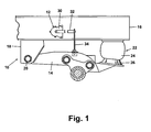
- FIG. 1 illustrates a trailing arm suspension 10 in combination with a height control valve 12 according to the invention.
- the trailing arm suspension 10 comprises a trailing arm 14 having a first end that is pivotally connected to the vehicle frame 16 through a hanger bracket 18.
- the pivotal connection is an elastomeric bushing 20.
- An air spring 22 comprising a lift bag 24 and a piston 26 is positioned between the trailing arm 14 and the frame rail 16.
- the lift bag 24 is connected to the vehicle frame 16 and the piston 26 is connected to the trailing arm 14. Pressurized air can be introduced or exhausted from the lift bag to control the relative position of the vehicle frame 16 and the trailing arm 14.
- the lift bag 24 serves to dampen the rotational movement of the trailing arm 14 about the pivotal connection 20 with the vehicle frame.
- the height control valve 12 comprises a housing 30 that is fixedly mounted to the vehicle frame 16 by bolts 31.
- a lever 32 has one end rotatably mounted to the valve 12 and the other end connected to the trailing arm 14, preferably, by way of an adjustable rod 34 extending from the trailing arm 14 to the lever 32. Movement of the trailing arm 14 about the pivotal connection 20 relative to the frame 16 causes the lever 32 to rotate relative to the valve housing 30.
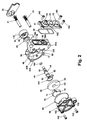
- the housing 30 comprises an interior chamber 36, open on one side, and a shaft sleeve 37 extending from the other side of the housing 30 and connecting with the interior chamber 36.
- the interior chamber is partially defined by an interior housing side wall 36A and an interior peripheral wall 36B, which extends away from the side wall 36A.
- a fluid manifold body 41A is integrally formed with the housing 30 and comprises an air supply port 38 and an air spring port 39.
- the air supply port 38 extends from the manifold body 41A and through the housing 30 to establish fluid communication with the interior chamber 36.
- the supply port has an inlet opening 38A with a relatively large rectangular cross section.
- the supply port 38 has an outlet opening 38B with a slot-like cross section in the peripheral wall 36B.
- the air spring port 39 in the housing 30 also extends from the manifold body 41A to the housing 30 to establish fluid communication with the interior chamber 36 through the side wall 36A.
- the air spring port 39 has a relatively large opening or outlet 39B near the manifold body 41A and converges to a relatively small tubular cross section inlet opening 39A that has a transverse component intersecting with the interior chamber side wall 36A.
- An exhaust port 40 extends from the exterior of the housing 30 to the shaft sleeve 37. Specifically, the exhaust port extends to an enlarged diameter portion 37A of the shaft sleeve 37.
- the shaft sleeve effectively forms part of the exhaust port.
- the air supply port 38 is adapted to fluidly connect a source of pressurized air to the interior chamber 36.
- the air spring port 39 fluidly connects the interior chamber 36 to the air spring lift bag 24.
- the exhaust port 40 fluidly connects the chamber 36 via the shaft sleeve 37 to the atmosphere.
- a modular manifold cover 41B is mounted to the housing 30 and overlies the manifold body to cover the air supply port 38 and air spring port 39.
- the manifold cover 41B includes an air supply hose connection 42 that is aligned with and provides fluid communication with the air supply port 38.
- the manifold cover 41B further includes air spring hose connections 43, 44 that are aligned with and provide fluid communication to the air spring port 39.
- the air supply hose connection 42 and air spring hose connections 43, 44 are known connectors for easily receiving hose couplings associated with the vehicle air supply and the air springs.
- a gasket 45 is provided between the manifold cover 41B and the housing 30 to enhance the fluid seal therebetween.
- the modular manifold cover 41b provides the height control valve with fluid port modularity not found in prior height control valves.
- the number and configuration of air supply port connections 42 and air spring hose connections 43, 44 can be altered by merely mounting a different cover 41B to the manifold body 41A.
- the height control valve according to the invention can easily be modified to accommodate different types of air supply connections 42 or air spring connections 43, 44.
- the number of air supply connections 42 and air spring connections 43, 44 can be altered as desired. Although, in most circumstances, only one air supply connection will be needed. Other types of air connections can be supplied instead of those connections for an air spring.
- the air connections can supply many different types of vehicle accessories, including anti-creep devices and the like.
- a shaft 48 is received within the shaft sleeve 37.
- the shaft 48 has a large diameter center portion 49 and terminates in a key 50 on one end and carries an adjustable hex head 51 toward the other end.
- a stop collar 52 is positioned between the keyed end 50 and hex head 51.
- the rounded central portion is sufficiently sized to at least partially fluidly seal the shaft with respect to the shaft sleeve 37, but not with respect to the enlarged diameter portion 37A.
- An O-ring 100 is provided to enhance the seal of the shaft relative to the housing.
- a handle seal 53 and handle cap 54 are provided to seal the shaft sleeve 37 at the exterior side of the housing 30 and provide a mating surface for the handle 32.
- the cap 54 includes a hexagonal shaft collar 55 that is sized to receive the adjustable hex head 51.
- the handle is fixedly mounted to the portion of the shaft adjacent the hex head 51.
- Multiple mounting studs 56 extend from the handle cap 54.
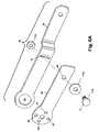
- the handle 32 comprises an inner arm 57 and an outer arm 58, which together function as the entire arm or lever for the height control valve.
- the inner arm 57 has one end in which is formed a handle cap opening 59 whose diameter is sufficiently large enough to circumscribe the multiple mounting studs 56 extending from the handle cap 54.
- the handle cap opening 59 permits the inner arm 57 to be mounted to the handle cap 54 and rotate relative thereto.
- the inner arm 57 further includes an arcuate slot 61, whose radius of curvature originates at the center line for the handle cap opening 59.
- the outer arm 58 comprises multiple openings 63 located at one end thereof and which correspond in size and spacing to the multiple mounting studs 56 of the handle cap 54.
- a bolt hole 65 is located at the opposite end of the outer arm 58 than the openings 63 and is sized to receive a traditional fastener assembly 71 comprising a bolt 71 A, washer 71B, and a nut 71C.
- the dual arm construction of the lever 32 permits the lever 32 to be rotationally adjusted relative to the shaft 48.
- the rotational adjustment is achieved by the inner arm 57 being mounted to the handle cap 54 by positioning the mounting studs 56 within the interior of the handle cap opening 59. Since the handle cap opening 59 circumscribes the mounting studs 56, the inner arm 57 is free to rotate relative to the handle cap 54.
- the outer arm 58 is mounted to the handle cap 54 such that the mounting studs 56 are received within the corresponding opening 63, which effectively fixes the position of the outer arm relative to the handle cap 54 without prohibiting the rotation of the inner arm 57 relative to the handle cap 54.
- the fastener assembly 61 is then inserted through the bolt hole 65 in the outer arm 58 and through the arcuate slot 61 of the inner arm 57.
- the fastener assembly 61 effectively limits the rotation of the inner arm 57 relative to the outer arm 58 to the are formed by the arcuate slot 61.
- the inner arm 57 is free to rotate relative to the outer arm 58 and the handle cap 54 a rotational amount equivalent to the sector cut by the arcuate slot 61.
- the outer end of the inner arm 57 opposite the end with the handle cap opening 59 can be rotated relative to the handle cap 54 and the outer arm 58 by loosening the fastening assembly 61 and rotating the inner arm 57 relative to the outer arm 58 to provide radial adjustment of the inner arm 57 with respect to the outer arm 58 and ultimately with respect to the housing 30.
- the inner arm 57 and outer arm 58 are aligned along their longitudinal axes, the inner arm 57 can be adjusted both positively and negatively with respect to the aligned longitudinal axes. Since the aligned longitudinal axes typically coincide with the horizontal axis of the vehicle in a standard mounting, the rotational adjustment of the inner arm relative to the outer arm 58 also includes a corresponding vertical adjustment with respect to the vehicle frame and trailing arm, effectively providing the height control valve with a height adjustment for the lever 32.
- the height control valve further comprises a static shear disk 60 having an axial passage in the form of an opening 62 and a fluid passage in the form of an orifice 64, both of which extend through the disk 60.
- the static shear disk 60 includes blind alignment openings 66 and 67 that receive positioning studs 68 and 69 extending from the housing 30 into the interior chamber 36 to align the static shear disk 60 relative to the housing 30 so that orifice 64 aligns with the transverse portion of the air spring port 39.
- the axial opening is sized slightly larger than the shaft 48 to ensure that fluid can flow between the shaft and the opening 62 and communicate with the outlet port 40.
- a dynamic shear disk 70 is positioned within the interior chamber 36 of the valve housing 30 in abutting relationship with the static shear disk 60.
- the dynamic shear disk 70 comprises a sector portion 72 from which extends a circular lobe 74.
- a passage in the form of a generally I-shaped recess 76 is formed in the dynamic shear disk 70 and comprises an arcuate portion 78 and a slot portion 80, which are connected by a channel 82.
- the arcuate portion 78 is predominantly located in the sector portion 72 and includes opposing outlet profile slots 84.
- An inlet profile slot 86 is provided on the exterior side of the sector portion 72 and corresponds with one of the outlet profile slots 84.
- the orifice 64 of the shear disk 60 When assembled, the orifice 64 of the shear disk 60 will lie between one of the pairs of outlet profile slots 84 and inlet profile slots 86.
- the key slot 80 is sized to slidably receive the key 50 on the shaft 48.
- the connecting slot fluidly connects the key slot 80 to the arcuate portion 78.
- a suitable resin such as an epoxy
- the resin fill eliminates any play between the key 50 and the key slot 80 so that any rotation of the shaft 48 results in an immediate and corresponding rotation of the dynamic disk 70, which improves the responsiveness and consistency of the height control valve.
- FIG. 8A illustrates an alternative construction of the dynamic disk 70.
- the alternative construction 70' is substantially identical to the dynamic disk 70 except that the connecting channel 82 does not extend into the key slot, but terminates prior to the key slot 80.
- the connecting channel 82 extend a sufficient distance to establish fluid communication with the passage 62 to thereby establish fluid communication between the exhaust port 40 and the recess 76.
- a cover 90 closes the interior chamber 36 of the housing 30 and retains the dynamic shear disk 70 and static shear disk 60 within the housing.
- An O-ring 92 is provided to enhance the seal between the cover 90 and the housing 30.
- the cover 90 comprises an annular stepped collar 94 that defines an interior recess 96 in which the dynamic shear disk 70 and static shear disk 60 are received.
- the O-ring 92 is preferably received around the periphery of the step collar 94.
- the shaft 48 is fitted with an O-ring 100 and slidably inserted into the shaft sleeve 37 until the stop collar 52 abuts the interior of the housing 30.
- the handle seal 53 and handle cap 54 are slidably mounted over the end of the shaft 48 where the hexagonal shaft collar 55 is received over the adjustable hex head 51.
- the handle 32 is mounted to the handle mount 54 as previously described and is retained with a nut threaded on the end of the shaft.
- the manifold cover 41B is affixed to the end of the housing 30 by bolts 102 extending through the manifold cover 41B and threaded into tapped openings in the housing 30.
- the gasket 45 is positioned between the manifold and the housing 30 prior to affixation of the manifold cover 41B.
- a tandem O-ring 104 is positioned within a correspondingly shaped groove 106 formed on the interior of the housing 30 and surrounding the shaft sleeve 37 and the transverse portion of the air spring port 39.
- the static shear disk 60 is positioned within the interior chamber 36 and aligned therein by inserting the alignment stud 68 into the alignment opening 66.
- the dynamic shear disk 70 is positioned in the interior chamber 36 and the key 50 of the shaft 48 is received within key slot 80 of the dynamic shear disk 70 to align the dynamic shear disk 70 relative to the shaft 48 and the shear disk 60.
- the orientation of the dynamic shear disk 70 is adjusted until the orifice 64 lies between one of the pairs of outlet profile slots 84 and inlet profile slots 86 on the dynamic shear disk. In this position, the air spring port 39 is fluidly sealed relative to the air supply port 38 and the exhaust port 40.
- the assembly of the height control valve is completed by placing the O-ring 92 on the cover 90 and positioning the cover 90 over the housing and fixing the cover 90 to the housing by threaded bolts 102 that are received within tapped openings in the housing 30.
- the static disk 60 and the dynamic disk 70 are preferably made from ceramic or any other material having suitable wear-resistant characteristics. It is within the scope of the invention for the static disk 60 not to be used and the dynamic disk would directly abut the housing. In such a configuration, the housing is preferably made from a suitable wear-resistant material. No traditional seal, an O-ring or the like, would be required between the dynamic disk and the housing.
- the height control valve begins in the neutral position.
- the dynamic shear disk 70 is oriented relative to the shear disk 60 such that the shear disk orifice 64 is positioned between the extension slot 84 and the exterior slot 86 and in abutting relationship with the dynamic shear disk 70, effectively sealing the transverse portion of the air spring port 39 and blocking fluid communication from either the air supply port 38 or exhaust port 40 to the air spring port 39.
- the lever 32 is preferably horizontally oriented.
- the lever 32 will rotate upwardly in FIG. 12 thereby rotating the shaft 48 and ultimately the dynamic shear disk 70 so that the orifice 64 moves into fluid communication with the exterior slot 86 to open the air spring port 39 to the interior chamber 36. Since the interior chamber 36 is constantly exposed to the air supply port 38, pressurized air will be directed into the air spring port 39 and introduce pressurized air into the air springs. As the air springs are inflated, the frame rail 16 and trailing arm 14 move relatively away from each other, which ultimately rotates the lever 32 and the dynamic shear disk 70 back to the neutral position.
- the lever 32 is urged downwardly, as viewed in FIG. 13, moving the dynamic shear disk 70 relative to the shear disk 60, so that the orifice 64 is moved into fluid communication with the recess 76, preferably at an extension slot 84, which is referred to as the exhaust position.
- the air spring port 39 is in fluid communication with the exhaust port 40 through the recess 76.
- the pressurized air in the air springs is exhausted through the exhaust port 40 to the atmosphere through the recess 76.
- the trailing arm 14 and the frame rail 16 move relatively towards each, which rotates the lever 32 upward and moves the extension slot 84 toward the orifice 64.
- the exhausting of the pressurized air from the air springs will continue until the orifice 64 is positioned between the extension slot 84 and the exterior slot 86.
- the spacing between the extension slot 84 and the exterior slot 86 is slightly wider than the diameter of the orifice 64. Therefore, small relative movements between the trailing arm 14 and the frame rail 16 will not result in the height control valve moving from the neutral position to either of the fill or exhaust positions. This construction is preferred so that slight weight variations or the normal operation of the suspension will not result in an adjustment of the vehicle ride height.
- the shaft 48 when assembled, the shaft 48 will extend axially through the opening 62 of the static disk 60 and the key 50 will be received within the key slot 80 on the dynamic disk 70 to thereby axially align the rotational axis of the dynamic disk 70 with the central axis of the static disk 60.
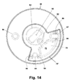
- the connecting channel 82 extends over the static disk opening 62 to establish fluid communication between the exhaust port 40 and the profile slots 84 in the arcuate portion 78 of the recess 76.
- the outlet profile slots 84 and inlet profiles 86 are radially offset a distance from the rotational axis of the dynamic disk 70 a greater distance than the opening 64 is radially offset from the central axis of the fixed disk 60.
- a result of the radially offset discrepancy between the outlet and inlet profile slots 84, 86 with respect to the opening 64 is that as the dynamic disk 70 is rotated relative to the fixed disk 60 only a corner portion of the outlet and inlet profile slots 84, 86 will initially overlie the opening 64.
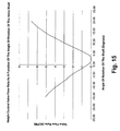
- FIG. 15 illustrates a chart showing the increasing flow rate through the aligned outlet and inlet profile slots 84, 86 as a function of the degree of rotation of the dynamic disk 70 relative to the static disk 60.
- the dynamic disk 70 is rotated a greater amount relative to the static disk 60, the greater is the cross-sectional area of either the outlet profile slot 84 or inlet profile slot 86 that overlies the opening 64.
- the control of the flow rate through the aligned profile slots and opening 64 effectively permits control over the amount of fluid that is either added or deleted from the air springs.
- This flow rate control permits the height control valve to effectively turn on at a slower rate to prevent overcompensating for smaller changes in the relative heights between the vehicle frame and the trailing arm, which correspond to smaller angular rotations of the dynamic disk 70 relative to the fixed disk 60, while still permitting appropriate response for large scale changes, which are indicated by greater rotational changes.
- the proportional flow rate feature of the valve can also be accomplished by varying the shaped of the blind openings or the air spring port in addition to or in place of the radial offset between the blind openings and the air spring port.
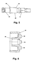
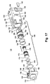
- FIGS. 16 and 17 illustrate a dump valve 110 that is particularly well suited for the port modularity functionality of the height control valve according to the invention.
- the dump valve 110 comprises a housing formed of a body 112 that defines an interior chamber 114, which is closed by a top 116 that incorporates a fluid connector 118.
- the dump valve body 112 has a manifold body surface 120 in which is formed an air spring opening 122 and an air supply opening 124.
- An air spring connector opening (not show) corresponding to the air spring opening is provided on the opposite side of the body and fluidly couples to the air spring connector of the cover.
- An exterior side surface 126 includes an exhaust opening 128 that can be covered by a resilient cover 130 which is secured to the side surface 126 by a fastener 132.
- the end of the dump valve body 112 includes four channels 134, each of which includes a detent 136.
- the cover 116 includes fingers 138 that correspond to the channels 134.
- Each of the fingers 138 include a finger 140 that is received within the detent 136 when the cover is snap-fitted to the body.
- a valve 150 is disposed within the dump valve body 112 and control fluid communication from the air spring port 122 to either the corresponding air spring connector port and the exhaust port 128.
- the valve comprises a cartridge 152 having annular grooves 154 and in which are received corresponding O-rings 156, which seal the cartridge 152 relative to the interior of the dump valve body 122 when the cartridge is inserted into the opening 114.
- An exhaust passage 160 is formed in a sidewall of the cartridge 152 as is an air spring passage 162. The exhaust passage 160 aligns with the exhaust opening 128 and the air spring passage 162 aligns with a air spring port (not shown) on the opposite side of the dump valve body 122 from the air spring opening 122.
- An annular rib (not shown) is formed on the interior of the cartridge 152 approximately at the same location of the groove 154.
- a spool 170 controls the fluid communication between the air spring opening 122 and the air spring passage 162 and exhaust passage 160.
- the spool 170 comprises adjacent pairs of annular flanges 172 and 174, which receive O-rings 176 and 178, respectively.
- a spring (not shown) extends from the opposite end of the spool 170.
- a lower O-ring 180 is provided to seal the lower end of the spool 170.
- the O-ring 176 When the spool 170 is assembled within the cartridge 152 and placed within the dump valve body 112, the O-ring 176 is disposed on the side of the interior rib nearest the exhaust opening 160 and the O-ring 178 is disposed on the side of the interior rib nearest the air spring passage 162.
- the spring biases the spool 170 such that the O-ring 176 seals against the interior rib and prevents fluid communication between air spring opening 122 and the exhaust passage 160 to thereby prevent the exhaustion through the exhaust opening 128.
- pressurized air is introduced into the connection 118 on the cover 116 of the dump valve 110.
- the pressurized air bears against the end of the spool and overcomes the force of the spring 180 to move the spool 170 away from the cover 116.
- the O-ring 176 un-seats relative to the interior annular rib and the cartridge 152 and the O-ring 178 passes over the air spring passage 176 and is positioned between the air spring passage 162 and the air spring opening 122 to thereby establish fluid communication from the air spring opening 122, through the interior the cartridge 152, through the exhaust passage 160, where the air can exhaust through the exhaust opening 128 and thereby exhaust all of the pressurized air from the air springs.
- the dump valve 110 when assembled, has a profile that is substantially identical to the manifold body 41A and the manifold cover 41B. Therefore, the dump valve 110 can be interposed between the manifold body 41A and the cover 41B and provide for a modular dump valve assembly that can be easily added to the height control valve if desired.
- the dump valve 110 When the dump valve 110 is not in the dump position, the dump valve 110 maintains fluid communication through the supply connection to the inlet port 38 and the air spring connections 43, 44 through the air supply port 39.
- An additional advantage of the dump valve 110 is that multiple manifold covers 41B can be used with the dump valve 110 in the same manner as described above with respect to the height control valve alone.
- the suspension and height control valve provide a very simple and effective means for controlling the ride height of a vehicle. Unlike prior height control valves that tended to use relatively complex plunger/piston arrangements within the various ports of the height control valve, the rotating disk structure of the height control valve 12 along with the location of the various ports provides a much simpler construction and uses parts that are not as susceptible to wear and degradation over time.
Landscapes
- Engineering & Computer Science (AREA)
- Mechanical Engineering (AREA)
- Physics & Mathematics (AREA)
- Fluid Mechanics (AREA)
- General Engineering & Computer Science (AREA)
- Vehicle Body Suspensions (AREA)
- Fluid-Damping Devices (AREA)
- Gear-Shifting Mechanisms (AREA)
- Massaging Devices (AREA)
Claims (30)
- Soupape de commande de hauteur (12) destinée à commander la hauteur relative entre un châssis de véhicule (16) et une suspension à bras tiré (10) comprenant un bras tiré (14) ayant une extrémité montée avec pivotement sur le châssis de véhicule et supportant un essieu qui monte avec possibilité de rotation des roues venant en contact avec le sol, et un ressort pneumatique (22) positionné entre une autre extrémité du bras tiré et le châssis de véhicule pour résister à la rotation du bras tiré par rapport au châssis, la soupape de commande de hauteur comprenant :un boîtier (30) comportant au moins une paroi latérale (36A) se connectant à une paroi périphérique (36B) pour définir une chambre intérieure (36),un corps de collecteur (41A) s'étendant à partir du boîtier (30) ayant une ouverture d'orifice d'entrée (38A) et une ouverture d'orifice de ressort pneumatique (39B),un module de couvercle de collecteur (41B) monté de façon amovible sur le corps de collecteur (41B) pour recouvrir l'ouverture d'orifice d'entrée (38A) et l'ouverture d'orifice de ressort pneumatique (39B), le couvercle comprenant au moins un connecteur d'alimentation en air (42) qui fournit une communication de fluide avec l'ouverture d'orifice d'entrée (38A) et au moins un connecteur de ressort pneumatique (43, 44) qui fournit une communication de fluide avec l'ouverture d'orifice de ressort pneumatique (39B),ledit boîtier (30) comprenant un orifice d'évacuation (40) s'étendant au travers d'au moins l'une desdites parois (36A, 36B) en vue d'un raccordement par fluide avec l'atmosphère, un orifice d'entrée (38) couplé par fluide à ladite ouverture d'orifice d'entrée (38A) en vue d'un raccordement par fluide à une source d'air sous pression, et un orifice de ressort pneumatique (39) couplé par fluide à ladite ouverture d'orifice de ressort pneumatique (39B) en vue d'une connexion par fluide au ressort pneumatique,un élément de soupape pouvant être entraîné en rotation (70) disposé à l'intérieur de la chambre intérieure (36) est sollicité en butée d'étanchéité vers au moins l'une desdites parois (36A, 36B) par pression de fluide introduite dans ladite chambre intérieure (36) par l'intermédiaire dudit orifice d'entrée (38), ledit élément de soupape pouvant être entraîné en rotation (70) ayant des passages de commande (82, 84, 86) agencés sur celui-ci de sorte que lors de la rotation, la soupape de commande de hauteur (12) peut être sélectivement activée entre une position de remplissage où l'orifice de ressort pneumatique (39) est relié par fluide à l'orifice d'entrée (38) pour introduire de l'air sous pression provenant de la source d'air dans le ressort pneumatique, une position d'évacuation où l'orifice de ressort pneumatique (39) est relié par fluide à l'orifice d'évacuation (40) pour évacuer l'air sous pression depuis le ressort pneumatique, et une position neutre où l'orifice de ressort pneumatique (39) est déconnecté par fluide à la fois depuis l'orifice d'entrée (38) et depuis l'orifice d'évacuation (40), afin de commander ainsi l'introduction et l'évacuation de l'air depuis le ressort pneumatique afin de faire tourner le bras tiré par rapport au châssis du véhicule et de régler la hauteur du châssis du véhicule.
- Soupape de commande de hauteur selon la revendication 1, dans laquelle la soupape est caractérisée par l'élément de soupape pouvant être entraîné en rotation (70) qui est disposé à l'intérieur de la chambre intérieure et séparant par fluide l'orifice d'entrée et l'orifice d'évacuation, l'élément de soupape pouvant être entraîné en rotation ayant un passage de commande (78, 82, 84, 86) qui relie sélectivement par fluide l'orifice de ressort pneumatique à l'orifice d'entrée ou à l'orifice de sortie lors de la rotation de l'élément de soupape pouvant être entraîné en rotation, et l'élément de soupape pouvant être entraîné en rotation étant sollicité en butée d'étanchéité par rapport au boîtier par la pression provenant de l'air sous pression.
- Soupape de commande de hauteur selon la revendication 2, dans laquelle le boîtier comprend une première partie de paroi (36A) à partir de laquelle s'étend une seconde partie de paroi (36B) afin de définir partiellement la chambre intérieure, l'orifice de ressort pneumatique et l'orifice d'évacuation sont positionnés sur la première partie de paroi et l'orifice d'entrée est positionné sur la seconde partie de paroi, l'élément de soupape pouvant être entraîne en rotation comprend un disque (70) ayant un premier et second côtés opposés reliés par un bord périphérique, le premier côté du disque vient en contact avec la première partie de paroi et recouvre l'orifice de ressort pneumatique et l'orifice d'évacuation et le second côté fait face à l'orifice d'entrée où l'air sous pression entrant dans l'orifice d'entrée sollicite le premier côté de disque contre la première partie de paroi pour fermer de façon étanche l'orifice de ressort pneumatique et l'orifice d'évacuation par rapport à l'orifice d'entrée.
- Soupape de commande de hauteur selon la revendication 3, dans laquelle le passage de commande comprend des première (86) et seconde (84) ouvertures borgnes espacées formées dans le premier côté du disque et une paroi de séparation formée par la partie du disque disposé entre les ouvertures borgnes, où la soupape est dans la position neutre, la paroi de séparation recouvre l'orifice de ressort pneumatique pour empêcher la communication de fluide entre l'orifice de ressort pneumatique et soit l'orifice d'évacuation, soit l'orifice d'entrée, lorsque le disque est entraîné en rotation dans une première direction de rotation depuis la position neutre, la première ouverture borgne est en communication de fluide avec l'orifice d'entrée et l'orifice de ressort pneumatique pour placer la soupape dans la position de remplissage, lorsque le disque est entraîné en rotation dans une seconde direction de rotation, opposée à la première direction de rotation, depuis la position neutre, le disque ayant la seconde ouverture borgne est en communication de fluide avec l'orifice d'évacuation et l'orifice de ressort pneumatique pour placer la soupape dans la position d'évacuation.
- Soupape de commande de hauteur selon la revendication 4, dans laquelle les première et seconde ouvertures borgnes sont mises en forme de sorte qu'une surface en section transversale croissante des première et seconde ouvertures borgnes est exposée à l'orifice de ressort pneumatique lorsque la soupape est déplacée de la position neutre vers les positions de remplissage et d'évacuation, respectivement, pour fournir un débit d'air croissant en fonction du degré de rotation du disque.
- Soupape de commande de hauteur selon la revendication 4, dans laquelle les première et seconde ouvertures borgnes sont positionnées sur le disque par rapport à l'ouverture de ressort pneumatique, de sorte qu'une surface en section transversale croissante des première et seconde ouvertures borgnes est exposée à l'orifice de ressort pneumatique lorsque la soupape est déplacée depuis la position neutre vers les positions de remplissage et d'évacuation, respectivement, pour fournir un débit d'air croissant en fonction du degré de rotation du disque.
- Soupape de commande de hauteur selon les revendications 4 à 6, et comprenant en outre un disque statique (60) positionné entre la première partie de paroi et le disque pouvant être entraîné en rotation et couplé à la première partie de paroi, le disque statique ayant un passage d'évacuation (62) s'étendant au travers du disque et en communication de fluide avec l'orifice d'évacuation et un passage de ressort pneumatique (64) s'étendant en travers du disque et en communication de fluide avec l'orifice de ressort pneumatique, où la paroi de séparation recouvre le passage de ressort pneumatique lorsque la soupape se trouve dans la position neutre, la première ouverture borgne recouvre une partie du passage de ressort pneumatique lorsque la soupape est dans la position de remplissage, et la seconde ouverture borgne recouvre une partie du passage de ressort pneumatique lorsque la soupape est dans la position d'évacuation.
- Soupape de commande de hauteur selon les revendications 4 à 7, dans laquelle la première ouverture borgne s'étend depuis la paroi de séparation vers la paroi périphérique du disque, de sorte que la première ouverture borne est toujours en communication de fluide avec l'orifice d'entrée.
- Soupape de commande de hauteur selon les revendications 4 à 8, dans laquelle la seconde ouverture borgne s'étend depuis la paroi de séparation vers l'orifice d'évacuation, de sorte que la seconde ouverture borgne est toujours en communication de fluide avec l'orifice d'évacuation.
- Soupape de commande de hauteur selon la revendication 9, dans laquelle le boîtier comprend une ouverture d'axe (68) s'étendant au travers de la première partie de paroi, l'ouverture d'axe forme une partie de l'ouverture d'évacuation, et la seconde ouverture borgne est en communication de fluide avec l'ouverture d'axe.
- Soupape de commande de hauteur selon la revendication 10 et comprenant en outre un axe (48) s'étendant au travers de l'ouverture d'axe et fixée au disque, grâce à quoi la rotation de l'axe entraîne en rotation le disque pouvant être entraîné en rotation pour placer la soupape dans les positions neutre, de remplissage ou d'évacuation.
- Soupape de commande de hauteur selon la revendication 11, dans laquelle le disque pouvant être entraîné en rotation comprend une rainure (80) et l'axe comprend une clavette (50) reçue à l'intérieur de la rainure pour relier l'axe et le disque pouvant être entraîné en rotation.
- Soupape de commande de hauteur selon la revendication 12 et comprenant en outre une résine disposée à l'intérieur de la rainure pour remplir des espaces quelconques entre la clavette et la rainure.
- Soupape de commande de hauteur selon la revendication 11 à 13, comprenant en outre un levier (32) ayant une première extrémité reliée à l'axe et une autre extrémité adaptée pour être reliée au bras tiré, grâce à quoi la rotation du bras tiré déplace le levier pour entraîner ainsi en rotation l'axe et déplacer la soupape entre les positions neutre, de remplissage et d'évacuation.
- Soupape de commande de hauteur selon la revendication 14, dans laquelle le levier comprend des premier (58) et second (57) bras allongés, le premier bras comporte une première extrémité montée de façon fixe sur l'axe, le second bras comporte une première extrémité adaptée pour être reliée au bras tiré, et le second bras peut être réglé avec possibilité de rotation par rapport au premier bras pour prévoir un ajustement de la hauteur du levier par rapport au bras tiré.
- Soupape de commande de hauteur selon la revendication 15, dans laquelle le premier bras comprend une ouverture (65), le second bras comporte une autre extrémité qui est montée avec possibilité de rotation sur l'axe et une rainure en forme d'axe (61) qui s'aligne avec une première ouverture de bras, et un dispositif de fixation libérable (71) s'étendant au travers de la première ouverture de bras et la seconde rainure en forme d'arc de bras pour permettre le positionnement en rotation sélectif du second bras par rapport au premier bras pour ajuster la hauteur du levier.
- Soupape de commande de hauteur selon la revendication 1, dans laquelle le couvercle de collecteur comprend en outre un connecteur d'accessoire (44) destiné à connecter par fluide un accessoire de véhicule à la chambre de ressort pneumatique.
- soupape de commande de hauteur selon la revendication 17 et comprenant en outre une soupape de décharge modulaire (110) montée de façon amovible entre le corps de collecteur et le couvercle de collecteur afin de relier par fluide l'orifice de ressort pneumatique à l'orifice d'évacuation pour évacuer l'air sous pression depuis le ressort pneumatique indépendamment de la position de la soupape de commande de hauteur.
- Soupape de commande de hauteur selon la revendication 18, dans laquelle la soupape de décharge comprend un boîtier (112, 116) comportant un passage d'entrée (124) qui relie par fluide le connecteur d'alimentation en air à la chambre d'entrée, un orifice d'évacuation (128), un passage de ressort pneumatique (122) reliant par fluide la chambre de ressort pneumatique au connecteur de ressort pneumatique et l'orifice d'évacuation de soupape de décharge, et une soupape (150) positionnée à l'intérieur du passage de ressort pneumatique, afin de relier sélectivement par fluide la chambre de ressort pneumatique au connecteur de ressort pneumatique et entre le connecteur de ressort pneumatique et l'orifice d'évacuation de soupape de décharge pour évacuer l'air sous pression des ressorts pneumatiques.
- Soupape de commande de hauteur selon la revendication 19, dans laquelle le passage de ressort pneumatique comprend une chambre de décharge (114) formée à l'intérieur du boîtier et reliée par fluide à l'orifice d'évacuation de soupape de décharge, la chambre de décharge comportant une première ouverture reliée par fluide à la chambre de ressort pneumatique et une seconde ouverture reliée par fluide au connecteur de ressort pneumatique, et la soupape est une soupape à tiroir pouvant être actionnée entre une première position où les première et seconde ouvertures sont reliées par fluide et une seconde position où la première ouverture est reliée par fluide à l'orifice d'évacuation de soupape de décharge.
- Soupape de commande de hauteur selon la revendication 1 à 13 et 17 à 20 caractérisée par un levier (32) ayant une première extrémité couplée de façon fonctionnelle à la soupape pour déplacer sélectivement la soupape entre les positions de remplissage, d'évacuation et neutre et une autre extrémité conçue pour être reliée au bras tiré, grâce à quoi la rotation du bras tiré déplace le levier pour déplacer ainsi la soupape entre les positions neutre, de remplissage et d'évacuation.
- Soupape de commande de hauteur selon la revendication 21, dans laquelle la soupape comprend un élément de soupape mobile (70) et le levier comprend des premier et second bras allongés, le premier bras comporte une première extrémité couplée de façon fixe à l'élément de soupape mobile, le second bras comporte une première extrémité conçue pour être reliée au bras tiré, et le second bras peut être ajusté avec possibilité de rotation par rapport au premier bras pour fournir l'ajustement de la hauteur du levier par rapport au bras tiré.
- Soupape de commande de hauteur selon la revendication 22 , dans laquelle le premier bras comporte une ouverture (65), le second bras comporte une autre extrémité qui est ancrée avec possibilité de rotation par rapport au premier bras et une rainure en forme d'arc (61) qui s'aligne avec la première ouverture de bras, et un dispositif de fixation libérable (71) s'étendant au travers de la première ouverture de bras et la seconde rainure en forme d'arc de bras pour permettre le positionnement en rotation sélective du second bras par rapport au premier bras pour ajuster la hauteur du levier.
- Soupape de commande de hauteur selon la revendication 1 à 4 et 17 à 23, dans laquelle la soupape est caractérisée par un élément de soupape mobile (70) ayant un passage de commande (78, 82, 84, 86) mobile entre une première position où le passage de commande relie par fluide l'orifice de ressort pneumatique à l'orifice d'entrée pour placer la soupape dans une position de remplissage, une seconde position où le passage de commande relie par fluide l'orifice de ressort pneumatique à l'orifice d'évacuation pour placer la soupape dans la position d'évacuation, et une troisième position où le passage de commande n'est pas en communication de fluide avec soit l'orifice d'entrée, soit l'orifice d'évacuation pour placer la soupape dans la position neutre, et le passage de commande présente une surface en section transversale croissante à l'orifice de ressort pneumatique lorsque la soupape est déplacée soit vers la position de remplissage, soit vers la position d'évacuation pour fournir un débit d'air qui augmente en fonction du degré de déplacement de l'élément mobile.
- Soupape de commande de hauteur selon la revendication 24, dans laquelle le boîtier comprend une première partie de paroi à partir de laquelle s'étend une seconde partie de paroi pour définir partiellement la chambre intérieure, l'orifice de ressort pneumatique et l'orifice d'évacuation sont positionnés sur la première partie de paroi, l'orifice d'entrée est positionné sur la seconde partie de paroi, l'élément de soupape mobile comprend un disque pouvant être entraîné en rotation (70) ayant des premier et second côtés opposés reliés par un bord périphérique, le premier côté du disque recouvre l'orifice de ressort pneumatique et l'orifice d'évacuation et le second côté fait face à l'orifice d'entrée, de sorte que l'air sous pression entrant dans la chambre au travers de l'orifice d'entrée sollicite le premier côté du disque contre la première partie de paroi pour fermer de façon étanche l'orifice de ressort pneumatique et l'orifice d'évacuation par rapport à l'orifice d'entrée.
- Soupape de commande de hauteur selon la revendication 25, dans laquelle le passage de commande comprend des première (86) et seconde (84) ouvertures borgnes espacées, formées dans le premier côté du disque et la partie du disque disposée entre les ouvertures borgnes forme une paroi de séparation, les première et seconde ouvertures borgnes sont mises en forme de sorte qu'une surface en section transversale croissante des première et seconde ouvertures borgnes est exposée à l'orifice de ressort pneumatique lorsque la soupape est déplacée de la position neutre vers les positions de remplissage d'évacuation, respectivement.
- Soupape de commande de hauteur selon la revendication 26, dans laquelle le passage de commande comprend des première (86) et seconde (84) ouvertures borgnes espacées, formées dans le premier côté du disque et la partie du disque disposée entre les ouvertures borgnes forme une paroi de séparation, les première et seconde ouvertures borgnes sont positionnées sur le disque de sorte qu'une surface en section transversale croissante des première et seconde ouvertures borgnes est exposée à l'orifice de ressort pneumatique lorsque la soupape est déplacée de la position neutre aux positions de remplissage et d'évacuation, respectivement, pour fournir le débit d'air qui augmente en fonction du degré de rotation du disque.
- Soupape de commande de hauteur selon la revendication 27, dans laquelle les première et seconde ouvertures borgnes sont espacées d'une distance radiale différente d'un axe de rotation du disque par rapport à l'orifice de ressort pneumatique.
- Soupape de commande de hauteur selon les revendication 1 et 17 à 28 et caractérisée en outre par un axe (48) s'étendant au travers du boîtier comportant une clavette (50), la soupape comprend en outre un élément de soupape pouvant être entraîné en rotation (70) ayant une rainure (80) qui reçoit la clavette de l'axe et une résine est disposée à l'intérieur de la rainure pour remplir les espaces quelconques entre la clavette et la rainure, où la rotation de l'axe fait tourner l'élément de soupape pouvant être entraîné en rotation pour relier sélectivement par fluide l'orifice de ressort pneumatique à l'orifice d'entrée et l'orifice d'évacuation pour placer la soupape dans les positions de remplissage et d'évacuation respectivement.
- Soupape de commande de hauteur selon la revendication 29, dans laquelle l'élément de soupape pouvant être entraîné en rotation est sollicité en butée d'étanchéité par rapport au boîtier par la pression provenant de l'air sous pression.
Priority Applications (1)
| Application Number | Priority Date | Filing Date | Title |
|---|---|---|---|
| EP05002868A EP1533150A3 (fr) | 1999-08-24 | 2000-08-24 | Suspension à bras longitudinaux comprenant un distributeur de commande de réglage en hauteur |
Applications Claiming Priority (3)
| Application Number | Priority Date | Filing Date | Title |
|---|---|---|---|
| US15062199P | 1999-08-24 | 1999-08-24 | |
| US150621P | 1999-08-24 | ||
| PCT/US2000/023278 WO2001014156A1 (fr) | 1999-08-24 | 2000-08-24 | Suspension de bras longitudinal et sa soupape de commande de hauteur |
Related Child Applications (1)
| Application Number | Title | Priority Date | Filing Date |
|---|---|---|---|
| EP05002868A Division EP1533150A3 (fr) | 1999-08-24 | 2000-08-24 | Suspension à bras longitudinaux comprenant un distributeur de commande de réglage en hauteur |
Publications (2)
| Publication Number | Publication Date |
|---|---|
| EP1214210A1 EP1214210A1 (fr) | 2002-06-19 |
| EP1214210B1 true EP1214210B1 (fr) | 2006-10-25 |
Family
ID=22535342
Family Applications (1)
| Application Number | Title | Priority Date | Filing Date |
|---|---|---|---|
| EP00959363A Expired - Lifetime EP1214210B1 (fr) | 1999-08-24 | 2000-08-24 | Soupape de commande de hauteur pour suspension de bras longitudinal |
Country Status (10)
| Country | Link |
|---|---|
| US (1) | US7028996B2 (fr) |
| EP (1) | EP1214210B1 (fr) |
| CN (2) | CN100475581C (fr) |
| AT (1) | ATE343489T1 (fr) |
| AU (1) | AU7069900A (fr) |
| CA (1) | CA2382787C (fr) |
| DE (1) | DE60031554T2 (fr) |
| ES (1) | ES2274804T3 (fr) |
| MX (1) | MXPA02001907A (fr) |
| WO (1) | WO2001014156A1 (fr) |
Cited By (3)
| Publication number | Priority date | Publication date | Assignee | Title |
|---|---|---|---|---|
| US10814691B2 (en) | 2016-02-18 | 2020-10-27 | Haldex Brake Products Aktiebolag | Mechanically actuated leveling valve mechanism |
| US11207935B2 (en) | 2016-02-18 | 2021-12-28 | Haldex Brake Products Aktiebolag | Electronic control device and control circuit for an air suspension system of a commercial vehicle |
| EP4596268A1 (fr) * | 2024-02-02 | 2025-08-06 | ZF CV Systems Europe BV | Vanne de nivellement de cabine et système, véhicule utilitaire, procédé d'assemblage d'une vanne de nivellement de cabine et utilisation d'une vanne de nivellement de cabine |
Families Citing this family (33)
| Publication number | Priority date | Publication date | Assignee | Title |
|---|---|---|---|---|
| ATE344739T1 (de) * | 2000-05-25 | 2006-11-15 | Haldex Brake Corp | Sensor für ein niveauregelsystem |
| AU2002305698B2 (en) * | 2001-05-25 | 2007-06-07 | Haldex Brake Corporation | Trailing arm suspension and height control system with motorized valve therefor |
| US7204478B2 (en) * | 2002-08-07 | 2007-04-17 | Haldex Brake Corporation | Height control valve with universal mounting for a suspension system |
| EP1943115B8 (fr) * | 2005-11-04 | 2010-07-21 | Hendrickson International Corporation | Valve de commande de hauteur pour système de suspension d'essieu de véhicule |
| DE102007005979A1 (de) * | 2007-02-07 | 2008-08-21 | Knorr-Bremse Systeme für Nutzfahrzeuge GmbH | Pneumatische Schaltventileinrichtung für luftgefederte Fahrzeuge mit mechanischer Rückstellung des Bedienelements |
| US20080252025A1 (en) * | 2007-04-12 | 2008-10-16 | Plath Victor A | Electronic height control system for a vehicle with multiple input signals |
| US10836232B2 (en) | 2007-04-12 | 2020-11-17 | Haldex Brake Products Corporation | Electronic height control system for a vehicle with multiple input signals |
| EP2006131B1 (fr) * | 2007-06-21 | 2013-03-20 | Barksdale, Inc. | Contrôle vertical d'une ressort pneumatique |
| US7918466B2 (en) | 2007-06-21 | 2011-04-05 | Barksdale, Inc. | Vertical air bag control |
| US7959165B2 (en) * | 2008-12-02 | 2011-06-14 | Watson & Chalin Manufacturing, Inc. | Suspension system run height adjustment |
| DE102009007691B3 (de) † | 2009-02-05 | 2010-08-05 | Knorr-Bremse Systeme für Nutzfahrzeuge GmbH | Niveauregelventil mit druckbelasteter Ventilscheibe |
| US7887065B2 (en) * | 2009-02-24 | 2011-02-15 | Hadley Products | Height control valve for vehicle leveling system |
| KR100973332B1 (ko) * | 2009-08-25 | 2010-07-30 | 김석환 | 공기식 현가시스템의 차체높이 다중 조절장치 |
| CN101670762B (zh) * | 2009-09-25 | 2011-04-20 | 中国北方车辆研究所 | 高度调节阀 |
| US8453669B2 (en) * | 2010-07-21 | 2013-06-04 | Masco Corporation Of Indiana | Waterway adapter |
| US8690127B2 (en) * | 2011-05-09 | 2014-04-08 | James C. Patterman, III | Vehicle lift system accessory |
| CA2836136C (fr) * | 2011-06-14 | 2016-07-26 | Hendrickson Usa, L.L.C. | Ensemble soupape de reglage de hauteur pour systemes essieu/suspension |
| DE102013100245A1 (de) * | 2013-01-11 | 2014-07-17 | Knorr-Bremse Systeme für Nutzfahrzeuge GmbH | Ventil und Verfahren zum Zusammenfügen eines Ventils |
| DE102013100247A1 (de) * | 2013-01-11 | 2014-07-17 | Knorr-Bremse Systeme für Nutzfahrzeuge GmbH | Ventil, Ventilvorrichtung und Verfahren zum Zusammenfügen einer Ventilvorrichtung |
| DE102013100243A1 (de) * | 2013-01-11 | 2014-07-17 | Knorr-Bremse Systeme für Nutzfahrzeuge GmbH | Ventilgehäuse und Verfahren zum Montieren eines Ventilgehäuses |
| US8973922B2 (en) * | 2013-03-15 | 2015-03-10 | Haldex Brake Products Corporation | Air suspension height control valve with dual ride height positions |
| EP2806194B1 (fr) * | 2013-05-21 | 2018-01-03 | WABCO Europe BVBA | Vanne de mise à niveau pour décharge et alimentation en fluide |
| DE112014004144T5 (de) * | 2013-09-10 | 2016-07-07 | Firestone Industrial Products Company, Llc | Füllventilhalterung für ein Luftfederungssystem an einem Fahrzeug |
| US10479159B2 (en) | 2016-04-04 | 2019-11-19 | Barksdale, Inc. | Ride height leveling with selectable configurations: system and method |
| EP3401134B1 (fr) * | 2017-05-08 | 2020-04-01 | WABCO Europe BVBA | Vanne de mise à niveau pour décharge et alimentation en fluide |
| CN107725830B (zh) * | 2017-11-01 | 2019-07-19 | 琪舰消防工程有限责任公司 | 基于伯努利原理的消防栓的自伸缩控制方法 |
| US10753420B2 (en) * | 2018-04-16 | 2020-08-25 | Beijingwest Industries Co., Ltd. | Rotating three way valve for switchable air springs |
| CN110953375B (zh) * | 2019-11-25 | 2024-09-17 | 上海三一重机股份有限公司 | 一种换向阀及挖掘机 |
| EP3848211B1 (fr) * | 2020-01-08 | 2024-05-08 | ZF CV Systems Europe BV | Agencement de soupape de commande de suspension pour un système de suspension pneumatique d'un véhicule utilitaire |
| FR3126037A1 (fr) * | 2021-08-09 | 2023-02-10 | Sera Ingenierie | Système de leurrage massique à roues élastiquement déformables |
| US20240051364A1 (en) * | 2022-08-10 | 2024-02-15 | Universal Air, Inc. | Air bag suspension |
| EP4375172A1 (fr) | 2022-11-28 | 2024-05-29 | Volvo Truck Corporation | Dispositif de commande d'alimentation en air pour véhicule poids lourd comprenant un essieu relevable |
| CN119712767A (zh) * | 2024-12-24 | 2025-03-28 | 中国重汽集团济南动力有限公司 | 驾驶室空气悬挂高度调节阀 |
Family Cites Families (30)
| Publication number | Priority date | Publication date | Assignee | Title |
|---|---|---|---|---|
| US1555199A (en) * | 1923-06-11 | 1925-09-29 | Marie Julia Track | Vehicle with pneumatic suspension |
| US2790650A (en) * | 1955-02-22 | 1957-04-30 | Gomma Antivibranti Applic | Pneumatic load-responsive spring suspension for vehicles |
| US2905430A (en) | 1956-03-16 | 1959-09-22 | Firestone Tire & Rubber Co | Control device for vehicle pneumatic suspension systems |
| US2964311A (en) * | 1957-04-12 | 1960-12-13 | Weatherhead Co | Air spring control valve |
| US2910305A (en) | 1957-04-15 | 1959-10-27 | Weatherhead Co | Pneumatic suspension for vehicles and control valve therefor |
| US2948549A (en) * | 1957-10-11 | 1960-08-09 | Midland Ross Corp | Fluid suspension system for vehicles |
| US3083059A (en) * | 1958-11-13 | 1963-03-26 | Hercules Galion Prod Inc | Automatic tilting dump truck stabilizer |
| US3104114A (en) * | 1959-03-25 | 1963-09-17 | Dawson Vogel Engineering Compa | Control system for vehicle suspension |
| DE1144125B (de) * | 1961-07-13 | 1963-02-21 | Boge Gmbh | Drehschiebergesteuerter Hoehenregler zur Regelung von mit einem Fluid arbeitenden Federungen, insbesondere fuer Kraftfahrzeuge |
| BE754551A (fr) * | 1969-08-11 | 1971-01-18 | Scovill Manufacturing Co | Soupape de commande de dispositif de regulation automatique d'assiette pour vehicules |
| DE3045690A1 (de) * | 1979-06-29 | 1982-07-08 | Volkswagenwerk Ag, 3180 Wolfsburg | Federung fuer kraftfahrzeuge mit einer niveauregeleinrichtung |
| DE3008150A1 (de) * | 1980-03-04 | 1981-09-17 | Wabco Fahrzeugbremsen Gmbh, 3000 Hannover | Luftfederventil |
| DE3542974A1 (de) | 1985-12-05 | 1987-06-11 | Wabco Westinghouse Fahrzeug | Niveauregeleinrichtung fuer fahrzeuge mit luftfedern |
| DE3542975A1 (de) | 1985-12-05 | 1987-06-11 | Wabco Westinghouse Fahrzeug | Niveauregeleinrichtung fuer fahrzeuge mit luftfedern |
| JPH0671850B2 (ja) * | 1988-10-31 | 1994-09-14 | マツダ株式会社 | 車高調整装置 |
| US4976104A (en) | 1988-12-22 | 1990-12-11 | Gt Development Corporation | Combined switch and valve for compressor powered inflatable |
| DE3917458A1 (de) | 1989-05-30 | 1990-12-06 | Wabco Westinghouse Fahrzeug | Niveauregeleinrichtung fuer fahrzeuge |
| US5161817A (en) | 1990-10-16 | 1992-11-10 | Imo Industries Inc. | Fluid-operated leveling valve systems |
| DE4114861A1 (de) | 1991-05-07 | 1992-11-12 | Wabco Westinghouse Fahrzeug | Fahrzeug mit liftbarer nachlaufachse |
| US5161579A (en) | 1991-06-06 | 1992-11-10 | Hadley Products, Division Of Nelson Metal Products, Corp. | Leveling valve for air springs |
| FR2687350B1 (fr) * | 1992-02-14 | 1994-04-29 | Wabco Westinghouse Equip Autom | Valve d'echappement et d'alimentation de fluide, notamment valve de nivellement pour suspension pneumatique et systeme de suspension utilisant de telles valves. |
| US5375819A (en) | 1992-11-10 | 1994-12-27 | Nai Neway, Inc. | Dual in-line height control valve assembly |
| DE4243577B4 (de) | 1992-12-22 | 2004-02-05 | Wabco Gmbh & Co. Ohg | Mit Druckmittel arbeitende Niveauregeleinrichtung |
| DE4317847B4 (de) | 1993-05-28 | 2007-07-19 | Wabco Gmbh | Einrichtung zum Steuern der Schleppachse eines Fahrzeugs |
| AU6943394A (en) * | 1994-05-03 | 1995-11-29 | Nai Neway, Inc. | Height control valve with dump valve |
| US5560591A (en) | 1995-05-02 | 1996-10-01 | Hadley Products | Leveling valve for air springs |
| JP3394357B2 (ja) * | 1995-05-10 | 2003-04-07 | Ntn株式会社 | カムシャフト |
| US5651555A (en) * | 1995-11-13 | 1997-07-29 | Barksdale, Inc. | Fluid-operated leveling valve systems |
| US5860450A (en) * | 1997-07-17 | 1999-01-19 | Hadley Products Corporation | Height control valve for vehicle leveling system |
| US6089551A (en) | 1998-02-10 | 2000-07-18 | Crowe Manufacturing Services, Inc. | Height control valve with integral dump device |
-
2000
- 2000-08-24 CN CNB200410046533XA patent/CN100475581C/zh not_active Expired - Lifetime
- 2000-08-24 AT AT00959363T patent/ATE343489T1/de not_active IP Right Cessation
- 2000-08-24 ES ES00959363T patent/ES2274804T3/es not_active Expired - Lifetime
- 2000-08-24 CA CA002382787A patent/CA2382787C/fr not_active Expired - Lifetime
- 2000-08-24 AU AU70699/00A patent/AU7069900A/en not_active Abandoned
- 2000-08-24 MX MXPA02001907A patent/MXPA02001907A/es active IP Right Grant
- 2000-08-24 DE DE60031554T patent/DE60031554T2/de not_active Expired - Fee Related
- 2000-08-24 CN CNB008136513A patent/CN1187206C/zh not_active Expired - Lifetime
- 2000-08-24 EP EP00959363A patent/EP1214210B1/fr not_active Expired - Lifetime
- 2000-08-24 WO PCT/US2000/023278 patent/WO2001014156A1/fr not_active Ceased
-
2002
- 2002-08-07 US US10/214,036 patent/US7028996B2/en not_active Expired - Lifetime
Cited By (3)
| Publication number | Priority date | Publication date | Assignee | Title |
|---|---|---|---|---|
| US10814691B2 (en) | 2016-02-18 | 2020-10-27 | Haldex Brake Products Aktiebolag | Mechanically actuated leveling valve mechanism |
| US11207935B2 (en) | 2016-02-18 | 2021-12-28 | Haldex Brake Products Aktiebolag | Electronic control device and control circuit for an air suspension system of a commercial vehicle |
| EP4596268A1 (fr) * | 2024-02-02 | 2025-08-06 | ZF CV Systems Europe BV | Vanne de nivellement de cabine et système, véhicule utilitaire, procédé d'assemblage d'une vanne de nivellement de cabine et utilisation d'une vanne de nivellement de cabine |
Also Published As
| Publication number | Publication date |
|---|---|
| DE60031554T2 (de) | 2007-08-16 |
| AU7069900A (en) | 2001-03-19 |
| CN1377315A (zh) | 2002-10-30 |
| US7028996B2 (en) | 2006-04-18 |
| MXPA02001907A (es) | 2003-10-14 |
| US20030038412A1 (en) | 2003-02-27 |
| CN100475581C (zh) | 2009-04-08 |
| ATE343489T1 (de) | 2006-11-15 |
| CA2382787A1 (fr) | 2001-03-01 |
| ES2274804T3 (es) | 2007-06-01 |
| EP1214210A1 (fr) | 2002-06-19 |
| CA2382787C (fr) | 2008-10-14 |
| CN1187206C (zh) | 2005-02-02 |
| CN1565876A (zh) | 2005-01-19 |
| WO2001014156A1 (fr) | 2001-03-01 |
| DE60031554D1 (de) | 2006-12-07 |
Similar Documents
| Publication | Publication Date | Title |
|---|---|---|
| EP1214210B1 (fr) | Soupape de commande de hauteur pour suspension de bras longitudinal | |
| EP2778484B1 (fr) | Soupape de commande de hauteur de suspension pneumatique à deux positions de la hauteur d'assiette | |
| JP3120859B2 (ja) | 切り替え可能なロール・スタビライザバー | |
| JPH0313366Y2 (fr) | ||
| US6698730B2 (en) | Dual rate air spring | |
| US7204478B2 (en) | Height control valve with universal mounting for a suspension system | |
| JPH0313365Y2 (fr) | ||
| US20010015224A1 (en) | Fluid flow valve with variable flow rate | |
| EP1109686B1 (fr) | Suspension de vehicule avec soupape rotative de commande de hauteur | |
| JPS61122015A (ja) | 車両のサスペンシヨン | |
| US20230122679A1 (en) | Integrated air supply unit | |
| US5333645A (en) | Height control valve and dump valve therefor | |
| JPH0514646B2 (fr) | ||
| EP1533150A2 (fr) | Suspension à bras longitudinaux comprenant un distributeur de commande de réglage en hauteur | |
| EP0705175A1 (fr) | Soupape de commande de la hauteur a bague reglable | |
| US4660810A (en) | Change-over valve for air suspension | |
| WO1995029823A1 (fr) | Soupape de regulation de hauteur comportant une soupape de decharge | |
| JPS633477Y2 (fr) | ||
| JPS61122017A (ja) | 車両のサスペンシヨン | |
| JPH0244120Y2 (fr) | ||
| JPS61125906A (ja) | 車両のサスペンシヨン | |
| JPH048244B2 (fr) |
Legal Events
| Date | Code | Title | Description |
|---|---|---|---|
| PUAI | Public reference made under article 153(3) epc to a published international application that has entered the european phase |
Free format text: ORIGINAL CODE: 0009012 |
|
| 17P | Request for examination filed |
Effective date: 20020322 |
|
| AK | Designated contracting states |
Kind code of ref document: A1 Designated state(s): AT BE CH CY DE DK ES FI FR GB GR IE IT LI LU MC NL PT SE |
|
| AX | Request for extension of the european patent |
Free format text: AL PAYMENT 20020325;LT PAYMENT 20020325;LV PAYMENT 20020325;MK PAYMENT 20020325;RO PAYMENT 20020325;SI PAYMENT 20020325 |
|
| 17Q | First examination report despatched |
Effective date: 20031124 |
|
| RAP1 | Party data changed (applicant data changed or rights of an application transferred) |
Owner name: HALDEX BRAKE CORPORATION |
|
| GRAP | Despatch of communication of intention to grant a patent |
Free format text: ORIGINAL CODE: EPIDOSNIGR1 |
|
| RTI1 | Title (correction) |
Free format text: HEIGHT CONTROL VALVE FOR TRAILING ARM SUSPENSION |
|
| GRAS | Grant fee paid |
Free format text: ORIGINAL CODE: EPIDOSNIGR3 |
|
| GRAA | (expected) grant |
Free format text: ORIGINAL CODE: 0009210 |
|
| AK | Designated contracting states |
Kind code of ref document: B1 Designated state(s): AT BE CH CY DE DK ES FI FR GB GR IE IT LI LU MC NL PT SE |
|
| PG25 | Lapsed in a contracting state [announced via postgrant information from national office to epo] |
Ref country code: CH Free format text: LAPSE BECAUSE OF FAILURE TO SUBMIT A TRANSLATION OF THE DESCRIPTION OR TO PAY THE FEE WITHIN THE PRESCRIBED TIME-LIMIT Effective date: 20061025 Ref country code: LI Free format text: LAPSE BECAUSE OF FAILURE TO SUBMIT A TRANSLATION OF THE DESCRIPTION OR TO PAY THE FEE WITHIN THE PRESCRIBED TIME-LIMIT Effective date: 20061025 Ref country code: NL Free format text: LAPSE BECAUSE OF FAILURE TO SUBMIT A TRANSLATION OF THE DESCRIPTION OR TO PAY THE FEE WITHIN THE PRESCRIBED TIME-LIMIT Effective date: 20061025 Ref country code: BE Free format text: LAPSE BECAUSE OF FAILURE TO SUBMIT A TRANSLATION OF THE DESCRIPTION OR TO PAY THE FEE WITHIN THE PRESCRIBED TIME-LIMIT Effective date: 20061025 Ref country code: AT Free format text: LAPSE BECAUSE OF FAILURE TO SUBMIT A TRANSLATION OF THE DESCRIPTION OR TO PAY THE FEE WITHIN THE PRESCRIBED TIME-LIMIT Effective date: 20061025 Ref country code: FI Free format text: LAPSE BECAUSE OF FAILURE TO SUBMIT A TRANSLATION OF THE DESCRIPTION OR TO PAY THE FEE WITHIN THE PRESCRIBED TIME-LIMIT Effective date: 20061025 |
|
| REG | Reference to a national code |
Ref country code: GB Ref legal event code: FG4D |
|
| REG | Reference to a national code |
Ref country code: CH Ref legal event code: EP |
|
| REG | Reference to a national code |
Ref country code: IE Ref legal event code: FG4D |
|
| REF | Corresponds to: |
Ref document number: 60031554 Country of ref document: DE Date of ref document: 20061207 Kind code of ref document: P |
|
| PG25 | Lapsed in a contracting state [announced via postgrant information from national office to epo] |
Ref country code: DK Free format text: LAPSE BECAUSE OF FAILURE TO SUBMIT A TRANSLATION OF THE DESCRIPTION OR TO PAY THE FEE WITHIN THE PRESCRIBED TIME-LIMIT Effective date: 20070125 Ref country code: SE Free format text: LAPSE BECAUSE OF FAILURE TO SUBMIT A TRANSLATION OF THE DESCRIPTION OR TO PAY THE FEE WITHIN THE PRESCRIBED TIME-LIMIT Effective date: 20070125 |
|
| PG25 | Lapsed in a contracting state [announced via postgrant information from national office to epo] |
Ref country code: PT Free format text: LAPSE BECAUSE OF FAILURE TO SUBMIT A TRANSLATION OF THE DESCRIPTION OR TO PAY THE FEE WITHIN THE PRESCRIBED TIME-LIMIT Effective date: 20070326 |
|
| NLV1 | Nl: lapsed or annulled due to failure to fulfill the requirements of art. 29p and 29m of the patents act | ||
| ET | Fr: translation filed | ||
| REG | Reference to a national code |
Ref country code: CH Ref legal event code: PL |
|
| REG | Reference to a national code |
Ref country code: ES Ref legal event code: FG2A Ref document number: 2274804 Country of ref document: ES Kind code of ref document: T3 |
|
| PLBE | No opposition filed within time limit |
Free format text: ORIGINAL CODE: 0009261 |
|
| STAA | Information on the status of an ep patent application or granted ep patent |
Free format text: STATUS: NO OPPOSITION FILED WITHIN TIME LIMIT |
|
| 26N | No opposition filed |
Effective date: 20070726 |
|
| PG25 | Lapsed in a contracting state [announced via postgrant information from national office to epo] |
Ref country code: MC Free format text: LAPSE BECAUSE OF NON-PAYMENT OF DUE FEES Effective date: 20070831 Ref country code: GR Free format text: LAPSE BECAUSE OF FAILURE TO SUBMIT A TRANSLATION OF THE DESCRIPTION OR TO PAY THE FEE WITHIN THE PRESCRIBED TIME-LIMIT Effective date: 20070126 |
|
| PG25 | Lapsed in a contracting state [announced via postgrant information from national office to epo] |
Ref country code: IE Free format text: LAPSE BECAUSE OF NON-PAYMENT OF DUE FEES Effective date: 20070824 |
|
| PGFP | Annual fee paid to national office [announced via postgrant information from national office to epo] |
Ref country code: DE Payment date: 20080831 Year of fee payment: 9 Ref country code: ES Payment date: 20080731 Year of fee payment: 9 |
|
| PGFP | Annual fee paid to national office [announced via postgrant information from national office to epo] |
Ref country code: FR Payment date: 20080716 Year of fee payment: 9 Ref country code: IT Payment date: 20080813 Year of fee payment: 9 |
|
| PGFP | Annual fee paid to national office [announced via postgrant information from national office to epo] |
Ref country code: GB Payment date: 20080718 Year of fee payment: 9 |
|
| PG25 | Lapsed in a contracting state [announced via postgrant information from national office to epo] |
Ref country code: CY Free format text: LAPSE BECAUSE OF FAILURE TO SUBMIT A TRANSLATION OF THE DESCRIPTION OR TO PAY THE FEE WITHIN THE PRESCRIBED TIME-LIMIT Effective date: 20061025 Ref country code: LU Free format text: LAPSE BECAUSE OF NON-PAYMENT OF DUE FEES Effective date: 20070824 |
|
| GBPC | Gb: european patent ceased through non-payment of renewal fee |
Effective date: 20090824 |
|
| REG | Reference to a national code |
Ref country code: FR Ref legal event code: ST Effective date: 20100430 |
|
| PG25 | Lapsed in a contracting state [announced via postgrant information from national office to epo] |
Ref country code: DE Free format text: LAPSE BECAUSE OF NON-PAYMENT OF DUE FEES Effective date: 20100302 Ref country code: FR Free format text: LAPSE BECAUSE OF NON-PAYMENT OF DUE FEES Effective date: 20090831 |
|
| REG | Reference to a national code |
Ref country code: ES Ref legal event code: FD2A Effective date: 20090825 |
|
| PG25 | Lapsed in a contracting state [announced via postgrant information from national office to epo] |
Ref country code: GB Free format text: LAPSE BECAUSE OF NON-PAYMENT OF DUE FEES Effective date: 20090824 |
|
| PG25 | Lapsed in a contracting state [announced via postgrant information from national office to epo] |
Ref country code: IT Free format text: LAPSE BECAUSE OF NON-PAYMENT OF DUE FEES Effective date: 20090824 |
|
| PG25 | Lapsed in a contracting state [announced via postgrant information from national office to epo] |
Ref country code: ES Free format text: LAPSE BECAUSE OF NON-PAYMENT OF DUE FEES Effective date: 20090825 |