EP1215539A2 - Appareil et méthode de contrôle d'enregistrement et de qualité d'image dans une machine xérographique en tandem avec transfert et fixage simultanés - Google Patents
Appareil et méthode de contrôle d'enregistrement et de qualité d'image dans une machine xérographique en tandem avec transfert et fixage simultanés Download PDFInfo
- Publication number
- EP1215539A2 EP1215539A2 EP01129024A EP01129024A EP1215539A2 EP 1215539 A2 EP1215539 A2 EP 1215539A2 EP 01129024 A EP01129024 A EP 01129024A EP 01129024 A EP01129024 A EP 01129024A EP 1215539 A2 EP1215539 A2 EP 1215539A2
- Authority
- EP
- European Patent Office
- Prior art keywords
- velocity
- members
- controlling
- transfuse
- controller
- Prior art date
- Legal status (The legal status is an assumption and is not a legal conclusion. Google has not performed a legal analysis and makes no representation as to the accuracy of the status listed.)
- Granted
Links
Images

Classifications
-
- G—PHYSICS
- G03—PHOTOGRAPHY; CINEMATOGRAPHY; ANALOGOUS TECHNIQUES USING WAVES OTHER THAN OPTICAL WAVES; ELECTROGRAPHY; HOLOGRAPHY
- G03G—ELECTROGRAPHY; ELECTROPHOTOGRAPHY; MAGNETOGRAPHY
- G03G15/00—Apparatus for electrographic processes using a charge pattern
- G03G15/14—Apparatus for electrographic processes using a charge pattern for transferring a pattern to a second base
- G03G15/16—Apparatus for electrographic processes using a charge pattern for transferring a pattern to a second base of a toner pattern, e.g. a powder pattern, e.g. magnetic transfer
- G03G15/1605—Apparatus for electrographic processes using a charge pattern for transferring a pattern to a second base of a toner pattern, e.g. a powder pattern, e.g. magnetic transfer using at least one intermediate support
-
- G—PHYSICS
- G03—PHOTOGRAPHY; CINEMATOGRAPHY; ANALOGOUS TECHNIQUES USING WAVES OTHER THAN OPTICAL WAVES; ELECTROGRAPHY; HOLOGRAPHY
- G03G—ELECTROGRAPHY; ELECTROPHOTOGRAPHY; MAGNETOGRAPHY
- G03G2215/00—Apparatus for electrophotographic processes
- G03G2215/01—Apparatus for electrophotographic processes for producing multicoloured copies
- G03G2215/0103—Plural electrographic recording members
- G03G2215/0119—Linear arrangement adjacent plural transfer points
-
- G—PHYSICS
- G03—PHOTOGRAPHY; CINEMATOGRAPHY; ANALOGOUS TECHNIQUES USING WAVES OTHER THAN OPTICAL WAVES; ELECTROGRAPHY; HOLOGRAPHY
- G03G—ELECTROGRAPHY; ELECTROPHOTOGRAPHY; MAGNETOGRAPHY
- G03G2215/00—Apparatus for electrophotographic processes
- G03G2215/16—Transferring device, details
- G03G2215/1676—Simultaneous toner image transfer and fixing
- G03G2215/1695—Simultaneous toner image transfer and fixing at the second or higher order transfer point
Definitions
- This invention relates to electrophotographic printing. More specifically, this invention relates to electrophotographic printers which include a transfusing member.
- Electrophotographic marking is a well known and commonly used method of copying or printing original documents. Electrophotographic marking is typically performed by exposing a light image of an original document onto a substantially uniformly charged photoreceptor. In response to that light image, the photoreceptor discharges so as to create an electrostatic latent image, thereby forming a toner powder image. That toner powder image is then transferred from the photoreceptor, either directly, or after an intermediate transfer step, onto a marking substrate such as a sheet of paper. The transferred toner powder image is then fused to the marking substrate using heat and/or pressure. The surface of the photoreceptor is then cleaned of residual developing material and recharged in preparation for the creation of another image.
- Electrophotographic marking can also produce color images by repeating the above process once for each color that makes the color image.
- the charged photoconductive surface may be exposed to a light image which represents a first color, say cyan (C) .
- the resultant electrostatic latent image can then be developed with cyan toner particles to produce a cyan image which is subsequently transferred to a marking substrate.
- the foregoing process can then be repeated for a second color, say magenta (M), then a third color, say yellow (Y), and finally a fourth color, say black (B).
- M magenta
- Y say yellow
- B fourth color
- the color printing process described above superimposes the various color toner powder images directly onto a marking substrate.
- Another electrophotographic color printing process uses an intermediate transfer member or belt (ITB).
- ITB intermediate transfer member or belt
- successive toner images are transferred in superimposed registration from the photoreceptor onto the ITB. Only after the composite toner image is formed on the ITB is that image transferred and fused onto the marking substrate, e.g., paper.
- the most common developing materials are dry powder toners. Dry powder developers are typically comprised of not only toner particles but also of carrier granules. The toner particles triboelectrically adhere to the carrier granules until the toner particles are attracted onto the latent image.
- An alternative 'to dry powder developing materials are liquid developers. Liquid developers, also referred to a liquid inks, have a liquid carrier into which toner particles are dispersed. When developing with liquid developers both the toner particles and the liquid carrier are advanced into contact with the electrostatic latent image. The liquid carrier is then removed by blotting, evaporation, or by some other means, leaving the toner particles behind.
- ITBs can also be used in the fusing process. ITBs which are used in fusing are referred to herein as transfusing members or belts (TB), and the combined processes of transferring and fusing is called transfusing. Transfusing is highly desirable since the size and cost of transfusing printing machines can be less than comparable printing machines which use a separate transfer station and fusing station. Other advantages such as improved image quality can also be obtained by transfusing. Members are usually pinched between one or more contact rollers and a backup roller such that a fusing pressure is created between the nip of the backup roller and the transfusing member and heat is applied to the toner image. The combination of heat and pressure causes the toner image to fuse onto the marking substrate.
- velocity control e.g. by servo systems
- ITB interleaved toner
- the interface between the photoreceptor drum and the ITB is a slip interface.
- the motion of the four photoreceptors (C,M,Y,B) and the ITB can be independently controlled by separate servo systems.
- the transfuse belt is a very sticky belt, no slip in the transfer nip between the ITB and TB is possible. Due to variations in encoding and mechanical tolerances, two different velocity measurements will be produced. If two different servo systems are used, they will have conflicting requirements. This makes independent velocity control of ITB and transfuse belt impossible.
- An apparatus comprises first and second members having engaged and disengaged modes; a first velocity controller for controlling the velocity of the first member when it is disengaged from the second member; a second velocity controller for controlling the velocity of the second member when it is disengaged from the first member; one of said controllers commonly controlling both of said members when they are engaged.
- a process comprises controlling the velocity of a first member; independently controlling the velocity of a second member when said first and second members are mutually disengaged; and commonly controlling the velocity of said members when said members are engaged.
- Xerographic apparatus comprises at least one photoreceptor module; an image transfer member engaging said module; a transfuse member engagable and disengagable with said image transfer member; an image transfer member servo controller controlling the velocity of said image member when said members are disengaged; a transfuse member servo controller controlling the velocity of said transfuse member when said members are disengaged, one of said controllers controlling both of said members when they are mutually engaged.
- the one controller comprises the image transfer member servo.
- the remaining controller provides drive to its respective member.
- the drive is just about enough make up for the additional load on the one controller due to the additionally driven member during engagement.
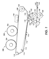
- Fig. 1 shows photoreceptor modules 100 and 102. Although two modules are shown, for monochrome reproduction only one is needed, while for color reproduction there are normally three or four modules present.
- each module comprises a charging station having at least one corona generator, an imaging station having a raster scanner, a developing station, etc., (none shown), which are respectively disposed around photoconductor coated drums 104 and 106.
- belts could be used in place of drums 104 and 106.
- Drums 104 and 106 engage an image transfer member such as an ITB 108 which is driven by an ITB drive roller 110 in the direction indicated by arrow 112 in order to form an image on ITB 108.
- roller 110 is driven by a motor (shown in Fig. 2) and has a shaft encoder (also shown in Fig. 2), e.g., an optical tachometer, coupled to it.
- a shaft encoder also shown in Fig. 2
- ITB 108 engages a tensioning roller 114, which is movable in the directions indicated by an arrow 115 to adjust the tension in ITB 108.
- an image 116 on the ITB 108 which is due to the action of at least one of modules 100 and 102, passes an idler roller 118 and enters a transfer nip 120 comprising a transfer roller 122 in order to transfer image 116 onto a transfuse member such as a TB 124.
- Roller 122 is mounted so that it can move as indicated by arrow 123 in order to engage or disengage ITB 108 with TB 124. ITB 108 then passes a TB drive roller 126, a steering roller 128, and to remove image 116 a cleaning station 130. ITB 108 then returns to modules 100 and 102 to receive a new image. It will be appreciated that any one or more of rollers 110, 114, 118, 120, 128 or some other roller (not shown), could also be drive rollers for ITB 108 and that the shaft encoder (shown in Fig. 2) could also be on any of these rollers, not necessarily on whichever roller is the drive roller.
- TB 124 passes over a TB transfer roller 122 in the direction indicated by arrow 132.
- TB 124 then goes around an idler roller 134 and enters a transfuse nip 136 comprising an idler roller 134 and a transfuse roller 138.
- Roller 138 is mounted so that it can move as indicated by arrow 140 in order to disengage rollers 134 and 138 when the apparatus is not in use to prevent flat spots thereon.
- Image 116 is transfused onto a paper 142, which is also entering nip 136 as indicated by an arrow 144. Paper 142 then emerges from nip 136 with image 116 on it due to heat and/or pressure applied by rollers 134 and 138.
- TB 124 then goes to a cleaning station 146 in order to remove the image thereon.
- a drive roller 147 Disposed opposite cleaning station 146 is a drive roller 147, which is coupled to a motor (shown in Fig. 2) in order to drive TB 124.
- a shaft encoder (shown in Fig. 2) is also coupled to roller 147.
- TB 124 then goes to a tensioning roller 148 which is movable as indicated by arrow 150 in order to adjust the tension of TB 124. Thereafter TB 124 returns to nip 120 to receive a new image.
- rollers 123, 134, 140, 147, 150, or some other roller could also be drive rollers for TB 124 and that the shaft encoder could be on any of these rollers, not necessarily whichever roller is the drive roller. It will be further appreciated that ITB 108 and TB 124 could also comprise drums or rollers.
- ITB loop 200 comprises a subtractor 206 which receives at its positive input a signal representing the ITB 108 velocity setpoint on line 208 from controller 204 and at its negative input a signal representing measured ITB 108 velocity on line 210.
- the output difference error signal is applied to an ITB velocity servo controller 212.
- the output signal from controller 212 is applied to motor drive amplifier (MDA) 214 and also to the negative input of subtractor 216.
- MDA motor drive amplifier
- a motor 218 receives the output signal from MDA 214, and in turn, drives roller 110 and thus ITB 108.
- a shaft encoder 219 provides the measured ITB 108 velocity signal on line 210.
- the subtractor 216 receives at its positive input a voltage setpoint signal on line 220 provided by controller 220.
- the output difference signal is applied to a voltage servo controller 222, which provides an output signal to torque assist contact 224 of switch 226.
- TB loop 202 comprises a subtractor 228 which receives at its positive input a signal representing a TB 124 velocity setpoint on line 230 from controller 204 and at its negative input a signal representing measured TB 124 velocity on line 232.
- the output error difference signal is applied to a TB velocity servo controller 229.
- Controllers 212 and 229 can be any standard type as known in the art, e.g., type CMC 502 manufactured by Cleveland Controls Co.
- the output signal from controller 229 is applied to a velocity mode contact 234 of switch 226. If switch 226 is in the velocity mode, then this signal is further applied to an MDA 236.
- the output signal from MDA 236 is applied to a motor 238, which drives roller 147 and thus TB 124.
- a shaft encoder 239 provides the measured TB 124 velocity signal on line 232.
- transfer nip 120 is initially disengaged, and controller 204 initially sets switch 226 in the velocity mode and provides the two velocity setpoint signals and the voltage setpoint signal.
- Each loop 200 and 202 operates independently to respectively control ITB 108 and TB 124, as known in the art.
- transfer nip 124 is engaged, and loop 200 continues to operate as a velocity control loop.
- controller 204 sets switch 226 in its torque assist mode so that MDA 236 receives its input from controller 222. The result is that loop 200 controls not only motor 218 and ITB 108, but also motor 238 and TB 124.
- motor 238 provides just about enough torque (as determined by setpoint voltage on line 220) to make up for the additional load of TB 124 placed upon motor 218.
- torque as determined by setpoint voltage on line 220
Landscapes
- Physics & Mathematics (AREA)
- General Physics & Mathematics (AREA)
- Electrostatic Charge, Transfer And Separation In Electrography (AREA)
- Control Or Security For Electrophotography (AREA)
- Color Electrophotography (AREA)
- Fixing For Electrophotography (AREA)
- Combination Of More Than One Step In Electrophotography (AREA)
Applications Claiming Priority (2)
| Application Number | Priority Date | Filing Date | Title |
|---|---|---|---|
| US736986 | 1991-07-29 | ||
| US09/736,986 US6400913B1 (en) | 2000-12-14 | 2000-12-14 | Control registration and motion quality of a tandem xerographic machine using transfuse |
Publications (3)
| Publication Number | Publication Date |
|---|---|
| EP1215539A2 true EP1215539A2 (fr) | 2002-06-19 |
| EP1215539A3 EP1215539A3 (fr) | 2006-02-15 |
| EP1215539B1 EP1215539B1 (fr) | 2008-05-21 |
Family
ID=24962138
Family Applications (1)
| Application Number | Title | Priority Date | Filing Date |
|---|---|---|---|
| EP01129024A Expired - Lifetime EP1215539B1 (fr) | 2000-12-14 | 2001-12-06 | Appareil de contrôle d'enregistrement et de qualité d'image dans une machine xérographique en tandem avec transfert et fixage simultanés |
Country Status (4)
| Country | Link |
|---|---|
| US (1) | US6400913B1 (fr) |
| EP (1) | EP1215539B1 (fr) |
| JP (1) | JP4121738B2 (fr) |
| DE (1) | DE60134111D1 (fr) |
Families Citing this family (41)
| Publication number | Priority date | Publication date | Assignee | Title |
|---|---|---|---|---|
| JP2002229295A (ja) * | 2001-02-06 | 2002-08-14 | Konica Corp | 画像形成装置及び画像形成装置におけるモータの制御方法 |
| JP2003091201A (ja) * | 2001-09-18 | 2003-03-28 | Fuji Xerox Co Ltd | 画像形成装置および定着装置 |
| JP2004145260A (ja) * | 2002-07-04 | 2004-05-20 | Ricoh Co Ltd | 定着装置・画像形成装置・記録媒体の再生方法 |
| US6731891B1 (en) * | 2003-06-13 | 2004-05-04 | Xerox Corproation | Transfer roll engagement method for minimizing motion quality disturbances |
| US7711301B2 (en) * | 2006-03-10 | 2010-05-04 | Ricoh Company, Ltd. | Image transfer device for image forming apparatus |
| US7931274B2 (en) * | 2009-05-29 | 2011-04-26 | Xerox Corporation | Hybrid control of sheet transport modules |
| US10632740B2 (en) | 2010-04-23 | 2020-04-28 | Landa Corporation Ltd. | Digital printing process |
| US8020864B1 (en) | 2010-05-27 | 2011-09-20 | Xerox Corporation | Printing system and method using alternating velocity and torque control modes for operating one or more select sheet transport devices to avoid contention |
| JP5831183B2 (ja) * | 2011-12-02 | 2015-12-09 | 富士ゼロックス株式会社 | クリーニング装置及びこれを用いた画像形成装置 |
| WO2013132418A2 (fr) | 2012-03-05 | 2013-09-12 | Landa Corporation Limited | Procédé d'impression numérique |
| CN104271687B (zh) | 2012-03-05 | 2016-11-02 | 兰达公司 | 油墨膜构造 |
| US10642198B2 (en) | 2012-03-05 | 2020-05-05 | Landa Corporation Ltd. | Intermediate transfer members for use with indirect printing systems and protonatable intermediate transfer members for use with indirect printing systems |
| US10569534B2 (en) | 2012-03-05 | 2020-02-25 | Landa Corporation Ltd. | Digital printing system |
| US9498946B2 (en) | 2012-03-05 | 2016-11-22 | Landa Corporation Ltd. | Apparatus and method for control or monitoring of a printing system |
| US9902147B2 (en) | 2012-03-05 | 2018-02-27 | Landa Corporation Ltd. | Digital printing system |
| US9643403B2 (en) | 2012-03-05 | 2017-05-09 | Landa Corporation Ltd. | Printing system |
| US10434761B2 (en) | 2012-03-05 | 2019-10-08 | Landa Corporation Ltd. | Digital printing process |
| CN109177531B (zh) | 2012-03-15 | 2020-11-27 | 兰达公司 | 打印系统的环形柔性皮带 |
| JP5949323B2 (ja) * | 2012-08-23 | 2016-07-06 | 富士ゼロックス株式会社 | 清掃器および画像形成装置 |
| GB201401173D0 (en) | 2013-09-11 | 2014-03-12 | Landa Corp Ltd | Ink formulations and film constructions thereof |
| GB2536489B (en) | 2015-03-20 | 2018-08-29 | Landa Corporation Ltd | Indirect printing system |
| GB2537813A (en) | 2015-04-14 | 2016-11-02 | Landa Corp Ltd | Apparatus for threading an intermediate transfer member of a printing system |
| US9488935B1 (en) * | 2015-09-25 | 2016-11-08 | Lexmark International, Inc. | Drive mechanism for an intermediate transfer member module of an electrophotographic imaging device |
| GB201602877D0 (en) | 2016-02-18 | 2016-04-06 | Landa Corp Ltd | System and method for generating videos |
| GB201609463D0 (en) | 2016-05-30 | 2016-07-13 | Landa Labs 2012 Ltd | Method of manufacturing a multi-layer article |
| DE112017002714T5 (de) | 2016-05-30 | 2019-02-28 | Landa Corporation Ltd. | Digitales Druckverfahren |
| WO2019077489A1 (fr) | 2017-10-19 | 2019-04-25 | Landa Corporation Ltd. | Courroie flexible sans fin pour un système d'impression |
| JP7225230B2 (ja) | 2017-11-19 | 2023-02-20 | ランダ コーポレイション リミテッド | デジタル印刷システム |
| WO2019102297A1 (fr) | 2017-11-27 | 2019-05-31 | Landa Corporation Ltd. | Système d'impression numérique |
| US11707943B2 (en) | 2017-12-06 | 2023-07-25 | Landa Corporation Ltd. | Method and apparatus for digital printing |
| US11679615B2 (en) | 2017-12-07 | 2023-06-20 | Landa Corporation Ltd. | Digital printing process and method |
| WO2020003088A1 (fr) | 2018-06-26 | 2020-01-02 | Landa Corporation Ltd. | Élément de transfert intermédiaire pour système d'impression numérique |
| US10994528B1 (en) | 2018-08-02 | 2021-05-04 | Landa Corporation Ltd. | Digital printing system with flexible intermediate transfer member |
| US12001902B2 (en) | 2018-08-13 | 2024-06-04 | Landa Corporation Ltd. | Correcting distortions in digital printing by implanting dummy pixels in a digital image |
| JP7246496B2 (ja) | 2018-10-08 | 2023-03-27 | ランダ コーポレイション リミテッド | 印刷システムおよび方法に関する摩擦低減手段 |
| WO2020136517A1 (fr) | 2018-12-24 | 2020-07-02 | Landa Corporation Ltd. | Système d'impression numérique |
| EP3946953A4 (fr) | 2019-03-31 | 2022-12-14 | Landa Corporation Ltd. | Systèmes et procédés pour empêcher ou minimiser les défauts d'impression dans les processus d'impression |
| CN114746813A (zh) | 2019-11-25 | 2022-07-12 | 兰达公司 | 在数字印刷中使用红外辐射来干燥油墨 |
| US11321028B2 (en) | 2019-12-11 | 2022-05-03 | Landa Corporation Ltd. | Correcting registration errors in digital printing |
| EP4081866A4 (fr) | 2019-12-29 | 2024-01-03 | Landa Corporation Ltd. | Procédé et système d'impression |
| EP4264377A4 (fr) | 2021-02-02 | 2024-11-13 | Landa Corporation Ltd. | Atténuation de distorsions dans des images imprimées |
Family Cites Families (13)
| Publication number | Priority date | Publication date | Assignee | Title |
|---|---|---|---|---|
| JPS5753759A (en) * | 1980-09-17 | 1982-03-30 | Ricoh Co Ltd | Speed controller of electronic photographic copying machine |
| US4847660A (en) * | 1985-10-25 | 1989-07-11 | Colorocs Corporation | Method and apparatus for registration control in an electrophotographic print engine |
| US5200782A (en) | 1991-11-01 | 1993-04-06 | Xerox Corporation | Disturbance isolation in a belt receptor of a color printer |
| JP3351435B2 (ja) | 1992-07-17 | 2002-11-25 | 富士ゼロックス株式会社 | 多重画像形成装置におけるカラーレジストレーションずれの補正方法 |
| US5384592A (en) | 1992-11-16 | 1995-01-24 | Xerox Corporation | Method and apparatus for tandem color registration control |
| US5387962A (en) | 1993-12-13 | 1995-02-07 | Xerox Corporation | Self-aligning roll for belt loop modules |
| US5508789A (en) | 1994-11-22 | 1996-04-16 | Xerox Corporation | Apparatus and method to control and calibrate deliberate speed mismatch in color IOTs |
| JP3460425B2 (ja) * | 1995-03-16 | 2003-10-27 | 富士ゼロックス株式会社 | 画像形成装置 |
| US5689764A (en) * | 1995-05-24 | 1997-11-18 | Ricoh Company, Ltd. | Image forming apparatus and device for driving a contact type charging member |
| US5708950A (en) | 1995-12-06 | 1998-01-13 | Xerox Corporation | Transfuser |
| US5837408A (en) | 1997-08-20 | 1998-11-17 | Xerox Corporation | Xerocolography tandem architectures for high speed color printing |
| US5991565A (en) * | 1997-12-16 | 1999-11-23 | Konica Corporation | Fixing device |
| US6088565A (en) * | 1998-12-23 | 2000-07-11 | Xerox Corporation | Buffered transfuse system |
-
2000
- 2000-12-14 US US09/736,986 patent/US6400913B1/en not_active Expired - Lifetime
-
2001
- 2001-12-06 DE DE60134111T patent/DE60134111D1/de not_active Expired - Lifetime
- 2001-12-06 EP EP01129024A patent/EP1215539B1/fr not_active Expired - Lifetime
- 2001-12-07 JP JP2001373795A patent/JP4121738B2/ja not_active Expired - Fee Related
Also Published As
| Publication number | Publication date |
|---|---|
| EP1215539B1 (fr) | 2008-05-21 |
| JP2002214867A (ja) | 2002-07-31 |
| JP4121738B2 (ja) | 2008-07-23 |
| EP1215539A3 (fr) | 2006-02-15 |
| DE60134111D1 (de) | 2008-07-03 |
| US6400913B1 (en) | 2002-06-04 |
| US20020076227A1 (en) | 2002-06-20 |
Similar Documents
| Publication | Publication Date | Title |
|---|---|---|
| US6400913B1 (en) | Control registration and motion quality of a tandem xerographic machine using transfuse | |
| US7706731B2 (en) | Hybrid printing system | |
| EP1096332B1 (fr) | Dispositif de formation d'image | |
| US6352806B1 (en) | Low toner pile height color image reproduction machine | |
| US6434345B2 (en) | Image forming apparatus | |
| US8121505B2 (en) | Hybrid printing system | |
| US20110008077A1 (en) | Scalable printing system having multiple intermediate transfer belts | |
| HK77396A (en) | Liquid developer systems for imaging on transparent and opaque substrates | |
| US5440382A (en) | Transfer material carrying controlling apparatus | |
| JP3738124B2 (ja) | 多色画像形成装置 | |
| JP2000338741A (ja) | 画像形成装置 | |
| JPH04333868A (ja) | 画像形成装置 | |
| JP7823007B2 (ja) | 画像形成装置 | |
| JPH0466970A (ja) | カラープリンタ | |
| JPH0443372A (ja) | 画像形成装置 | |
| JP3799245B2 (ja) | 画像形成装置 | |
| US6377766B1 (en) | Electrophotographic apparatus having a printing density controller for dropout and non-dropout color | |
| JP3002267B2 (ja) | 記録装置 | |
| JP2002365874A (ja) | 画像形成装置 | |
| JP2697963B2 (ja) | カラー複写機 | |
| JP2001188420A (ja) | 画像形成装置 | |
| JP2005195647A (ja) | 転写装置 | |
| JPH1124339A (ja) | 画像形成方法及び装置並びに記録媒体 | |
| JPH05107902A (ja) | 記録装置 | |
| JPH09106194A (ja) | 画像形成装置 |
Legal Events
| Date | Code | Title | Description |
|---|---|---|---|
| PUAI | Public reference made under article 153(3) epc to a published international application that has entered the european phase |
Free format text: ORIGINAL CODE: 0009012 |
|
| AK | Designated contracting states |
Kind code of ref document: A2 Designated state(s): AT BE CH CY DE DK ES FI FR GB GR IE IT LI LU MC NL PT SE TR |
|
| AX | Request for extension of the european patent |
Free format text: AL;LT;LV;MK;RO;SI |
|
| PUAL | Search report despatched |
Free format text: ORIGINAL CODE: 0009013 |
|
| AK | Designated contracting states |
Kind code of ref document: A3 Designated state(s): AT BE CH CY DE DK ES FI FR GB GR IE IT LI LU MC NL PT SE TR |
|
| AX | Request for extension of the european patent |
Extension state: AL LT LV MK RO SI |
|
| 17P | Request for examination filed |
Effective date: 20060816 |
|
| AKX | Designation fees paid |
Designated state(s): DE FR GB |
|
| 17Q | First examination report despatched |
Effective date: 20061006 |
|
| GRAP | Despatch of communication of intention to grant a patent |
Free format text: ORIGINAL CODE: EPIDOSNIGR1 |
|
| RTI1 | Title (correction) |
Free format text: APPARATUS FOR CONTROL OF REGISTRATION AND PICTURE QUALITY IN A TANDEM XEROGRAPHIC MACHINE USING A TRANSFUSE SYSTEM |
|
| GRAS | Grant fee paid |
Free format text: ORIGINAL CODE: EPIDOSNIGR3 |
|
| GRAA | (expected) grant |
Free format text: ORIGINAL CODE: 0009210 |
|
| AK | Designated contracting states |
Kind code of ref document: B1 Designated state(s): DE FR GB |
|
| REG | Reference to a national code |
Ref country code: GB Ref legal event code: FG4D |
|
| REF | Corresponds to: |
Ref document number: 60134111 Country of ref document: DE Date of ref document: 20080703 Kind code of ref document: P |
|
| PLBE | No opposition filed within time limit |
Free format text: ORIGINAL CODE: 0009261 |
|
| STAA | Information on the status of an ep patent application or granted ep patent |
Free format text: STATUS: NO OPPOSITION FILED WITHIN TIME LIMIT |
|
| 26N | No opposition filed |
Effective date: 20090224 |
|
| REG | Reference to a national code |
Ref country code: FR Ref legal event code: PLFP Year of fee payment: 15 |
|
| REG | Reference to a national code |
Ref country code: FR Ref legal event code: PLFP Year of fee payment: 16 |
|
| PGFP | Annual fee paid to national office [announced via postgrant information from national office to epo] |
Ref country code: DE Payment date: 20161121 Year of fee payment: 16 Ref country code: FR Payment date: 20161121 Year of fee payment: 16 Ref country code: GB Payment date: 20161128 Year of fee payment: 16 |
|
| REG | Reference to a national code |
Ref country code: DE Ref legal event code: R119 Ref document number: 60134111 Country of ref document: DE |
|
| GBPC | Gb: european patent ceased through non-payment of renewal fee |
Effective date: 20171206 |
|
| REG | Reference to a national code |
Ref country code: FR Ref legal event code: ST Effective date: 20180831 |
|
| PG25 | Lapsed in a contracting state [announced via postgrant information from national office to epo] |
Ref country code: FR Free format text: LAPSE BECAUSE OF NON-PAYMENT OF DUE FEES Effective date: 20180102 Ref country code: DE Free format text: LAPSE BECAUSE OF NON-PAYMENT OF DUE FEES Effective date: 20180703 |
|
| PG25 | Lapsed in a contracting state [announced via postgrant information from national office to epo] |
Ref country code: GB Free format text: LAPSE BECAUSE OF NON-PAYMENT OF DUE FEES Effective date: 20171206 |