EP1216778A1 - Dispositif de purification de liquides d'usinage pour machines à életroérosion - Google Patents
Dispositif de purification de liquides d'usinage pour machines à életroérosion Download PDFInfo
- Publication number
- EP1216778A1 EP1216778A1 EP00128317A EP00128317A EP1216778A1 EP 1216778 A1 EP1216778 A1 EP 1216778A1 EP 00128317 A EP00128317 A EP 00128317A EP 00128317 A EP00128317 A EP 00128317A EP 1216778 A1 EP1216778 A1 EP 1216778A1
- Authority
- EP
- European Patent Office
- Prior art keywords
- particles
- machining
- liquid
- settling tank
- ultrasonic
- Prior art date
- Legal status (The legal status is an assumption and is not a legal conclusion. Google has not performed a legal analysis and makes no representation as to the accuracy of the status listed.)
- Granted
Links
- 239000007788 liquid Substances 0.000 title claims description 49
- 239000002245 particle Substances 0.000 claims abstract description 67
- 238000003754 machining Methods 0.000 claims abstract description 40
- 239000000654 additive Substances 0.000 claims abstract description 12
- 230000000996 additive effect Effects 0.000 claims abstract description 11
- 238000000354 decomposition reaction Methods 0.000 claims abstract description 5
- 238000001914 filtration Methods 0.000 claims description 12
- 238000002156 mixing Methods 0.000 claims description 10
- OKTJSMMVPCPJKN-UHFFFAOYSA-N Carbon Chemical compound [C] OKTJSMMVPCPJKN-UHFFFAOYSA-N 0.000 claims description 9
- 238000011109 contamination Methods 0.000 claims description 9
- 229910052799 carbon Inorganic materials 0.000 claims description 7
- 238000010908 decantation Methods 0.000 claims description 7
- 239000000725 suspension Substances 0.000 claims description 5
- 238000000605 extraction Methods 0.000 claims description 4
- 239000000203 mixture Substances 0.000 claims description 2
- 239000012530 fluid Substances 0.000 abstract description 5
- 239000013528 metallic particle Substances 0.000 abstract 1
- 238000000746 purification Methods 0.000 description 7
- 239000002184 metal Substances 0.000 description 5
- 238000002604 ultrasonography Methods 0.000 description 5
- 239000000843 powder Substances 0.000 description 4
- 230000000694 effects Effects 0.000 description 2
- 230000003628 erosive effect Effects 0.000 description 2
- 229910002804 graphite Inorganic materials 0.000 description 2
- 239000010439 graphite Substances 0.000 description 2
- 238000000926 separation method Methods 0.000 description 2
- XLYOFNOQVPJJNP-UHFFFAOYSA-N water Substances O XLYOFNOQVPJJNP-UHFFFAOYSA-N 0.000 description 2
- 238000009825 accumulation Methods 0.000 description 1
- 239000000498 cooling water Substances 0.000 description 1
- 230000001419 dependent effect Effects 0.000 description 1
- 238000009792 diffusion process Methods 0.000 description 1
- 230000008030 elimination Effects 0.000 description 1
- 238000003379 elimination reaction Methods 0.000 description 1
- 238000009434 installation Methods 0.000 description 1
- 239000000463 material Substances 0.000 description 1
- 239000002923 metal particle Substances 0.000 description 1
- 230000004048 modification Effects 0.000 description 1
- 238000012986 modification Methods 0.000 description 1
- 210000000056 organ Anatomy 0.000 description 1
- 238000005086 pumping Methods 0.000 description 1
- 238000004062 sedimentation Methods 0.000 description 1
- 238000003756 stirring Methods 0.000 description 1
- 238000005406 washing Methods 0.000 description 1
Images

Classifications
-
- B—PERFORMING OPERATIONS; TRANSPORTING
- B23—MACHINE TOOLS; METAL-WORKING NOT OTHERWISE PROVIDED FOR
- B23H—WORKING OF METAL BY THE ACTION OF A HIGH CONCENTRATION OF ELECTRIC CURRENT ON A WORKPIECE USING AN ELECTRODE WHICH TAKES THE PLACE OF A TOOL; SUCH WORKING COMBINED WITH OTHER FORMS OF WORKING OF METAL
- B23H1/00—Electrical discharge machining, i.e. removing metal with a series of rapidly recurring electrical discharges between an electrode and a workpiece in the presence of a fluid dielectric
- B23H1/10—Supply or regeneration of working media
Definitions
- the present invention relates to a device for purifying liquids machining for EDM machine with an electrode for machining a part, the machining liquid consisting of a dielectric liquid containing at least the first particles of an additive intended to facilitate EDM and second contamination particles from the electrode and / or the piece and having a higher density than the first particles.
- the main unresolved element is filtration and purification of the liquid used and contaminated.
- Ideal filtration should only keep the dielectric liquid and the particles of the additive. Traditional filtration does not, however, allow achieve the desired filtration, because coarse filtration (> 20 ⁇ m) lets through lots of fine metallic spherules. On the contrary, fine filtration eliminates, in addition to metallic spherules, additive powders. A separation magnetic only works for magnetic metal spherules, but not for all other spherules.
- the object of the present invention is to remedy these drawbacks and to create a purification device to obtain a high degree of purification and this by means simple to implement and at a cost of returns moderate.
- the invention is characterized for this purpose by the fact that the device comprises at least one ultrasonic settling device comprising a first settling tank for the machining liquid in which a first ultrasonic emission device connected to a first ultrasonic generator whose power can be adjusted so that the second particles settle while the first particles remain suspended in the liquid dielectric.
- the device can also advantageously include means for supplying contaminated machining liquid to the first settling tank and at least one opening provided in the latter for the outlet of the machining liquid purified containing the first particles.
- the device comprises means additional to separate third contamination particles consisting of colloidal carbon from the decomposition of the liquid machining, these additional means comprising a second device for ultrasonic settling with a second settling tank in which is arranged a second ultrasonic emission member connected to a second generator ultrasound, the power of the latter being adjusted so that the first particles settle, while the third particles remain in suspension in the machining liquid, this second settling tank having an inlet connected to said opening.
- This embodiment is particularly suitable for the treatment of liquids carbon dielectric machining, such as oil, which it can purify to a degree of considerable purity.
- the additional means include a tray of mixing with mixing elements, liquid filtration elements machining obtained by decantation at the outlet of the second settling tank and arranged to retain the third particles by filtration, a supply duct dielectric liquid filtered from the filter elements to said mixing tank and extraction and transport means arranged to transport the first settled particles from the second settling tank in the mixing tank.
- carbonaceous dielectric liquids can be effectively purified and a complete machining fluid replenishment can be performed reliably and inexpensively.
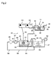
- Figures 1 and 2 are schematic views of a first and second mode of execution.
- an EDM machine 10 is equipped with a first embodiment of the settling device 11.
- This EDM machine includes a work tank 12 in which contains a machining liquid 14 and a workpiece 15 mounted on a table working 16.
- the EDM machine also has an electrode 17 serving as a machining tool mounted on a spindle 18.
- the machining liquid 14 is circulated and thermostatically controlled in the tank working 12 thanks to a stirring installation 20 comprising a circuit pumping 21 with a suction pump 22 and a heat exchanger 23 connected to a cooling water circuit.
- the machining liquid 14 is constituted by a dielectric liquid in which are suspended first particles of an additive intended to facilitate EDM and second contamination particles coming from the electrode and / or the workpiece 15.
- the first particles may for example be graphite particles with a density of 2 to 2.2 gr / cm 3 and a particle size chosen between 1 and 100 ⁇ m, preferably between 1 and 10 ⁇ m.
- the second particles are generally in the form of metal spherules torn off and ejected from the workpiece and from the electrode during erosive discharges. Their density greater than that of the first particles is between 4 and 20 g / cm 3 .
- the particle size of these spherules is generally between 1 and 40 ⁇ m.
- the machining liquid can also comprise third particles in the form of colloidal carbon particles originating from the decomposition of the dielectric liquid under the effect of erosive discharges and which tend to flocculate in clusters submicron.
- the density of these third particles is less than 2 gr / cm 3 and their diameter generally less than 0.5 ⁇ m. It is understood that these third particles do not exist in the case of water as a dielectric liquid.
- the first embodiment of the decantation device 11 has a settling tank 30 for the machining liquid in which a member is placed ultrasonic emission 31 in the form of a sonotrode.
- the latter is connected by a connection 32 to an ultrasonic generator 33 with a frequency of 40 kHz and whose power can be adjusted, for example from 10 to 200 Watts.
- a conduit 34 fitted with a suction pump 35 serves as a means of supplying the liquid contaminated machining in the settling tank 30.
- At least one opening 36 connected to an outlet pipe 37 allows the purified machining liquid to be returned second contamination particles to the EDM machine, i.e. in an additional tank, either directly in the work tank.
- Ultrasound is a very effective way of suspending particles the size of that of the first particles of additive powders.
- the energy of the ultrasound for the suspension of particles must be as much greater than the density of the particles is large and that their size is important. It should be noted that below a critical size, the density a less important than size for diffusion suspension.
- the settling is also slowed down when the viscosity of the working liquid increases. It is therefore possible to produce a selective settling device assisted by moderate energy ultrasound.
- the power of the ultrasonic generator 30 is set for each density and viscosity of the working fluid and each density and size of the particles to be separated. Optimal setting allows decantation and the accumulation on the bottom of the settling tank of the second particles of contamination 38, namely the metal spherules, while keeping in suspends the first 39 lighter particles of the additive, such as graphite.
- the power of this generator 33 is then generally adjusted between 10 and 150 Watts, preferably between 40 and 100 Watts.
- Such a settling device is sufficient for the case of water as dielectric liquid. It can also be used in this form if you accept to leave with the first particles the third particles of carbon from the decomposition of a carbonaceous dielectric liquid, such as oil.
- This second embodiment comprises a first device for sedimentation 11 identical or similar to that described with reference to FIG. 1. It is further equipped with additional means 40 intended to separate the third particles of contamination 41 of the machining liquid which have already been decanted second particles 38.
- additional means include a second decantation device 45, filter elements 46 and a mixing tank 47.
- the second settling device 45 for this purpose comprises a second tank settling tank 50 in which is deposited a second emission member of ultrasound 51, in the form of a second sonotrode connected by a connection 52 to a second ultrasonic generator 53.
- the outlet pipe 37 of the first settling device 11 serves as supply pipe for the machining liquid containing the first and the third particles.
- the second ultrasonic generator 53 has a frequency of 40 kHz and its power can be adjusted for example between 1 and 30 Watts preferably between 5 and 20 Watts. Its power is therefore set lower than that of the first generator 33. It is adjusted to maintain in suspension the third particles 41, while the first particles decant and accumulate on a conveyor belt 55 serving as means of extraction and transport to bring these first particles 39 above the mixing tank 47 where they are discharged.
- An outlet conduit 56 fitted with a pump 57 supplies the machining liquid with the third particles 41 towards the filtration elements 46.
- the latter are arranged to retain all of the third particles 41 and comprise at this effect at least one fine filter, for example a paper cartridge filter.
- the dielectric liquid thus purified 58 is brought through a conduit 59 into the tank mixture 47 where it is mixed with the first particles by organs mixers 60, such as paddles or air circulation, etc.
- the liquid purified and thus reconstituted machining is then renewed by a pipe 61 and a pump 62 to the EDM machine.
Landscapes
- Engineering & Computer Science (AREA)
- Mechanical Engineering (AREA)
- Electrical Discharge Machining, Electrochemical Machining, And Combined Machining (AREA)
- Cleaning By Liquid Or Steam (AREA)
Abstract
Description
Claims (6)
- Dispositif de purification de liquides d'usinage pour machine à électroérosion (10) muni d'une électrode (17) destinée à usiner une pièce (15), le liquide d'usinage (14) étant constitué par un liquide diélectrique contenant au moins des premières particules (39) d'un additif destiné à faciliter l'électroérosion et des secondes particules (38) de contamination provenant de l'électrode (17) et/ou de la pièce (15) et présentant une densité plus élevée que les premières particules (39), caractérisé par le fait que le dispositif comprend au moins un dispositif de décantation à ultrasons (11) comportant un premier bac de décantation (30) pour le liquide d'usinage (14) dans lequel est déposé un premier organe d'émission d'ultrasons (31) relié à un premier générateur d'ultrasons (33) dont la puissance peut être réglée de façon que les secondes particules (38) décantent, tandis que les premières particules (39) restent en suspension dans le liquide diélectrique.
- Dispositif selon la revendication 1, caractérisé par le fait qu'il comprend des moyens d'amenée (34, 35) du liquide d'usinage contaminé dans le premier bac de décantation (30) et au moins une ouverture (36) prévue dans ce dernier pour la sortie du liquide d'usinage purifié contenant les premières particules (39).
- Dispositif selon la revendication 2, caractérisé par le fait qu'il comprend des moyens supplémentaires (40) pour séparer des troisièmes particules (41) de contamination constituées par du carbone colloïdal provenant de la décomposition du liquide d'usinage, ces moyens supplémentaires (40) comportant un second dispositif de décantation à ultrasons (45) avec un second bac de décantation (50) dans lequel est disposé un second organe d'émission d'ultrasons (51) relié à un second générateur d'ultrasons (53), la puissance de ce dernier étant réglée de façon que les premières particules (39) décantent, tandis que les troisièmes particules (41) restent en suspension dans le liquide d'usinage, ce second bac de décantation (50) comportant une entrée reliée à ladite ouverture (36).
- Dispositif selon la revendication 3, caractérisé par le fait que les moyens supplémentaires (40) comportent un bac de mélange (47) avec des organes mélangeurs (60), des éléments de filtration (46) du liquide d'usinage obtenu par décantation à la sortie du second bac de décantation (50) et agencés pour retenir par filtration les troisièmes particules (41), un conduit d'amenée (59) du liquide diélectrique filtré des éléments de filtration (46) audit bac de mélange (47) et des moyens d'extraction et de transport (55) agencés pour transporter les premières particules (39) décantées du second bac de décantation (50) dans le bac de mélange (47).
- Dispositif selon la revendication 4, caractérisé par le fait que lesdits moyens d'extraction et de transport sont constitués par une bande convoyeuse (55) agencée dans le fond du second bac de décantation (50) et menant jusqu'au-dessus du bac de mélange (47) pour décharger les premières particules (39) dans ce dernier.
- Dispositif selon la revendication 3, caractérisé par le fait que le premier générateur d'ultrasons (33) est réglé à une puissance comprise entre 10 et 150 Watts, de préférence entre 40 et 100 Watts et par le fait que le second générateur d'ultrasons (53) est réglé à une puissance plus faible, comprise entre 1 et 30 Watts, de préférence entre 5 et 20 Watts.
Priority Applications (6)
| Application Number | Priority Date | Filing Date | Title |
|---|---|---|---|
| AT00128317T ATE288807T1 (de) | 2000-12-22 | 2000-12-22 | Vorrichtung zur reinigung von bearbeitungsflüssigkeiten in einer funkenerosionsmaschine |
| EP00128317A EP1216778B1 (fr) | 2000-12-22 | 2000-12-22 | Dispositif de purification de liquides d'usinage pour machines à életroérosion |
| ES00128317T ES2234508T3 (es) | 2000-12-22 | 2000-12-22 | Dispositivo de purificacion de liquidos de mecanizado para maquinas de electroerosion. |
| DE60018086T DE60018086T2 (de) | 2000-12-22 | 2000-12-22 | Vorrichtung zur Reinigung von Bearbeitungsflüssigkeiten in einer Funkenerosionsmaschine |
| JP2001382532A JP2002219617A (ja) | 2000-12-22 | 2001-12-17 | 放電加工機械用の加工液体の浄化装置 |
| US10/017,291 US20020079213A1 (en) | 2000-12-22 | 2001-12-18 | Device for the purification of machining liquids for electroerosion machines |
Applications Claiming Priority (1)
| Application Number | Priority Date | Filing Date | Title |
|---|---|---|---|
| EP00128317A EP1216778B1 (fr) | 2000-12-22 | 2000-12-22 | Dispositif de purification de liquides d'usinage pour machines à életroérosion |
Publications (2)
| Publication Number | Publication Date |
|---|---|
| EP1216778A1 true EP1216778A1 (fr) | 2002-06-26 |
| EP1216778B1 EP1216778B1 (fr) | 2005-02-09 |
Family
ID=8170783
Family Applications (1)
| Application Number | Title | Priority Date | Filing Date |
|---|---|---|---|
| EP00128317A Expired - Lifetime EP1216778B1 (fr) | 2000-12-22 | 2000-12-22 | Dispositif de purification de liquides d'usinage pour machines à életroérosion |
Country Status (6)
| Country | Link |
|---|---|
| US (1) | US20020079213A1 (fr) |
| EP (1) | EP1216778B1 (fr) |
| JP (1) | JP2002219617A (fr) |
| AT (1) | ATE288807T1 (fr) |
| DE (1) | DE60018086T2 (fr) |
| ES (1) | ES2234508T3 (fr) |
Families Citing this family (2)
| Publication number | Priority date | Publication date | Assignee | Title |
|---|---|---|---|---|
| US20050218089A1 (en) * | 2004-03-30 | 2005-10-06 | General Electric Company | Flushing and filtering system for electroerosion machining |
| JP5470186B2 (ja) * | 2010-07-30 | 2014-04-16 | 日本発條株式会社 | 被検査物の清浄度検査装置と、清浄度検査方法 |
Citations (4)
| Publication number | Priority date | Publication date | Assignee | Title |
|---|---|---|---|---|
| JPS56119317A (en) * | 1980-02-25 | 1981-09-18 | Inoue Japax Res Inc | Wire cutting electric discharge machining method |
| CH670785A5 (fr) * | 1987-04-03 | 1989-07-14 | Charmilles Technologies | |
| US5298161A (en) * | 1991-01-07 | 1994-03-29 | Erosonic Ag | Apparatus for cleaning the working liquid of an EDM or ECM machine |
| EP0673702A1 (fr) * | 1993-10-08 | 1995-09-27 | Sodick Co., Ltd. | Dispositif et procede d'usinage par etincelage |
Family Cites Families (4)
| Publication number | Priority date | Publication date | Assignee | Title |
|---|---|---|---|---|
| US4523682A (en) * | 1982-05-19 | 1985-06-18 | The United States Of America As Represented By The Administrator Of The National Aeronautics And Space Administration | Acoustic particle separation |
| JPH0679682B2 (ja) * | 1983-10-31 | 1994-10-12 | ブリティッシュ・テクノロジー・グループ・リミテッド | 液体媒質中の粒状物質の分離方法及び装置 |
| SE452116B (sv) * | 1985-09-06 | 1987-11-16 | Hyosong M Lee | Anordning for kontinuerlig separation av fasta partiklar ur en vetskesuspension |
| AT389235B (de) * | 1987-05-19 | 1989-11-10 | Stuckart Wolfgang | Verfahren zur reinigung von fluessigkeiten mittels ultraschall und vorrichtungen zur durchfuehrung dieses verfahrens |
-
2000
- 2000-12-22 EP EP00128317A patent/EP1216778B1/fr not_active Expired - Lifetime
- 2000-12-22 DE DE60018086T patent/DE60018086T2/de not_active Expired - Lifetime
- 2000-12-22 AT AT00128317T patent/ATE288807T1/de not_active IP Right Cessation
- 2000-12-22 ES ES00128317T patent/ES2234508T3/es not_active Expired - Lifetime
-
2001
- 2001-12-17 JP JP2001382532A patent/JP2002219617A/ja active Pending
- 2001-12-18 US US10/017,291 patent/US20020079213A1/en not_active Abandoned
Patent Citations (4)
| Publication number | Priority date | Publication date | Assignee | Title |
|---|---|---|---|---|
| JPS56119317A (en) * | 1980-02-25 | 1981-09-18 | Inoue Japax Res Inc | Wire cutting electric discharge machining method |
| CH670785A5 (fr) * | 1987-04-03 | 1989-07-14 | Charmilles Technologies | |
| US5298161A (en) * | 1991-01-07 | 1994-03-29 | Erosonic Ag | Apparatus for cleaning the working liquid of an EDM or ECM machine |
| EP0673702A1 (fr) * | 1993-10-08 | 1995-09-27 | Sodick Co., Ltd. | Dispositif et procede d'usinage par etincelage |
Non-Patent Citations (1)
| Title |
|---|
| PATENT ABSTRACTS OF JAPAN vol. 005, no. 203 (M - 103) 23 December 1981 (1981-12-23) * |
Also Published As
| Publication number | Publication date |
|---|---|
| EP1216778B1 (fr) | 2005-02-09 |
| DE60018086T2 (de) | 2006-02-23 |
| ES2234508T3 (es) | 2005-07-01 |
| JP2002219617A (ja) | 2002-08-06 |
| DE60018086D1 (de) | 2005-03-17 |
| ATE288807T1 (de) | 2005-02-15 |
| US20020079213A1 (en) | 2002-06-27 |
Similar Documents
| Publication | Publication Date | Title |
|---|---|---|
| TW544336B (en) | Preparation of high performance silica slurry using a centrifuge | |
| US8056551B2 (en) | Method and system for manufacturing wafer-like slices from a substrate material | |
| US8940174B2 (en) | Method for treating spent abrasive slurry | |
| JPWO2008020507A1 (ja) | 研磨剤スラリー廃液からの研磨剤回収方法及び装置 | |
| CN101681808B (zh) | 从半导体晶片制造工艺再生废浆料的再生工艺和再生系统 | |
| WO2001040121A1 (fr) | Procede et installation de clarification des liquides et suspensions par floculation lestee et decantation | |
| FR2922123A1 (fr) | Installation pour la floculation de boues chargees de matieres en suspension, procede mettant en oeuvre l'installation | |
| WO2000029335A1 (fr) | Procede de traitement d'eau par flocs lestes integrant un recyclage de materiau granulaire | |
| KR100393007B1 (ko) | 반도체 웨이퍼 제조공정에서 발생하는 폐슬러리 재생방법및 그 재생시스템 | |
| EP1216778B1 (fr) | Dispositif de purification de liquides d'usinage pour machines à életroérosion | |
| JP3816200B2 (ja) | 微細粒子を含む液体の処理方法および処理装置 | |
| EP0121511A1 (fr) | Appareil mobile de nettoyage par aspiration | |
| CN104812532B (zh) | 冷却剂再生方法以及冷却剂再生装置 | |
| CN209061399U (zh) | 一种管式离心机 | |
| JP2011083845A (ja) | 研磨用固液回収分離装置 | |
| CA2376795C (fr) | Procede et appareil pour la preparation de pate a papier a partir de vieux papiers | |
| JPH11253838A (ja) | シリコンウエハー製造工程における微粒混合液体の固液分離方法及び装置 | |
| EP0556362B1 (fr) | Procede et dispositif pour la filtration d'un liquide contenant des particules en suspension | |
| KR100385177B1 (ko) | 와이어 소우 절단용 폐 절단액 재생방법 | |
| JPH10230188A (ja) | 工作機械用切削油剤浄化装置 | |
| JP2013237130A (ja) | クーラントを回収する方法 | |
| CH692138A5 (fr) | Installation de tranchage avec dispositif de traitement de la barbotine. | |
| JP3505710B2 (ja) | クーラント清浄装置 | |
| WO2009044074A2 (fr) | Procede de separation solide/liquide d'effluent et separateur pour sa mise en oeuvre | |
| TWI546160B (zh) | 冷卻劑再生方法 |
Legal Events
| Date | Code | Title | Description |
|---|---|---|---|
| PUAI | Public reference made under article 153(3) epc to a published international application that has entered the european phase |
Free format text: ORIGINAL CODE: 0009012 |
|
| AK | Designated contracting states |
Kind code of ref document: A1 Designated state(s): AT BE CH CY DE DK ES FI FR GB GR IE IT LI LU MC NL PT SE TR |
|
| AX | Request for extension of the european patent |
Free format text: AL;LT;LV;MK;RO;SI |
|
| 17P | Request for examination filed |
Effective date: 20020720 |
|
| AKX | Designation fees paid |
Designated state(s): AT BE CH CY DE DK ES FI FR GB GR IE IT LI LU MC NL PT SE TR |
|
| GRAP | Despatch of communication of intention to grant a patent |
Free format text: ORIGINAL CODE: EPIDOSNIGR1 |
|
| GRAS | Grant fee paid |
Free format text: ORIGINAL CODE: EPIDOSNIGR3 |
|
| GRAA | (expected) grant |
Free format text: ORIGINAL CODE: 0009210 |
|
| AK | Designated contracting states |
Kind code of ref document: B1 Designated state(s): AT BE CH CY DE DK ES FI FR GB GR IE IT LI LU MC NL PT SE TR |
|
| PG25 | Lapsed in a contracting state [announced via postgrant information from national office to epo] |
Ref country code: IT Free format text: LAPSE BECAUSE OF FAILURE TO SUBMIT A TRANSLATION OF THE DESCRIPTION OR TO PAY THE FEE WITHIN THE PRESCRIBED TIME-LIMIT;WARNING: LAPSES OF ITALIAN PATENTS WITH EFFECTIVE DATE BEFORE 2007 MAY HAVE OCCURRED AT ANY TIME BEFORE 2007. THE CORRECT EFFECTIVE DATE MAY BE DIFFERENT FROM THE ONE RECORDED. Effective date: 20050209 Ref country code: GB Free format text: LAPSE BECAUSE OF FAILURE TO SUBMIT A TRANSLATION OF THE DESCRIPTION OR TO PAY THE FEE WITHIN THE PRESCRIBED TIME-LIMIT Effective date: 20050209 Ref country code: FI Free format text: LAPSE BECAUSE OF FAILURE TO SUBMIT A TRANSLATION OF THE DESCRIPTION OR TO PAY THE FEE WITHIN THE PRESCRIBED TIME-LIMIT Effective date: 20050209 Ref country code: NL Free format text: LAPSE BECAUSE OF FAILURE TO SUBMIT A TRANSLATION OF THE DESCRIPTION OR TO PAY THE FEE WITHIN THE PRESCRIBED TIME-LIMIT Effective date: 20050209 Ref country code: IE Free format text: LAPSE BECAUSE OF FAILURE TO SUBMIT A TRANSLATION OF THE DESCRIPTION OR TO PAY THE FEE WITHIN THE PRESCRIBED TIME-LIMIT Effective date: 20050209 Ref country code: AT Free format text: LAPSE BECAUSE OF FAILURE TO SUBMIT A TRANSLATION OF THE DESCRIPTION OR TO PAY THE FEE WITHIN THE PRESCRIBED TIME-LIMIT Effective date: 20050209 Ref country code: TR Free format text: LAPSE BECAUSE OF FAILURE TO SUBMIT A TRANSLATION OF THE DESCRIPTION OR TO PAY THE FEE WITHIN THE PRESCRIBED TIME-LIMIT Effective date: 20050209 |
|
| REG | Reference to a national code |
Ref country code: GB Ref legal event code: FG4D Free format text: NOT ENGLISH |
|
| REG | Reference to a national code |
Ref country code: CH Ref legal event code: EP |
|
| REG | Reference to a national code |
Ref country code: IE Ref legal event code: FG4D Free format text: FRENCH |
|
| REG | Reference to a national code |
Ref country code: CH Ref legal event code: NV Representative=s name: GEORG FISCHER AG |
|
| REF | Corresponds to: |
Ref document number: 60018086 Country of ref document: DE Date of ref document: 20050317 Kind code of ref document: P |
|
| PG25 | Lapsed in a contracting state [announced via postgrant information from national office to epo] |
Ref country code: DK Free format text: LAPSE BECAUSE OF FAILURE TO SUBMIT A TRANSLATION OF THE DESCRIPTION OR TO PAY THE FEE WITHIN THE PRESCRIBED TIME-LIMIT Effective date: 20050509 Ref country code: GR Free format text: LAPSE BECAUSE OF FAILURE TO SUBMIT A TRANSLATION OF THE DESCRIPTION OR TO PAY THE FEE WITHIN THE PRESCRIBED TIME-LIMIT Effective date: 20050509 Ref country code: SE Free format text: LAPSE BECAUSE OF FAILURE TO SUBMIT A TRANSLATION OF THE DESCRIPTION OR TO PAY THE FEE WITHIN THE PRESCRIBED TIME-LIMIT Effective date: 20050509 |
|
| REG | Reference to a national code |
Ref country code: ES Ref legal event code: FG2A Ref document number: 2234508 Country of ref document: ES Kind code of ref document: T3 |
|
| NLV1 | Nl: lapsed or annulled due to failure to fulfill the requirements of art. 29p and 29m of the patents act | ||
| GBV | Gb: ep patent (uk) treated as always having been void in accordance with gb section 77(7)/1977 [no translation filed] |
Effective date: 20050209 |
|
| REG | Reference to a national code |
Ref country code: IE Ref legal event code: FD4D |
|
| PLBE | No opposition filed within time limit |
Free format text: ORIGINAL CODE: 0009261 |
|
| STAA | Information on the status of an ep patent application or granted ep patent |
Free format text: STATUS: NO OPPOSITION FILED WITHIN TIME LIMIT |
|
| PG25 | Lapsed in a contracting state [announced via postgrant information from national office to epo] |
Ref country code: CY Free format text: LAPSE BECAUSE OF FAILURE TO SUBMIT A TRANSLATION OF THE DESCRIPTION OR TO PAY THE FEE WITHIN THE PRESCRIBED TIME-LIMIT Effective date: 20051222 |
|
| PG25 | Lapsed in a contracting state [announced via postgrant information from national office to epo] |
Ref country code: MC Free format text: LAPSE BECAUSE OF NON-PAYMENT OF DUE FEES Effective date: 20051231 Ref country code: BE Free format text: LAPSE BECAUSE OF NON-PAYMENT OF DUE FEES Effective date: 20051231 Ref country code: LU Free format text: LAPSE BECAUSE OF NON-PAYMENT OF DUE FEES Effective date: 20051231 |
|
| 26N | No opposition filed |
Effective date: 20051110 |
|
| BERE | Be: lapsed |
Owner name: CHARMILLES TECHNOLOGIES S.A. Effective date: 20051231 |
|
| PG25 | Lapsed in a contracting state [announced via postgrant information from national office to epo] |
Ref country code: PT Free format text: LAPSE BECAUSE OF NON-PAYMENT OF DUE FEES Effective date: 20050709 |
|
| PGFP | Annual fee paid to national office [announced via postgrant information from national office to epo] |
Ref country code: FR Payment date: 20110104 Year of fee payment: 11 |
|
| PGFP | Annual fee paid to national office [announced via postgrant information from national office to epo] |
Ref country code: CH Payment date: 20101224 Year of fee payment: 11 |
|
| PGFP | Annual fee paid to national office [announced via postgrant information from national office to epo] |
Ref country code: DE Payment date: 20101222 Year of fee payment: 11 |
|
| PGFP | Annual fee paid to national office [announced via postgrant information from national office to epo] |
Ref country code: ES Payment date: 20101223 Year of fee payment: 11 |
|
| REG | Reference to a national code |
Ref country code: CH Ref legal event code: PUE Owner name: AGIE CHARMILLES SA Free format text: CHARMILLES TECHNOLOGIES S.A.#8-10, RUE DU PRE-DE-LA-FONTAINE CASE POSTALE 373#1217 MEYRIN 1 (CH) -TRANSFER TO- AGIE CHARMILLES SA#VIA DEI PIOPPI 2#6616 LOSONE (CH) |
|
| REG | Reference to a national code |
Ref country code: CH Ref legal event code: PL |
|
| REG | Reference to a national code |
Ref country code: FR Ref legal event code: ST Effective date: 20120831 |
|
| REG | Reference to a national code |
Ref country code: DE Ref legal event code: R119 Ref document number: 60018086 Country of ref document: DE Effective date: 20120703 |
|
| PG25 | Lapsed in a contracting state [announced via postgrant information from national office to epo] |
Ref country code: DE Free format text: LAPSE BECAUSE OF NON-PAYMENT OF DUE FEES Effective date: 20120703 Ref country code: CH Free format text: LAPSE BECAUSE OF NON-PAYMENT OF DUE FEES Effective date: 20111231 Ref country code: LI Free format text: LAPSE BECAUSE OF NON-PAYMENT OF DUE FEES Effective date: 20111231 |
|
| PG25 | Lapsed in a contracting state [announced via postgrant information from national office to epo] |
Ref country code: FR Free format text: LAPSE BECAUSE OF NON-PAYMENT OF DUE FEES Effective date: 20120102 |
|
| REG | Reference to a national code |
Ref country code: ES Ref legal event code: FD2A Effective date: 20130703 |
|
| PG25 | Lapsed in a contracting state [announced via postgrant information from national office to epo] |
Ref country code: ES Free format text: LAPSE BECAUSE OF NON-PAYMENT OF DUE FEES Effective date: 20111223 |