EP0673702A1 - Dispositif et procede d'usinage par etincelage - Google Patents
Dispositif et procede d'usinage par etincelage Download PDFInfo
- Publication number
- EP0673702A1 EP0673702A1 EP94929020A EP94929020A EP0673702A1 EP 0673702 A1 EP0673702 A1 EP 0673702A1 EP 94929020 A EP94929020 A EP 94929020A EP 94929020 A EP94929020 A EP 94929020A EP 0673702 A1 EP0673702 A1 EP 0673702A1
- Authority
- EP
- European Patent Office
- Prior art keywords
- electric discharge
- workpiece
- fluid
- machining
- work tank
- Prior art date
- Legal status (The legal status is an assumption and is not a legal conclusion. Google has not performed a legal analysis and makes no representation as to the accuracy of the status listed.)
- Granted
Links
- 238000003754 machining Methods 0.000 title claims abstract description 53
- 238000000034 method Methods 0.000 title claims description 9
- 239000012530 fluid Substances 0.000 claims description 71
- 238000001179 sorption measurement Methods 0.000 claims description 25
- 239000012254 powdered material Substances 0.000 claims description 13
- 239000000843 powder Substances 0.000 abstract description 11
- 239000000463 material Substances 0.000 abstract description 4
- 239000000696 magnetic material Substances 0.000 abstract description 3
- 230000006698 induction Effects 0.000 abstract 2
- 239000007788 liquid Substances 0.000 abstract 2
- 230000000149 penetrating effect Effects 0.000 abstract 1
- 238000013019 agitation Methods 0.000 description 3
- 230000003746 surface roughness Effects 0.000 description 3
- 238000010276 construction Methods 0.000 description 2
- OKTJSMMVPCPJKN-UHFFFAOYSA-N Carbon Chemical compound [C] OKTJSMMVPCPJKN-UHFFFAOYSA-N 0.000 description 1
- 229910000976 Electrical steel Inorganic materials 0.000 description 1
- XUIMIQQOPSSXEZ-UHFFFAOYSA-N Silicon Chemical compound [Si] XUIMIQQOPSSXEZ-UHFFFAOYSA-N 0.000 description 1
- 229910000831 Steel Inorganic materials 0.000 description 1
- XAGFODPZIPBFFR-UHFFFAOYSA-N aluminium Chemical compound [Al] XAGFODPZIPBFFR-UHFFFAOYSA-N 0.000 description 1
- 229910052782 aluminium Inorganic materials 0.000 description 1
- 239000004020 conductor Substances 0.000 description 1
- 238000010586 diagram Methods 0.000 description 1
- 230000000694 effects Effects 0.000 description 1
- 238000005516 engineering process Methods 0.000 description 1
- 239000010439 graphite Substances 0.000 description 1
- 229910002804 graphite Inorganic materials 0.000 description 1
- 229910052809 inorganic oxide Inorganic materials 0.000 description 1
- 239000003350 kerosene Substances 0.000 description 1
- 239000002480 mineral oil Substances 0.000 description 1
- 235000010446 mineral oil Nutrition 0.000 description 1
- 239000003921 oil Substances 0.000 description 1
- 239000002245 particle Substances 0.000 description 1
- 229920001296 polysiloxane Polymers 0.000 description 1
- 238000005086 pumping Methods 0.000 description 1
- 239000011347 resin Substances 0.000 description 1
- 229920005989 resin Polymers 0.000 description 1
- 239000004065 semiconductor Substances 0.000 description 1
- 229910052710 silicon Inorganic materials 0.000 description 1
- 239000010703 silicon Substances 0.000 description 1
- 229910001220 stainless steel Inorganic materials 0.000 description 1
- 239000010935 stainless steel Substances 0.000 description 1
- 239000010959 steel Substances 0.000 description 1
- 239000002699 waste material Substances 0.000 description 1
Images


Classifications
-
- B—PERFORMING OPERATIONS; TRANSPORTING
- B23—MACHINE TOOLS; METAL-WORKING NOT OTHERWISE PROVIDED FOR
- B23H—WORKING OF METAL BY THE ACTION OF A HIGH CONCENTRATION OF ELECTRIC CURRENT ON A WORKPIECE USING AN ELECTRODE WHICH TAKES THE PLACE OF A TOOL; SUCH WORKING COMBINED WITH OTHER FORMS OF WORKING OF METAL
- B23H1/00—Electrical discharge machining, i.e. removing metal with a series of rapidly recurring electrical discharges between an electrode and a workpiece in the presence of a fluid dielectric
- B23H1/10—Supply or regeneration of working media
Definitions
- the present invention relates to an electric discharge machine and method which uses a tool electrode to perform electric discharge machining on a workpiece. More specifically, the present invention relates to an electric discharge machine and method which use a machining fluid in which a powder is mixed into an oil-based dielectric fluid.
- electric discharge machines include a work tank which contains the workpiece, a fluid supply device which supplies a dielectric fluid such as kerosene to the work tank, and a power supply which supplies power to the space between the tool electrode and the workpiece known as the "gap.”
- Electric discharge machining occurs at the gap, in work tank which is filled with the dielectric fluid.
- a powder material composed of a semiconductor such as polycrystal silicon, or a good electric conductor such as aluminum or graphite, or an inorganic oxide or inorganic carbide, with a particle diameter of between 1 ⁇ m and 50 ⁇ m, is mixed into the dielectric fluid.
- a fluid supply device which can, in accordance with the intended purpose of machining, selectively supply either powder-bearing fluid or non-powder-bearing fluid.
- Such electric discharge machines generally also require two additional devices.
- a device which separates machining waste produced by electric discharge machining from the powder-bearing fluid.
- a large specific-gravity centrifugal separator may be provided for this purpose.
- a device containing a magnetic material is provided in an appropriate part of the fluid supply device, such as the fluid reservoir tank or fluid circulation path.
- a device which prevents settling of the powdered material.
- an agitator is provided in the work tank to agitate the fluid.
- the agitator prevents the settling of powdered material by agitating the fluid in the work tank, but at the same time it inhibits the settling of machining chips produced by the machining process.
- the agitator can also cause machining chips which had settled to become re-suspended in the fluid. As a result, the machining chips suspended in the fluid can enter the machining area, where it will have undesirable effects on the electric discharge machining process.
- the purpose of the present invention is to provide an electric discharge machine and method which reliably removes machining chips suspended in the fluid by the agitator.
- an electric discharge machine which machines a workpiece by generating an electric discharge across a gap formed between a workpiece and a tool electrode, both of which are positioned in a work tank filled with a dielectric fluid into which a powdered material is mixed.
- the electric discharge machine includes an agitator, which agitates the dielectric fluid and prevents the settling of powdered material in the fluid, and a magnetic adsorption device, which is positioned in the work tank and which adsorbs machining chips produced by the electric discharge machining process.
- the magnetic adsorption device will preferably be positioned so that it faces the flow of dielectric fluid produced by the agitator in the work tank.
- the magnetic adsorption device may also be positioned so that it surrounds the workpiece about its sides. It is preferable that the magnetic adsorption device include multiple magnetic pieces and retainers which maintain a parallel interval between those magnetic pieces. It is also preferable that the multiple magnetic pieces be formed in a cylindrical or flat shape.
- an electric discharge machining method which uses an electric discharge machine for machining a workpiece positioned in a work tank filled with dielectric fluid by electric discharges using a tool electrode, includes a step in which the dielectric fluid is agitated in order to prevent settling of the powdered material, a step in which the workpiece is machined by generating electric discharges in the gap formed between the workpiece and the tool electrode, and a step in which the machining chips produced by the electric discharges is adsorbed using magnetic bodies.
- FIG. 1 is an overview diagram illustrating an exemplary embodiment of an electric discharge machine according to the present invention.
- FIG. 2 is an external view illustrating another example of a machining chip adsorption device.
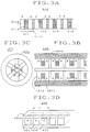
- FIG. 3A is a section depicting an example of the magnetic pieces in a machining chip adsorption device.
- FIGS. 3B and 3C are sections depicting another example of the magnetic pieces in a machining chip adsorption device.
- FIG. 3D is an external view depicting still another example of the magnetic pieces in a machining chip adsorption device.
- FIG. 1 is an overview drawing illustrating an embodiment of the electric discharge machine according to the present invention.
- the electric discharge machine includes a bed 7 and an XY cross-table 4 attached to the bed.
- Work tank 3 is fastened to the XY cross-table 4 in such a way that it can be filled with fluid.
- a column 6 stands upright on the bed 7, and is positioned behind the work tank 3.
- a servo-head 5 is attached to the column 6.
- a tool electrode 1 is fastened to the servo-head 5 by an appropriate electrode holder and faces the workpiece 2, which is affixed to the XY cross-table 4.
- the servo-head 5, includes a Z-axis motor, moves the tool electrode 1 in a direction perpendicular to the XY cross table 4.
- the electric discharge machine further includes a combination power supply/control unit 10 which supplies power to the gap formed between the tool electrode 1 and the workpiece 2.
- a control unit 10 controls the X-axis motor and Y-axis motor (not shown) which drive the XY cross-table 4 and cause the workpiece 2 to move relative to the tool electrode 1 in the horizontal plane.
- the control unit 10 also controls the Z-axis motor.
- the electric discharge machine further includes a fluid supply unit 20, which supplies a mineral oil-based machining fluid to the work tank 3 through a flexible tube 8.
- a flexible tube 9 is provided which discharges the fluid from the work tank 3 to the fluid supply unit 20.
- the fluid supply unit 20 includes a fluid supply section 21, which stores non-powder-bearing dielectric fluid F1 and supplies the fluid F1 to the work tank 3, and a supply section 22, which stores powder-bearing dielectric fluid F2 and supplies the fluid F2 to the work tank 3.
- the fluid supply unit 20 also includes a switch 23 which selectively supplies the fluids F1 or F2 to the work tank 3 and selectively returns fluid discharged from the work tank 3 to the fluid supply units 21 or 22. The switch 23 is controlled by a signal from the control unit 10.
- An agitator 30 is provided in order to prevent the settling of the powdered material.
- the agitator 30 includes a drive motor and an agitation blade attached to the end of the driveshaft thereof.
- the agitator 30 may, for example, be attached to the side wall of the work tank 3 using an appropriate fastener.
- the agitation blade is formed in a propeller shape, and is positioned within the fluid-filled tank.
- a drive source 31 is connected to the drive motor and is activated in response to a signal from the control unit 10.
- An appropriate number of additional agitators may also be erected in order to reliably prevent the powdered material from settling.
- a machining chip adsorption device 40 which contains, for example, multiple magnetic pieces such as permanent magnets or electromagnets, is also provided in order to separate the machining chips produced by electric discharge machining. These magnetic pieces may be formed as cylinders having a diameter of approximately 1-2 cm, and there are multiple magnetic poles on the perimeter surface thereof.
- the adsorption device 40 also has retainers which suspend the magnetic pieces from their top ends in such a way that the multiple magnetic pieces are arrayed in a line perpendicular to and at an interval from the XY cross table 4 and parallel to one another.
- the magnetic pieces in a row are suspended in the work tank 3 in such a way as to cross the fluid flow stream produced by the agitator 30 and in a such a way that the bottom ends of the magnetic pieces virtually reach the bottom of work tank 3.
- a controller 44 is provided to energize and denergize the electromagnets.
- FIG. 2 is an top view of work tank 3. It illustrates an embodiment of an electric discharge machine provided with multiple adsorption devices.
- plural machining chip adsorption devices 401, 402, 403, and 404 are positioned on the XY cross table 4 in the work tank 3 in such a way as to surround the workpiece 2 about its sides. Parts identical to those shown in FIG. 1 are assigned the same reference numerals, and an explanation thereof is omitted.
- the adsorption device 401 includes multiple cylindrical electromagnets 401a, which are of sufficient length that they virtually reach from the bottom of work tank 3 to the fluid surface, and retainers 401b, which hold the lower ends of the electromagnets 401a and are arrayed on the XY cross table 4.
- the magnetic pieces 401a are, for example, electromagnets with cores formed of laminated silicone steel plate.
- the electromagnets 401a are held parallel to one another and perpendicular to and at an interval with respect to the XY cross table 4.
- Electromagnets 401a may, as with the adsorption device 40 shown in FIG 1, be suspended using appropriate retainers to hold the top ends thereof.
- the electromagnets 401a may also be arrayed parallel to one another and parallel to and at an interval with respect to the XY cross table 4 using cable or wire so as to form a folding curtain.
- multiple magnetic pieces 401a will be arrayed so that a magnetic field is generated parallel to the axes of the magnetic pieces and, further, so as to form some degree of magnetic field between the magnetic pieces themselves.
- the other adsorption devices 402, 403, and 404 are typically of the same construction as the adsorption device 401.
- FIGS. 3A, 3B, 3C, and 3D are section drawings depicting examples of the magnetic pieces of a machining chip adsorption device.
- the magnetic piece 410 illustrated in FIG. 3A has multiple electromagnets 411, 412, 413, and 414 connected by a non-magnetic body.
- the electromagnet 411 includes a rotating I-shaped core 411a, a coil 411b wound around the trunk of the core 411a, and a non-magnetic body 411c.
- a magnetic field is formed at both ends of rotating I-shaped core 411a, and also between the opposite poles of an electromagnet 412 which, interposed by a non-magnetic body, adjoins it.
- the core 411a may also be formed in a hollow cylindrical tube shape, with rod-shaped permanent magnets inserted into the hollow portion thereof.
- the hollow gap around the core 411a will be filled with a non-magnetic body such as plastic rather than with the coil 411b.
- a cylindrical part formed of thin stainless steel or plastic is fashioned, into which magnetic piece 410 is inserted. Machining chips adsorbed on the outer surface of the cylindrical part can be easily peeled off when magnetic piece 410 is extracted from this cylindrical part.
- the elongated cylindrical magnetic piece 420 illustrated in FIGS. 3B and 3C includes a cylindrical piece 420a comprising a non-magnetic body.
- the magnetic piece 420 further includes plural cores 421a, each comprising a squared-off "C"-shaped silicon steel plate laminate -- in the example illustrated, 6 such cores 421a are radially arrayed in 60 degree divisions around the axis of the cylindrical piece 420a as depicted in FIG 3C.
- a coil 421b is wound around each of the plurality of 6 cores 421a to form an approximately disk-shaped electromagnet in which the lines of magnetic force extend radially.
- electromagnets may be stacked up along the aforementioned axis to constitute an elongated rod shape, and an appropriate non-magnetic body may be used to fill the spaces between the cores 421a and the electromagnets and inserted into the cylindrical piece 420a.
- a permanent magnet constitution may be adopted in which permanent cylindrical magnets are inserted coaxially into the bottom of the 6 cores in place of the coil 421b.
- multiple permanent magnets 431, 432, 433, etc. are positioned within a casing piece 430a in such a way that magnetic poles are generated on the side walls of the elongated rod-shaped body.
- This assembly is inserted into a thin-walled container, and removal of adsorbed machining chips is accomplished by extracting the magnet 430 from the aforementioned container.
- a columnar shape using electromagnets was adopted in the embodiment of FIG. 2, but as shown in FIG 3D, the device may also be formed as an elongated square pillar, plate, or columnar shape, using multiple small permanent magnets internally and covering them with resin, etc.
- fluid F1 is supplied to the work tank 3 in accordance with a command signal from the control unit 10, and the workpiece 2 is submerged in the fluid F1.
- a course removal operation is then performed on the workpiece 2 under the requisite machining conditions. Multiple machining conditions may be sequentially changed as required to gradually finish the workpiece to the requisite machining dimensions and machining surface roughness.
- the fluid F1 is supplied constantly from the fluid supply section 21 to the work tank 3; the fluid F1 in the work tank 3 overflows, forming a relatively slow machining fluid flow which returns to the fluid supply section 21.
- the fluid F1 By jetting the fluid F1 into or suctioning it from the gap through the path formed in the tool electrode 1 or the workpiece 2, machining chips produced at the gap formed between the tool electrode 1 and the workpiece 2 as a result of electric discharge machining are removed.
- the fluid F1 can also be jetted into the gap using a flexible hose equipped with a nozzle.
- Electrode 1 is cyclically moved a specified distance in a direction away from the workpiece 2 and then immediately moved back into proximity with the workpiece 2.
- the work piece 2 Upon completion of the rough machining process, the work piece 2 is finished using the fluid F2.
- the fluid F1 is discharged from the work tank 3 to the fluid supply section 21 through the tube 9.
- the fluid F2 is supplied from the fluid supply section 22 to the work tank 3 through the tube 8, and the workpiece 2 is submerged in the fluid F2.
- a signal is sent from a fluid surface detector (not shown) to the control unit 10.
- the control unit 10 drives the agitator 30 while at the same time turning on the power supply in controller 44, so that a magnetic field is generated on the surface magnetic pole portion of adsorption device 40 and an adsorbing magnetic field is formed.
- the agitator 30 agitates the fluid F2 in the work tank 3, the machining chips which had settled as residue in the work tank 3 are churned up by the agitation-induced fluid flow, and become suspended in the fluid in the work tank 3 along with the powdered material.
- the workpiece 2 can be machined under requisite machining conditions in such a way that required dimensional accuracies and surface roughness are achieved.
- the adsorption device 40 should preferably be activated during the finishing processing so as to remove machining chips suspended in the fluid F2.
Landscapes
- Engineering & Computer Science (AREA)
- Mechanical Engineering (AREA)
- Electrical Discharge Machining, Electrochemical Machining, And Combined Machining (AREA)
Applications Claiming Priority (3)
| Application Number | Priority Date | Filing Date | Title |
|---|---|---|---|
| JP285484/93 | 1993-10-08 | ||
| JP5285484A JPH07108419A (ja) | 1993-10-08 | 1993-10-08 | 放電加工装置及びこの装置を用いる放電加工方法 |
| PCT/JP1994/001685 WO1995010383A1 (fr) | 1993-10-08 | 1994-10-07 | Dispositif et procede d'usinage par etincelage |
Publications (3)
| Publication Number | Publication Date |
|---|---|
| EP0673702A1 true EP0673702A1 (fr) | 1995-09-27 |
| EP0673702A4 EP0673702A4 (fr) | 1996-02-14 |
| EP0673702B1 EP0673702B1 (fr) | 1998-06-10 |
Family
ID=17692121
Family Applications (1)
| Application Number | Title | Priority Date | Filing Date |
|---|---|---|---|
| EP94929020A Expired - Lifetime EP0673702B1 (fr) | 1993-10-08 | 1994-10-07 | Dispositif et procede d'usinage par etincelage |
Country Status (5)
| Country | Link |
|---|---|
| US (1) | US5767473A (fr) |
| EP (1) | EP0673702B1 (fr) |
| JP (1) | JPH07108419A (fr) |
| DE (1) | DE69410981D1 (fr) |
| WO (1) | WO1995010383A1 (fr) |
Cited By (4)
| Publication number | Priority date | Publication date | Assignee | Title |
|---|---|---|---|---|
| EP1216778A1 (fr) * | 2000-12-22 | 2002-06-26 | Charmilles Technologies S.A. | Dispositif de purification de liquides d'usinage pour machines à életroérosion |
| CN1101291C (zh) * | 1995-10-13 | 2003-02-12 | 三菱电机株式会社 | 放电加工装置的加工液处理装置 |
| EP1238739A3 (fr) * | 2001-03-09 | 2005-02-09 | Fanuc Ltd | Machine pour usinage par électoérosion par fil |
| CN113708592A (zh) * | 2021-08-19 | 2021-11-26 | 中国科学院宁波材料技术与工程研究所 | 永磁自悬浮式磁性液体动能采集器 |
Families Citing this family (9)
| Publication number | Priority date | Publication date | Assignee | Title |
|---|---|---|---|---|
| JP2003039243A (ja) * | 2001-08-02 | 2003-02-12 | Mitsubishi Electric Corp | 放電加工方法及び装置 |
| CN102554375B (zh) * | 2012-01-17 | 2014-06-18 | 群基精密工业(苏州)有限公司 | 一种具有液位调整装置的放电加工机油槽 |
| CN102950344B (zh) * | 2012-11-07 | 2014-08-13 | 南京航空航天大学 | 纳米磁性粒子改善微细电解线切割产物排出方法 |
| RU2621325C2 (ru) * | 2014-11-11 | 2017-06-02 | Федеральное государственное бюджетное образовательное учреждение высшего профессионального образования "Воронежский государственный технический университет" | Способ подготовки прокачиваемой через зону обработки при электрохимической размерной обработке рабочей среды и устройство для его осуществления |
| CN106825798B (zh) * | 2017-01-06 | 2018-08-07 | 宁波工程学院 | 电火花液雾化喷头 |
| CN106695031B (zh) * | 2017-01-06 | 2018-06-29 | 宁波工程学院 | 一种电火花液雾化喷头 |
| CN106825806B (zh) * | 2017-03-29 | 2019-04-30 | 江苏大学 | 一种磁场引导电解电火花复合加工弯孔的装置及方法 |
| KR102377604B1 (ko) * | 2021-12-23 | 2022-03-23 | 주식회사 메인텍 | 방전가공 아크방지 지그 장치 |
| KR102404433B1 (ko) * | 2021-12-29 | 2022-06-02 | 주식회사 메인텍 | 방전가공 아크방지 지그 장치 |
Family Cites Families (17)
| Publication number | Priority date | Publication date | Assignee | Title |
|---|---|---|---|---|
| US3477948A (en) * | 1965-12-13 | 1969-11-11 | Inoue K | Magnetic filter and method of operating same |
| US4408113A (en) * | 1978-03-02 | 1983-10-04 | Inoue-Japax Research Incorporated | Electrical machining apparatus |
| US4392042A (en) * | 1980-02-25 | 1983-07-05 | Inoue-Japax Research Incorporated | Method of and apparatus for electroerosively wire-cutting a conductive workpiece |
| US4387286A (en) * | 1980-03-26 | 1983-06-07 | Inoue-Japax Research Incorporated | Apparatus for controlling splashes and purification of a machining liquid |
| JPS591124A (ja) * | 1982-06-23 | 1984-01-06 | Inoue Japax Res Inc | 放電加工装置 |
| DE98711T1 (de) * | 1982-06-23 | 1985-01-31 | Inoue-Japax Research Inc., Yokohama, Kanagawa | Elektrisches bearbeitungssystem und verfahren zur behandlung einer bearbeitungsfluessigkeit im system. |
| JPS61219533A (ja) * | 1985-03-26 | 1986-09-29 | Mitsubishi Electric Corp | ワイヤ放電加工装置 |
| DE3530536A1 (de) * | 1985-08-27 | 1987-03-05 | Emil Freiwald | Magnetfeld-ansauggeraet asf 140/60/12 |
| JPS62259717A (ja) * | 1986-05-01 | 1987-11-12 | Ibuki Denshi Seiki:Kk | ワイヤカツト放電加工用の加工廃液浄化方法及び装置 |
| CH670785A5 (fr) * | 1987-04-03 | 1989-07-14 | Charmilles Technologies | |
| JPH01140925A (ja) * | 1987-11-25 | 1989-06-02 | Fujikura Ltd | 放電加工液の加工屑除去方法 |
| JP2932503B2 (ja) * | 1989-03-23 | 1999-08-09 | 株式会社リコー | 電子写真感光体 |
| JPH0823333B2 (ja) * | 1989-06-12 | 1996-03-06 | 株式会社日立製作所 | 内燃機関の点火時期制御装置 |
| JPH0733882Y2 (ja) * | 1989-06-12 | 1995-08-02 | 東急車輌製造株式会社 | 磁気吸着式スラツジ分離装置 |
| JPH0733880Y2 (ja) * | 1989-06-26 | 1995-08-02 | 東急車輌製造株式会社 | クーラント清浄装置用スラッジ分離筒 |
| JP2590633B2 (ja) * | 1990-11-30 | 1997-03-12 | 三菱電機株式会社 | 放電加工装置 |
| JP3002288B2 (ja) * | 1991-04-13 | 2000-01-24 | 株式会社ソディック | 放電加工機の加工液供給装置 |
-
1993
- 1993-10-08 JP JP5285484A patent/JPH07108419A/ja active Pending
-
1994
- 1994-10-07 DE DE69410981T patent/DE69410981D1/de not_active Expired - Lifetime
- 1994-10-07 WO PCT/JP1994/001685 patent/WO1995010383A1/fr not_active Ceased
- 1994-10-07 US US08/454,136 patent/US5767473A/en not_active Expired - Fee Related
- 1994-10-07 EP EP94929020A patent/EP0673702B1/fr not_active Expired - Lifetime
Cited By (4)
| Publication number | Priority date | Publication date | Assignee | Title |
|---|---|---|---|---|
| CN1101291C (zh) * | 1995-10-13 | 2003-02-12 | 三菱电机株式会社 | 放电加工装置的加工液处理装置 |
| EP1216778A1 (fr) * | 2000-12-22 | 2002-06-26 | Charmilles Technologies S.A. | Dispositif de purification de liquides d'usinage pour machines à életroérosion |
| EP1238739A3 (fr) * | 2001-03-09 | 2005-02-09 | Fanuc Ltd | Machine pour usinage par électoérosion par fil |
| CN113708592A (zh) * | 2021-08-19 | 2021-11-26 | 中国科学院宁波材料技术与工程研究所 | 永磁自悬浮式磁性液体动能采集器 |
Also Published As
| Publication number | Publication date |
|---|---|
| EP0673702B1 (fr) | 1998-06-10 |
| WO1995010383A1 (fr) | 1995-04-20 |
| EP0673702A4 (fr) | 1996-02-14 |
| DE69410981D1 (de) | 1998-07-16 |
| JPH07108419A (ja) | 1995-04-25 |
| US5767473A (en) | 1998-06-16 |
Similar Documents
| Publication | Publication Date | Title |
|---|---|---|
| EP0673702B1 (fr) | Dispositif et procede d'usinage par etincelage | |
| US4441004A (en) | Multiple pipe element electrode assembly EDM method and apparatus | |
| JP5230980B2 (ja) | ワイヤソースラリの磁性異物除去装置 | |
| US5015814A (en) | Core removing device for wirecut electrical discharge machining apparatus | |
| KR102663487B1 (ko) | 가공 중 발생되는 미세칩이나 이물질을 지속적으로 제거하는 미세홀 가공장치 | |
| KR100236918B1 (ko) | 자기전해연마장치 | |
| US4392042A (en) | Method of and apparatus for electroerosively wire-cutting a conductive workpiece | |
| IT8349047A1 (it) | Metodo e dispositivo per ottenere un pezzo sagomato tridimensionalmente. | |
| US4665293A (en) | Device for piercing a hole through a metal workpiece by electrical discharge | |
| JP2010192549A (ja) | 基板処理装置および基板処理方法 | |
| US6320150B1 (en) | Wire electric discharge machining apparatus, wire electric discharge machining method, and mold for extrusion | |
| US6509538B2 (en) | Wire cut electric discharge machine using linear motors | |
| GB2106439A (en) | Electrical discharge machining method and apparatus using hydrocarbon and water liquids | |
| JPS6355416B2 (fr) | ||
| US4366358A (en) | EDM Method and apparatus utilizing successively displaced magnetic field | |
| JPS6059314B2 (ja) | 放電加工液 | |
| WO2024137334A3 (fr) | Technique de lissage pour parties perforées au moyen de particules à circulation magnétique | |
| JPH0677657B2 (ja) | 磁気分離装置 | |
| EP0132935B1 (fr) | Usinage par décharges électriques utilisant des liquides d'hydrocarbure et d'eau | |
| CN216874847U (zh) | 一种用于蜜饯加工用的脱盐场 | |
| JP4351902B2 (ja) | 磁気研磨方法および磁気研磨装置 | |
| CN112518056A (zh) | 一种手机壳出声孔加工设备 | |
| JPH09136223A (ja) | 電極ガイド振動装置を備えた放電加工機 | |
| JPS6125728A (ja) | 放電加工装置 | |
| JPH0225744B2 (fr) |
Legal Events
| Date | Code | Title | Description |
|---|---|---|---|
| PUAI | Public reference made under article 153(3) epc to a published international application that has entered the european phase |
Free format text: ORIGINAL CODE: 0009012 |
|
| 17P | Request for examination filed |
Effective date: 19950628 |
|
| AK | Designated contracting states |
Kind code of ref document: A1 Designated state(s): DE FR GB IT |
|
| A4 | Supplementary search report drawn up and despatched | ||
| AK | Designated contracting states |
Kind code of ref document: A4 Designated state(s): DE FR GB IT |
|
| 17Q | First examination report despatched |
Effective date: 19970306 |
|
| GRAG | Despatch of communication of intention to grant |
Free format text: ORIGINAL CODE: EPIDOS AGRA |
|
| GRAG | Despatch of communication of intention to grant |
Free format text: ORIGINAL CODE: EPIDOS AGRA |
|
| GRAH | Despatch of communication of intention to grant a patent |
Free format text: ORIGINAL CODE: EPIDOS IGRA |
|
| GRAH | Despatch of communication of intention to grant a patent |
Free format text: ORIGINAL CODE: EPIDOS IGRA |
|
| ITF | It: translation for a ep patent filed | ||
| GRAA | (expected) grant |
Free format text: ORIGINAL CODE: 0009210 |
|
| AK | Designated contracting states |
Kind code of ref document: B1 Designated state(s): DE FR GB IT |
|
| PG25 | Lapsed in a contracting state [announced via postgrant information from national office to epo] |
Ref country code: FR Free format text: LAPSE BECAUSE OF FAILURE TO SUBMIT A TRANSLATION OF THE DESCRIPTION OR TO PAY THE FEE WITHIN THE PRESCRIBED TIME-LIMIT Effective date: 19980610 |
|
| REF | Corresponds to: |
Ref document number: 69410981 Country of ref document: DE Date of ref document: 19980716 |
|
| PG25 | Lapsed in a contracting state [announced via postgrant information from national office to epo] |
Ref country code: DE Free format text: LAPSE BECAUSE OF FAILURE TO SUBMIT A TRANSLATION OF THE DESCRIPTION OR TO PAY THE FEE WITHIN THE PRESCRIBED TIME-LIMIT Effective date: 19980911 |
|
| EN | Fr: translation not filed | ||
| PLBE | No opposition filed within time limit |
Free format text: ORIGINAL CODE: 0009261 |
|
| STAA | Information on the status of an ep patent application or granted ep patent |
Free format text: STATUS: NO OPPOSITION FILED WITHIN TIME LIMIT |
|
| 26N | No opposition filed | ||
| PGFP | Annual fee paid to national office [announced via postgrant information from national office to epo] |
Ref country code: GB Payment date: 20001004 Year of fee payment: 7 |
|
| PG25 | Lapsed in a contracting state [announced via postgrant information from national office to epo] |
Ref country code: GB Free format text: LAPSE BECAUSE OF NON-PAYMENT OF DUE FEES Effective date: 20011007 |
|
| REG | Reference to a national code |
Ref country code: GB Ref legal event code: IF02 |
|
| GBPC | Gb: european patent ceased through non-payment of renewal fee |
Effective date: 20011007 |
|
| PG25 | Lapsed in a contracting state [announced via postgrant information from national office to epo] |
Ref country code: IT Free format text: LAPSE BECAUSE OF NON-PAYMENT OF DUE FEES Effective date: 20051007 |