EP1217193A2 - Commande électronique d'un cycle de freinage de moteur - Google Patents
Commande électronique d'un cycle de freinage de moteur Download PDFInfo
- Publication number
- EP1217193A2 EP1217193A2 EP01124672A EP01124672A EP1217193A2 EP 1217193 A2 EP1217193 A2 EP 1217193A2 EP 01124672 A EP01124672 A EP 01124672A EP 01124672 A EP01124672 A EP 01124672A EP 1217193 A2 EP1217193 A2 EP 1217193A2
- Authority
- EP
- European Patent Office
- Prior art keywords
- engine
- braking
- injector tip
- electronic control
- control module
- Prior art date
- Legal status (The legal status is an assumption and is not a legal conclusion. Google has not performed a legal analysis and makes no representation as to the accuracy of the status listed.)
- Granted
Links
- 230000009977 dual effect Effects 0.000 claims abstract description 47
- 239000000446 fuel Substances 0.000 claims abstract description 14
- 238000000034 method Methods 0.000 claims abstract description 10
- 238000005496 tempering Methods 0.000 claims description 7
- 238000004891 communication Methods 0.000 claims description 4
- 230000002596 correlated effect Effects 0.000 claims description 4
- 230000004913 activation Effects 0.000 claims 1
- 230000009849 deactivation Effects 0.000 claims 1
- 238000013021 overheating Methods 0.000 abstract 1
- 238000010586 diagram Methods 0.000 description 6
- 230000006835 compression Effects 0.000 description 5
- 238000007906 compression Methods 0.000 description 5
- 238000001816 cooling Methods 0.000 description 4
- 239000012530 fluid Substances 0.000 description 4
- 238000010348 incorporation Methods 0.000 description 3
- 238000002347 injection Methods 0.000 description 3
- 239000007924 injection Substances 0.000 description 3
- 238000004519 manufacturing process Methods 0.000 description 3
- 238000012360 testing method Methods 0.000 description 3
- 238000013459 approach Methods 0.000 description 2
- 230000000875 corresponding effect Effects 0.000 description 2
- 230000007423 decrease Effects 0.000 description 2
- 230000000979 retarding effect Effects 0.000 description 2
- 238000002485 combustion reaction Methods 0.000 description 1
- 238000011217 control strategy Methods 0.000 description 1
- 230000001419 dependent effect Effects 0.000 description 1
- 238000005265 energy consumption Methods 0.000 description 1
- 238000010304 firing Methods 0.000 description 1
- 239000010687 lubricating oil Substances 0.000 description 1
- 238000012986 modification Methods 0.000 description 1
- 230000004048 modification Effects 0.000 description 1
- 238000012261 overproduction Methods 0.000 description 1
- 230000008569 process Effects 0.000 description 1
- 230000009467 reduction Effects 0.000 description 1
- 230000001953 sensory effect Effects 0.000 description 1
- 239000007921 spray Substances 0.000 description 1
- 230000002459 sustained effect Effects 0.000 description 1
- 230000007704 transition Effects 0.000 description 1
Images



Classifications
-
- F—MECHANICAL ENGINEERING; LIGHTING; HEATING; WEAPONS; BLASTING
- F02—COMBUSTION ENGINES; HOT-GAS OR COMBUSTION-PRODUCT ENGINE PLANTS
- F02D—CONTROLLING COMBUSTION ENGINES
- F02D13/00—Controlling the engine output power by varying inlet or exhaust valve operating characteristics, e.g. timing
- F02D13/02—Controlling the engine output power by varying inlet or exhaust valve operating characteristics, e.g. timing during engine operation
- F02D13/04—Controlling the engine output power by varying inlet or exhaust valve operating characteristics, e.g. timing during engine operation using engine as brake
Definitions
- the present invention relates generally to electronically controlled engine compression release brakes, and more particularly to an electronic control strategy for transitioning between single event and dual event engine braking.
- Single event engine compression release braking refers to the practice of operating an engine as an air compressor in a way that induces a retarding torque on the engine. This retarding torque translates into work machine braking when the engine is coupled to the machine's wheels or tracks by being in gear in a conventional manner.
- the exhaust valve is held closed during a portion of the engine's compression stroke. Sometime before the piston reaches top dead center, the exhaust valve is opened, and the compressed air in the cylinder is blown down into the exhaust line.
- the braking horsepower achieved by such an event is sensitive to several variables such as ambient pressure, ambient temperature, engine speed, etc., but is likely most sensitive to the timing of when the blow down event occurs. For instance, When blow down occurs near top dead center, the maximum braking horsepower is achieved; however, when the timing of the blow down event is advanced, the braking horsepower is correspondingly reduced since the pressure at blow down decreases with advances in blow down timing.
- dual event engine braking can produce braking horsepower as much as 15% or more over single event engine braking.
- a more detailed discussion of dual event engine braking is contained in co-owned U.S. Patent 5,724,939 to Faletti et al.
- dual event engine braking can substantially increase engine braking horsepower, it can cause problems with other engine related components.
- fuel injector tips that are positioned in the engine cylinders but not brought into play during engine braking can experience substantial temperature increases as a result of engine braking, and especially as a result of dual event engine braking.
- the reasons for the substantial increase in injector tip temperatures are twofold.
- each injection spray carries some heat away from the injector tip, and serves as a threshold means of injector tip cooling.
- no injection takes place and thus this secondary cooling phenomenon attributed to fuel injection does not occur.
- the injector tip can run the danger of exceeding its tempering temperature, especially during sustained dual event engine braking at higher engine speeds.
- the injector tip If the injector tip exceeds its tempering temperature, it can lose its hardness at critically stressed areas, such as the needle valve seat. If this occurs, potentially catastrophic damage can occur due to potential tip failures from accelerated fatigue in the region of the needle valve seat.
- Other potential obstacles to the successful incorporation of dual event engine braking into practical use include excessive noise and possible turbine overspeed.
- the present invention is directed to overcoming one or more of the problems set forth above.
- a method of engine braking includes an initial step of determining whether fuel injector tip temperatures are at or above a predetermined temperature. If the injector tip temperatures are at or above the predetermined temperature, then single event engine braking is performed. If the injector tip temperatures are below the pre-determined temperature, then dual event engine braking is performed.
- a work machine in still another aspect, includes an engine attached to a work machine housing.
- a plurality of electronically controlled engine brake actuators are attached to the engine.
- a plurality of fuel injectors are also attached to the engine.
- An electronic control module is in control communication with the plurality of electronically controlled engine brake actuators.
- the electronic control module includes means for transitioning from dual event engine braking to single event engine braking when tips of the fuel injectors are at or above a pre-determined temperature.
- an electronic control module in another aspect of the invention, includes a means for determining whether fuel injector tip temperatures are at or above a predetermined temperature.
- the electronic control module includes means for commanding single event engine braking if the injector tip temperatures are at or above the pre-determined temperature. Also included is a means for commanding dual event engine braking if the injector tip temperatures are below the pre-determined temperatures.
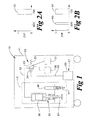
- a work machine 10 includes a work machine housing 11, within which is attached an engine 13.
- Work machine 10 can refer to any mobile machinery, including but not limited to heavy off road equipment, over the road trucks, buses, etc. Operation of engine 13 is controlled by an electronic control module 20 in a conventional manner.
- Engine 13 includes a plurality of cylinders (not shown).
- fuel injectors 40 include a tip 41 that is positioned in the engine cylinder and exposed to heat generated therein both through combustion and engine braking.
- Each cylinder includes an individual fuel injector 40 and at least one electronically controlled exhaust valve 35.
- engine 13 would be a diesel engine, and fuel injectors 40 and exhaust valves 35 would be electronically controlled hydraulically actuated systems that share a common actuation fluid, such as pressurized lubricating oil.
- electronically controlled exhaust valve 35 includes an exhaust valve, a hydraulic exhaust valve actuator 36 and an exhaust valve member 37.
- Exhaust valve actuator 36 can be connected via an actuation fluid line 32 to either a source of high pressure actuation fluid 30 or a low pressure actuation fluid reservoir 31, depending upon the position of control valve 22.
- Control valve 22 includes a control valve member 23 that is attached to an electrical actuator 24, such as a solenoid or a piezo electric actuator, and biased to the position shown by a biaser, such as a spring 25.
- Electrical actuator 24 is in control communication with electronic control module 20 via control communication line 26 in a conventional manner.
- FIGs 2a and 2b graphs of exhaust valve position (EVP) verses cylinder position is illustrated. Zero (0) being when the valve is closed and one (1) corresponding to the valve being open.
- the single event engine braking blow down 50 occurs over a span of crank angle that typically begins some number of degrees before top dead center (TDC) and often ends some number of degrees into what would be the power stroke of the engine.
- Figure 2b shows that a boost event 60 in a dual event engine braking cycle is positioned at or near when the piston is at bottom dead center (BDC).
- BDC bottom dead center
- the blow down event 61 for the dual event engine braking is much the same as that of the single event shown in 2a.
- the blow down event can consume a substantial portion of crank angle, which can be on the order of 20° to 70° depending upon engine speed.
- crank angle can be on the order of 20° to 70° depending upon engine speed.
- the exhaust valve can only be opened so far when the piston is near top dead center such that a substantial flow restriction exists at the valve seat. This in turn results in a requirement of some substantial duration of time for the pressure within the cylinder to be fully released.
- boost event 60 it preferably should be timed to correspond to the blow down event of another neighboring cylinder so that the pressure wave arrives at the appropriate cylinder at the right timing to raise the initial pressure for the two event engine braking cycle.
- timing of the boost event 64 might be slightly different for different cylinders in order to compensate for the distances over which the pressure wave must travel, etc.
- dual event braking horsepower can be further increased by appropriate adjustments to a variable geometry turbine.
- the flow area past the exhaust valve can be made greater, such as by the use of valves that open in the reverse direction, the duration of the blow down events could be substantially shortened.
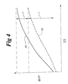
- braking horsepower (BHP) is graphed against blow down timing (BDT) that is expressed as crank angle for both dual event (DE) and single event (SE) engine braking.
- BDT blow down timing
- ES engine speed
- H high range
- L a lower range over which the desired amount of exhaust braking horsepower can be achieved with either a dual event or a single event strategy.
- the present invention is concerned with equipping the electronic control module with appropriate logic to choose between dual event or single event engine braking strategies based upon various concerns such as injector tip temperature, noise levels, turbine speed and possibly energy consumption concerns.
- injector tip temperature must generally be estimated based upon a correlation with other available sensory data because it is generally not realistic to position a temperature sensor at a location that could suitably and reliably monitor injector tip temperatures. It has been observed that the injector tip temperature almost never approach the tempering temperature when engine braking with a single event strategy.
- look- up tables of injector tip temperature would be created through correlations with engine speed and the number of previous braking cycles that precede the time at which the injector tip temperature is being estimated. For instance, when multiple braking events are happening in succession at a relatively higher engine speed, the injector tip tends to get hotter faster. When there have been no previous braking events but the engine is still at high speed, the injector tip may not yet be in danger of approaching its tempering temperature. Thus, through suitable testing, those skilled in the art could develop tables that could be used to estimate injector tip temperatures based upon variables such as engine speed, previous number of braking cycles, etc. that contribute to changes in injector tip temperatures. The concern regarding injector tip temperature relates to the possibility of catastrophic engine damage in the event of tip breakage due to accelerated fatigue failure.
- turbine speed is monitored and the characteristics of the engine braking events are altered if turbine speed exceeds a pre-determined threshold.
- noise concerns might also be a grounds for altering an engine braking event. For instance, a dual event with an advanced blow down timing might produce the same amount of braking horsepower as a single event done at or near top dead center. However, the dual event with the earlier blow down would likely produce less noise, and may present the more desirable route especially in cases, such as in cities, where reduced noise levels are mandated.
- a software flow diagram is illustrated that represents a preferred software strategy for incorporation into the electronic control module according to the present invention.
- the desired braking horsepower is determined.
- the origin of this signal could include a variety of factors such as brake pedal position, the speed of the work machine, engine speed, cruise control concerns, etc.
- the first question asked is whether the injector tip temperature is too high. If so, the system commands a single event braking cycle, since it has been determined that single event braking rarely or never exacerbates injector tip temperature. Alternatively, if the tip temperature is not too high, another question asked is whether dual event braking is desired. Depending on the particular application, a number of considerations would go into answering this question. For instance, some applications may prefer to default toward dual event braking if system parameters indicate that dual event braking is available. In other applications, there might be the preferred desirability toward single event exhaust braking unless certain conditions known in the art are present.
- the next step is to determine the timing of the blow down event. For instance, if single event braking is chosen and the desired braking horsepower is beyond that possible with a single event braking, the timing that would correspond to the maximum possible single event braking would be chosen. On the other hand, if the desired braking horsepower is lower than the maximum power available, then the blow down event timing is advanced as per the graph of Figure 3 so that the actual braking horsepower corresponds to the desired braking horsepower. The same considerations also go into determining the blow down timing for a dual event braking cycle if that it chosen.
- the next step is to ascertain whether the turbine speed is too high. If so, the system either commands the braking blow down event to advance in timing, which will result in less braking horsepower, or command an adjustment to the turbin to prevent turbine overspeed or possibly both.
- the next question is to determine whether the braking event will produce too much noise. If so, the timing of the blow down event is again advanced in order to reduce the noise output from the braking event. However, those skilled in the art will recognize that any timing advance will result in a corresponding reduction in the braking horsepower. Thus, if turbine speed is too high and/or noise levels exceed the predetermine maximum it is likely that the system will command an advanced timing braking event that will produce less braking horsepower than the desired braking horsepower. In these instances, the additional braking horsepower would need to be made up by other means, such as conventional wheel brakes or other known strategies.
- the desired braking horsepower is determined.
- the origin of this signal would include a variety of factors such as brake pedal position, cruise control concerns, etc.
- the next step is to determine whether it is beyond the braking horsepower possible with a maximum dual event. If so, the braking horsepower is set to be equal to the maximum dual event for that engine speed. Otherwise, a dual event strategy with an advanced timing is tentatively chosen in order to match the expected braking horsepower with the desired braking horsepower.
- the electronic control module takes in various sensor inputs 27 (Fig. 1) in order to estimate the injector tip temperatures. As stated earlier, this is preferably accomplished with a look-up table that correlates engine speed to injector tip temperatures. A more sophisticated approach might also factor in the number of previous recent braking cycles in order to make the temperature estimate even more accurate.
- the electronic control module compares the estimated tip temperature to a pre-determined maximum temperature, which is preferably some number of degrees below the tempering temperature of the injector tip. If the injector tip temperatures are too high, the ECM tentatively changes from a dual event strategy to a maximum single event strategy. Thus, at this point the electronic control module has affectivity chosen a maximum braking horsepower that can be achieved without risking overheated injector tips.
- the electronic control module checks to see if the maximum single event braking strategy presents a danger of turbine overspeed. If turbine overspeed is a problem at that time, the electronic control module further reduces the exhaust braking horsepower by advancing the blow down timing of the single event, or by commanding a turbine adjustment, or both.
- the expected noise output is compared to a maximum allowable noise output. If the expected noise produced by the then calculated engine braking event is too loud, the timing of the blow down event is further advanced to a point that the noise produced is acceptable. Finally, after going through this logic, the electronic control module is prepared to command either a maximum or advanced timing single event engine braking cycle.
- the electronic control module determines whether the desired braking horsepower is in the higher or lower range. If in the lower range, the next question asked by the electronic control module is whether the injector tip temperatures are exceeding a pre-determined maximum. If injector tip temperatures are ok, then the electronic control module chooses a dual event engine braking strategy. After tentatively choosing a dual event strategy, the ECM goes through a turbine speed check and a noise production test that could result in advancing the timing of the dual event in order to prevent turbine overspeed or to lower noise production. Eventually, after proceeding through this logic, the electronic control module is prepared to command a maximum or advanced timing dual event braking strategy.
- the electronic control module tentatively chooses a maximum single event exhaust braking strategy. Otherwise, an advanced timing single event strategy is chosen to correspond the expected exhaust braking horsepower to the desired braking horsepower. After this determination, the electronic control module proceeds through the turbine speed check and noise production tests to possibly advance the timing of the blow down event to prevent turbine overspeed or to prevent the over production of noise. Finally, the electronic control module arrives at position of being prepared to command either a maximum or advanced timing single event exhaust braking cycle.
- the process of determining whether the injector tip temperatures are in an acceptable range is preferably accomplished by initially measuring at least one variable that is common, such as engine speed, exhaust temperature and the number of previous exhaust braking cycles, that are correlated to injector tip temperature. Next, the injector tip temperatures are estimated based upon these sensed variables. The step of estimating the injector tip temperature could be accomplished by accessing a look-up table using the sensed variables as the coordinates in the table.
- One enhancement on the present invention might be an override exhaust braking strategy in the event that an emergency condition is detected. For instance, if a potential engine overspeed condition is detected, the electronic control module may go into an override strategy that demands the maximum possible exhaust braking at that given engine speed without regard to injector tip temperatures, turbine speed or noise. The reason for this strategy is that it is better to destroy a turbine or overheat an injector and/or produce too much noise than it is to overspeed and possibly destroy a complete engine. Such an emergency condition could occur, for example, in a runaway down hill truck.
- the exhaust braking would preferably occur in a two cycle mode such that an exhaust braking event would occur with each upward stroke of the piston for a given cylinder.
- the present invention contemplates a single exhaust braking event for each two revolutions of the engine's crank shaft as in a conventional four cycle mode.
- the present invention also contemplates the potential to selectively apply this strategy on an individual cylinder basis. For example, some brake actuators could operate in a dual event mode while others cool in a single event mode. The control could then cycle the injectors that are in the single event (or cooling) mode.
- the present invention also contemplates the possibility of using less than all available exhaust brake actuators to perform engine braking events. For instance, various concerns might make it desirable to use less than all of the engine brake actuators with blow downs near top dead center rather than advanced timing blow downs using all available engine brake actuators.
- the desired magnitude of engine braking horsepower might be such that the electronic control module need only command less than all of the engine valve actuators in order to produce the desired amount of engine braking.
Landscapes
- Engineering & Computer Science (AREA)
- Chemical & Material Sciences (AREA)
- Combustion & Propulsion (AREA)
- Mechanical Engineering (AREA)
- General Engineering & Computer Science (AREA)
- Electrical Control Of Air Or Fuel Supplied To Internal-Combustion Engine (AREA)
- Output Control And Ontrol Of Special Type Engine (AREA)
- Supercharger (AREA)
Applications Claiming Priority (2)
| Application Number | Priority Date | Filing Date | Title |
|---|---|---|---|
| US74040500A | 2000-12-19 | 2000-12-19 | |
| US740405 | 2000-12-19 |
Publications (3)
| Publication Number | Publication Date |
|---|---|
| EP1217193A2 true EP1217193A2 (fr) | 2002-06-26 |
| EP1217193A3 EP1217193A3 (fr) | 2004-06-16 |
| EP1217193B1 EP1217193B1 (fr) | 2009-05-20 |
Family
ID=24976362
Family Applications (1)
| Application Number | Title | Priority Date | Filing Date |
|---|---|---|---|
| EP01124672A Expired - Lifetime EP1217193B1 (fr) | 2000-12-19 | 2001-10-16 | Commande électronique d'un cycle de freinage de moteur |
Country Status (3)
| Country | Link |
|---|---|
| US (1) | US6609495B1 (fr) |
| EP (1) | EP1217193B1 (fr) |
| DE (1) | DE60138748D1 (fr) |
Cited By (1)
| Publication number | Priority date | Publication date | Assignee | Title |
|---|---|---|---|---|
| WO2020058413A1 (fr) * | 2018-09-19 | 2020-03-26 | Eaton Intelligent Power Limited | Ensemble de train de soupapes |
Families Citing this family (14)
| Publication number | Priority date | Publication date | Assignee | Title |
|---|---|---|---|---|
| GB0203490D0 (en) * | 2002-02-14 | 2002-04-03 | Holset Engineering Co | Exhaust brake control system |
| US9154906B2 (en) | 2002-03-28 | 2015-10-06 | Telecommunication Systems, Inc. | Area watcher for wireless network |
| US6993426B2 (en) * | 2003-07-14 | 2006-01-31 | Detroit Diesel Corporation | Method of engine overspeed protection by inhibiting operator throttle input |
| US6877486B2 (en) * | 2003-09-15 | 2005-04-12 | General Motors Corporation | Method and apparatus for predicting a fuel injector tip temperature |
| KR100622482B1 (ko) | 2004-05-20 | 2006-09-19 | 현대자동차주식회사 | 차량 엔진의 연료량 보정방법 |
| EP1880095B1 (fr) * | 2005-05-13 | 2008-10-08 | Daimler AG | Processus de freinage moteur a deux temps pour un moteur a combustion interne suralimente |
| US20090090332A1 (en) * | 2007-10-03 | 2009-04-09 | Brehob Diana D | Method and System to Mitigate Deposit Formation on a Direct Injector for a Gasoline-Fuelled Internal Combustion Engine |
| US8214113B2 (en) * | 2008-06-30 | 2012-07-03 | Caterpillar Inc. | Retarding system that retards motion of power source |
| US8688402B2 (en) * | 2009-09-23 | 2014-04-01 | Robert Bosch Gmbh | Systems and methods for estimating a temperature of a fluid injector used in a hot environment |
| TR201809346T4 (tr) | 2012-06-14 | 2018-07-23 | Gm Global Tech Operations Llc | Çok yakıtlı sistemli bir içten yanmalı motorda yakıt sistemi koruması. |
| US20140214308A1 (en) * | 2013-01-29 | 2014-07-31 | Cummins Ip, Inc. | Apparatus, system and method for increasing braking power |
| US10801417B1 (en) * | 2019-07-12 | 2020-10-13 | GM Global Technology Operations LLC | Methods and systems for regulating exhaust gas flow |
| US11668255B2 (en) | 2020-12-09 | 2023-06-06 | Caterpillar Inc. | Engine braking method and control system varying engine braking power within cylinder-number braking mode |
| CN119825563B (zh) * | 2025-01-17 | 2025-10-24 | 潍柴动力股份有限公司 | 一种喷油器油头温度的降低方法及相关装置 |
Citations (1)
| Publication number | Priority date | Publication date | Assignee | Title |
|---|---|---|---|---|
| US5724939A (en) | 1996-09-05 | 1998-03-10 | Caterpillar Inc. | Exhaust pulse boosted engine compression braking method |
Family Cites Families (20)
| Publication number | Priority date | Publication date | Assignee | Title |
|---|---|---|---|---|
| US3220392A (en) | 1962-06-04 | 1965-11-30 | Clessie L Cummins | Vehicle engine braking and fuel control system |
| US3684318A (en) * | 1970-05-22 | 1972-08-15 | Gen Motors Corp | Fuel rail-injector interconnection |
| US4014297A (en) * | 1975-05-07 | 1977-03-29 | General Motors Corporation | Rotary engine combustion control arrangement |
| DE3900739A1 (de) | 1989-01-12 | 1990-07-19 | Man Nutzfahrzeuge Ag | Verfahren zur steigerung der motorbremsleistung bei viertakt-hubkolben-brennkraftmaschinen |
| SE466320B (sv) | 1989-02-15 | 1992-01-27 | Volvo Ab | Foerfarande och anordning foer motorbromsning med en fyrtakts foerbraenningsmotor |
| DE3922884A1 (de) | 1989-07-12 | 1991-01-24 | Man Nutzfahrzeuge Ag | Motorbremse fuer luftverdichtende brennkraftmaschinen |
| US6148258A (en) * | 1991-10-31 | 2000-11-14 | Nartron Corporation | Electrical starting system for diesel engines |
| US5255650A (en) | 1992-06-01 | 1993-10-26 | Caterpillar Inc. | Engine braking utilizing unit valve actuation |
| US5386809A (en) | 1993-10-26 | 1995-02-07 | Cummins Engine Company, Inc. | Pressure relief valve for compression engine braking system |
| FR2712026B1 (fr) * | 1993-11-05 | 1996-01-12 | Siemens Automotive Sa | Procédé et dispositif de commande de la levée d'une soupape d'un moteur à combustion interne. |
| US5813231A (en) | 1994-07-29 | 1998-09-29 | Caterpillar Inc. | Engine compression braking apparatus utilizing a variable geometry turbocharger |
| US5647318A (en) | 1994-07-29 | 1997-07-15 | Caterpillar Inc. | Engine compression braking apparatus and method |
| US5718199A (en) | 1994-10-07 | 1998-02-17 | Diesel Engine Retarders, Inc. | Electronic controls for compression release engine brakes |
| US5537976A (en) | 1995-08-08 | 1996-07-23 | Diesel Engine Retarders, Inc. | Four-cycle internal combustion engines with two-cycle compression release braking |
| US5634447A (en) | 1996-03-07 | 1997-06-03 | Navistar International Transportation Corp. | Electronic fuel injection augmentation of an engine compression brake |
| US5787858A (en) | 1996-10-07 | 1998-08-04 | Meneely; Vincent Allan | Engine brake with controlled valve closing |
| US6000374A (en) | 1997-12-23 | 1999-12-14 | Diesel Engine Retarders, Inc. | Multi-cycle, engine braking with positive power valve actuation control system and process for using the same |
| JPH11351041A (ja) * | 1998-06-08 | 1999-12-21 | Fuji Heavy Ind Ltd | 燃料噴射式内燃機関 |
| JP3494927B2 (ja) * | 1999-08-25 | 2004-02-09 | 株式会社日本自動車部品総合研究所 | インジェクタデポジットの評価方法及び評価装置 |
| US6283091B1 (en) * | 2000-01-14 | 2001-09-04 | Mack Trucks, Inc. | Method and apparatus for controlling nozzle temperature during engine braking |
-
2001
- 2001-09-14 US US09/952,823 patent/US6609495B1/en not_active Expired - Lifetime
- 2001-10-16 EP EP01124672A patent/EP1217193B1/fr not_active Expired - Lifetime
- 2001-10-16 DE DE60138748T patent/DE60138748D1/de not_active Expired - Fee Related
Patent Citations (1)
| Publication number | Priority date | Publication date | Assignee | Title |
|---|---|---|---|---|
| US5724939A (en) | 1996-09-05 | 1998-03-10 | Caterpillar Inc. | Exhaust pulse boosted engine compression braking method |
Cited By (1)
| Publication number | Priority date | Publication date | Assignee | Title |
|---|---|---|---|---|
| WO2020058413A1 (fr) * | 2018-09-19 | 2020-03-26 | Eaton Intelligent Power Limited | Ensemble de train de soupapes |
Also Published As
| Publication number | Publication date |
|---|---|
| EP1217193B1 (fr) | 2009-05-20 |
| DE60138748D1 (de) | 2009-07-02 |
| EP1217193A3 (fr) | 2004-06-16 |
| US6609495B1 (en) | 2003-08-26 |
Similar Documents
| Publication | Publication Date | Title |
|---|---|---|
| EP1217193B1 (fr) | Commande électronique d'un cycle de freinage de moteur | |
| US5718199A (en) | Electronic controls for compression release engine brakes | |
| CA2047219C (fr) | Une methode et un dispositif pour le freinage par moteur d'un moteur a combustion interne | |
| US7077082B2 (en) | System and method for monitoring engine valve actuation | |
| CA2359524C (fr) | Methode et dispositif d'activation d'un frein moteur | |
| JP4426652B2 (ja) | 油圧作動式電子制御燃料噴射システムの異なった種類の噴射波形使用の移行を制御する方法 | |
| CN101290262A (zh) | 用于检测液压流体泄漏的系统 | |
| US11668255B2 (en) | Engine braking method and control system varying engine braking power within cylinder-number braking mode | |
| US6216667B1 (en) | Method and device for a supercharged engine brake | |
| US7228828B2 (en) | Control system and method for a valve actuator | |
| US5634447A (en) | Electronic fuel injection augmentation of an engine compression brake | |
| JP4519133B2 (ja) | エンジンブレーキ制御圧力ストラテジー | |
| US6418720B1 (en) | Method and a device for engine braking a four stroke internal combustion engine | |
| JP2003247433A (ja) | 排気ブレーキ制御装置 | |
| AU662899B2 (en) | Method for coldstarting a piston engine and means for carrying out the method | |
| US7441519B2 (en) | Engine valve actuation system | |
| EP3132133B1 (fr) | Moteur à combustion interne avec un système de pompe à carburant à injection directe à course variable et procédé pour contrôler le moteur | |
| US6205975B1 (en) | Method and apparatus for controlling the actuation of a compression brake | |
| WO2019151928A1 (fr) | Agencement de freinage par décompression, procédé de commande d'agencement de freinage par décompression, et dispositifs associés | |
| US6568367B2 (en) | Engine compression release brake system and method of operation | |
| US20180328240A1 (en) | Hydraulic Early Engine Exhaust Valve Opening System | |
| US20040065285A1 (en) | Variable engine valve actuator | |
| US6715467B2 (en) | Method and apparatus for engine braking | |
| Howell et al. | Vehicle demonstration of 2 stroke engine brake in a heavy duty truck | |
| JP2021055607A (ja) | エンジンシステム及びエンジンシステムの制御装置 |
Legal Events
| Date | Code | Title | Description |
|---|---|---|---|
| PUAI | Public reference made under article 153(3) epc to a published international application that has entered the european phase |
Free format text: ORIGINAL CODE: 0009012 |
|
| AK | Designated contracting states |
Kind code of ref document: A2 Designated state(s): AT BE CH CY DE DK ES FI FR GB GR IE IT LI LU MC NL PT SE TR |
|
| AX | Request for extension of the european patent |
Free format text: AL;LT;LV;MK;RO;SI |
|
| PUAL | Search report despatched |
Free format text: ORIGINAL CODE: 0009013 |
|
| AK | Designated contracting states |
Kind code of ref document: A3 Designated state(s): AT BE CH CY DE DK ES FI FR GB GR IE IT LI LU MC NL PT SE TR |
|
| AX | Request for extension of the european patent |
Extension state: AL LT LV MK RO SI |
|
| RIC1 | Information provided on ipc code assigned before grant |
Ipc: 7F 01L 13/06 B Ipc: 7F 01L 9/02 B Ipc: 7F 02D 13/04 A |
|
| 17P | Request for examination filed |
Effective date: 20041129 |
|
| AKX | Designation fees paid |
Designated state(s): DE |
|
| 17Q | First examination report despatched |
Effective date: 20071221 |
|
| GRAP | Despatch of communication of intention to grant a patent |
Free format text: ORIGINAL CODE: EPIDOSNIGR1 |
|
| GRAS | Grant fee paid |
Free format text: ORIGINAL CODE: EPIDOSNIGR3 |
|
| GRAA | (expected) grant |
Free format text: ORIGINAL CODE: 0009210 |
|
| AK | Designated contracting states |
Kind code of ref document: B1 Designated state(s): DE |
|
| REF | Corresponds to: |
Ref document number: 60138748 Country of ref document: DE Date of ref document: 20090702 Kind code of ref document: P |
|
| PLBE | No opposition filed within time limit |
Free format text: ORIGINAL CODE: 0009261 |
|
| STAA | Information on the status of an ep patent application or granted ep patent |
Free format text: STATUS: NO OPPOSITION FILED WITHIN TIME LIMIT |
|
| 26N | No opposition filed |
Effective date: 20100223 |
|
| PG25 | Lapsed in a contracting state [announced via postgrant information from national office to epo] |
Ref country code: DE Free format text: LAPSE BECAUSE OF NON-PAYMENT OF DUE FEES Effective date: 20100501 |