EP1219418A2 - Machine pour la décoration en continu de surfaces de produits et plus particulièrement de carreaux en céramique - Google Patents
Machine pour la décoration en continu de surfaces de produits et plus particulièrement de carreaux en céramique Download PDFInfo
- Publication number
- EP1219418A2 EP1219418A2 EP01128482A EP01128482A EP1219418A2 EP 1219418 A2 EP1219418 A2 EP 1219418A2 EP 01128482 A EP01128482 A EP 01128482A EP 01128482 A EP01128482 A EP 01128482A EP 1219418 A2 EP1219418 A2 EP 1219418A2
- Authority
- EP
- European Patent Office
- Prior art keywords
- drum
- decoration
- machine according
- printing machine
- decoration printing
- Prior art date
- Legal status (The legal status is an assumption and is not a legal conclusion. Google has not performed a legal analysis and makes no representation as to the accuracy of the status listed.)
- Withdrawn
Links
Images


Classifications
-
- B—PERFORMING OPERATIONS; TRANSPORTING
- B41—PRINTING; LINING MACHINES; TYPEWRITERS; STAMPS
- B41F—PRINTING MACHINES OR PRESSES
- B41F15/00—Screen printers
- B41F15/14—Details
- B41F15/40—Inking units
- B41F15/405—Spraying apparatus
-
- B—PERFORMING OPERATIONS; TRANSPORTING
- B41—PRINTING; LINING MACHINES; TYPEWRITERS; STAMPS
- B41F—PRINTING MACHINES OR PRESSES
- B41F15/00—Screen printers
- B41F15/08—Machines
- B41F15/0804—Machines for printing sheets
- B41F15/0809—Machines for printing sheets with cylindrical or belt-like screens
-
- B—PERFORMING OPERATIONS; TRANSPORTING
- B41—PRINTING; LINING MACHINES; TYPEWRITERS; STAMPS
- B41P—INDEXING SCHEME RELATING TO PRINTING, LINING MACHINES, TYPEWRITERS, AND TO STAMPS
- B41P2215/00—Screen printing machines
- B41P2215/10—Screen printing machines characterised by their constructional features
- B41P2215/13—Devices for increasing ink penetration
- B41P2215/132—Devices for increasing ink penetration by increasing pressure above the screen
-
- B—PERFORMING OPERATIONS; TRANSPORTING
- B41—PRINTING; LINING MACHINES; TYPEWRITERS; STAMPS
- B41P—INDEXING SCHEME RELATING TO PRINTING, LINING MACHINES, TYPEWRITERS, AND TO STAMPS
- B41P2217/00—Printing machines of special types or for particular purposes
- B41P2217/50—Printing presses for particular purposes
- B41P2217/56—Printing presses for particular purposes for printing ceramic tiles
Definitions
- the present invention relates to a machine for continuous surface decoration of products, particularly ceramic tiles.
- These machines substantially consist of a frame that supports a portion of tile conveyor, above which a decorating drum is mounted; such drum is rotatable about a horizontal axis and lies transversely to the advancement direction of the conveyor.
- Such drum can be composed of printing screens which are pre-perforated according to the design or composed of a substantially rigid supporting cylindrical core covered, on its outer surface, by a layer of silicone material whose perimetric face is engraved by means of a laser beam so as to reproduce in bas-relief the design to be applied to the tiles.
- Application occurs by moving the tiles in a row on the conveyor below the drum, arranged so that its outer surface rolls without slipping on the surfaces of the tiles, transferring onto them by rolling contact the designs, whether produced on printing screens or on silicone matrices.
- a second drawback of these machines, especially for silicone-matrix ones, is that in order to provide the decorations it is necessary to have a very expensive laser-beam apparatus to engrave the various matrices according to the design.
- a third drawback, linked to decoration printing machines that use pre-perforated printing screens, is that since in order to satisfactorily transfer the decoration such screens must be pressed in the contact region by a spatula or doctor, which is also designed to spread the glazes on the inner part of the screen in order to make them pass through the perforations according to the design, such screens have a substantially short life owing to continuous friction with the lip of the spatula.
- the aim of the present invention is to eliminate the above noted drawbacks of the known art by providing a machine for the continuous surface decoration of products, particularly ceramic tiles, that allows to produce continuous decorations on any kind of product even with surfaces affected by raised and recessed portions, without having early wear phenomena and at significantly low costs.
- the present machine for the continuous surface decoration of products, particularly ceramic tiles, which comprises a frame that supports a substantially horizontal portion of a product conveyor, above the upper active portion of which a decorating drum is mounted which has a horizontal axis arranged transversely to the direction of advancement of the conveyor, characterized in that said drum is supported by said frame in a slightly raised position, without contact with the surfaces of the products to be decorated, the perimetric surface of said decorating drum being perforated according to a design for the passage, from the inside outward, of glazes propelled by a stream of gaseous fluid ejected under pressure from the end portion of a corresponding ejector located inside said drum at the decoration region.
- the reference numeral 1 generally designates a machine for the continuous surface decoration of products, particularly ceramic tiles 2.
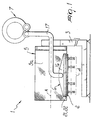
- the decoration printing machine 1 comprises a frame 3 that supports a substantially horizontal portion of a conveyor 4 for the tiles 2 or for other products, above the upper active portion of which a decorating drum 5 is mounted that is supported on the frame 3 with an axis A that is horizontal and transverse with respect to the advancement direction of the conveyor 4.
- the drum 5 is supported by said frame 3 in an adjustable manner, by way of means that are known to the person skilled in the art, so as to be slightly raised from the tiles 2 by an extent ⁇ that amounts to a few millimeters, i.e., without contact with the surfaces to be decorated.
- the perimetric surface 5a of the decorating drum 5 is perforated according to the design in order to allow the passage, from the inside outward, of glazes propelled by a stream of gaseous fluid ejected under pressure from the end portion 6 of a corresponding ejector 7 accommodated inside the drum 5 at the decorating region 8, with interposed means 9 for adjusting vertical height.
- the stream of fluid constituted in practice by air under pressure, has a laminar flow and is directed substantially at right angles to the internal surface of the drum 5.
- first scraper means 10a With a variable contact angle are provided for removing any remaining glaze residues, said first scraper means being located upstream of said decoration region; on the inner surface, too, second scraper means 10b are provided, which also have a variable contact angle, for the uniform distribution of the glazes along the inner surface, said second scraper means being located directly upstream of the decoration region 8.
- Both the first scraper means 10a and the second scraper means 10b are constituted by corresponding doctors 11 and 12, which are supported on the frame 3 by means of interposed articulated lever systems 13 and 14 for connection thereto and have a movement system with micrometric-pitch screws in order to adjust their respective angles of incidence.
- the ejector 7 comprises a compressor 15, which is located outside the drum 5, and a laminar ejection outlet 16, which constitutes said end portion 6 and is accommodated inside said drum 5 so as to be substantially perpendicular to its internal surface and at the decoration region 8; the compressor 15 and the ejection outlet 16 are connected one another by means of a corresponding tube 17.
- the ejection outlet 16 has a box-like body in which the lower portion is flush with the inner surface of the drum 5 and is formed by two converging planes 18 and 19, which form a downward-tapering region and a funnel-shaped cross-section; at least two corresponding lips 21 and 22 are mounted in sliding contact on the surfaces of said tapering planes, converge towards each other and are adjustable as for their position by way of corresponding adjusting means 23 in order to adjust the breadth of the useful gap for the passage of the laminar flow of air under pressure.
- the adjusting means 23 for adjusting the position of said lips 21 and 22 are constituted by respective screw clamps 24, which are alternately adapted to allow or block their movement on the converging planes 18 and 19.
- Said ejection outlet 16 lies transversely parallel to the axis "A" of the drum 5 and substantially along its entire axial dimension, so as to sweep, during rotation, all of its surface 5a with the air stream.
- a glaze supply line 25 is also provided, which as an alternative, and in the presence of particular surfaces 5a, can be alternately made to exit outside said drum.
- the drum 5 is kept raised by an extent " ⁇ " from the level at which the surfaces to be decorated lie, so that there is no direct contact between said surfaces and the outer surface 5a of the drum 5.
- Said elevation of the drum 5 is adjusted by way of means that are usually known to the person skilled in the art and accordingly are not described in detail.
- the drum 5 is turned about its own longitudinal axis "A" at a rate that advantageously matches the speed at which the tiles 2 perform their translational motion on the conveyor 4.
- the decoration is applied to the surfaces of the tiles 2 by means of a jet of glaze propelled by the laminar flow of air under pressure ejected through the outlet 16; said stream, in the decoration region 8, propels the glaze deposited inside the drum 5 by a conventional supply line 25 through the holes 26 that pass through the surface 5a of the drum 5 and compose, as a whole, the decoration to be applied to the tiles 2.
- any raised or recessed decoration present on said surfaces is reached by the glaze at each monochrome application, maintaining the contours pre-perforated according to the design on each one of the decorating drums 5 mounted in succession along a conventional multiple-color decoration line.
- the thickness of the curtain of air under pressure ejected by the outlet 16 can be adjusted as required by moving apart or closer the lips 21 and 22 and locking them in position by means of the clamps 24.
- the outer surface 5a of said drum is constantly kept clean by the doctor 11, which is located downstream of the decoration region 8, while the doctor 12 internally distributes uniformly the glaze on the internal surface of the drum, directly upstream of the outlet 16.
- the angles of incidence of the doctors 11 and 12 are both adjustable and modifiable by acting on the screw-type lever systems 13 and 14.
- the drum 5 can be equally constituted by one or more printing screens of the known type, perforated according to the design, or by silicone cylindrical elements, on the surfaces of which the decorations are engraved so as to provide through passage, in order to allow permeability of the glazes from the inside outward.
- the supply line 25 can be transferred outside said drum without altering the method of glaze application.
Landscapes
- Engineering & Computer Science (AREA)
- Mechanical Engineering (AREA)
- Preparation Of Clay, And Manufacture Of Mixtures Containing Clay Or Cement (AREA)
- Finishing Walls (AREA)
- Processing Of Stones Or Stones Resemblance Materials (AREA)
- Devices For Post-Treatments, Processing, Supply, Discharge, And Other Processes (AREA)
- Printing Methods (AREA)
Applications Claiming Priority (2)
| Application Number | Priority Date | Filing Date | Title |
|---|---|---|---|
| ITMO000274 | 2000-12-15 | ||
| IT2000MO000274A IT1316968B1 (it) | 2000-12-15 | 2000-12-15 | Decoratrice superficiale in continuo di prodotti, particolarmentepiastrelle ceramiche. |
Publications (2)
| Publication Number | Publication Date |
|---|---|
| EP1219418A2 true EP1219418A2 (fr) | 2002-07-03 |
| EP1219418A3 EP1219418A3 (fr) | 2003-11-05 |
Family
ID=11450640
Family Applications (1)
| Application Number | Title | Priority Date | Filing Date |
|---|---|---|---|
| EP01128482A Withdrawn EP1219418A3 (fr) | 2000-12-15 | 2001-12-06 | Machine pour la décoration en continu de surfaces de produits et plus particulièrement de carreaux en céramique |
Country Status (3)
| Country | Link |
|---|---|
| EP (1) | EP1219418A3 (fr) |
| BR (1) | BR0106139A (fr) |
| IT (1) | IT1316968B1 (fr) |
Cited By (1)
| Publication number | Priority date | Publication date | Assignee | Title |
|---|---|---|---|---|
| WO2006024552A1 (fr) * | 2004-09-03 | 2006-03-09 | Sichenia Gruppo Ceramiche S.P.A. | Machine d'impression par serigraphie par voie humide d'elements essentiellement plats, tels que notamment des articles en ceramique |
Citations (2)
| Publication number | Priority date | Publication date | Assignee | Title |
|---|---|---|---|---|
| EP0749844A1 (fr) | 1995-06-19 | 1996-12-27 | Riso Kagaku Corporation | Machine d'impression à stencil |
| WO1999041081A1 (fr) | 1998-02-13 | 1999-08-19 | Stork Textile Printing Group B.V. | Dispositif et procede d'application d'une substance sur un substrat, systeme comprenant plusieurs de ces dispositifs et utilisation de ces dispositif, procede et systeme |
Family Cites Families (2)
| Publication number | Priority date | Publication date | Assignee | Title |
|---|---|---|---|---|
| AT393246B (de) * | 1989-03-31 | 1991-09-10 | Hwb Maschinenbau | Auftragsvorrichtung zum aufbringen fliessfaehiger medien auf ebene flaechen, bahnen, walzen od. dgl. |
| EP1157832A1 (fr) * | 2000-05-15 | 2001-11-28 | Tecno-Italia S.R.L. | Dispositif d'impression pour machines de sérigraphie. |
-
2000
- 2000-12-15 IT IT2000MO000274A patent/IT1316968B1/it active
-
2001
- 2001-12-06 EP EP01128482A patent/EP1219418A3/fr not_active Withdrawn
- 2001-12-14 BR BR0106139-9A patent/BR0106139A/pt not_active Application Discontinuation
Patent Citations (2)
| Publication number | Priority date | Publication date | Assignee | Title |
|---|---|---|---|---|
| EP0749844A1 (fr) | 1995-06-19 | 1996-12-27 | Riso Kagaku Corporation | Machine d'impression à stencil |
| WO1999041081A1 (fr) | 1998-02-13 | 1999-08-19 | Stork Textile Printing Group B.V. | Dispositif et procede d'application d'une substance sur un substrat, systeme comprenant plusieurs de ces dispositifs et utilisation de ces dispositif, procede et systeme |
Cited By (1)
| Publication number | Priority date | Publication date | Assignee | Title |
|---|---|---|---|---|
| WO2006024552A1 (fr) * | 2004-09-03 | 2006-03-09 | Sichenia Gruppo Ceramiche S.P.A. | Machine d'impression par serigraphie par voie humide d'elements essentiellement plats, tels que notamment des articles en ceramique |
Also Published As
| Publication number | Publication date |
|---|---|
| ITMO20000274A1 (it) | 2002-06-15 |
| IT1316968B1 (it) | 2003-05-13 |
| EP1219418A3 (fr) | 2003-11-05 |
| ITMO20000274A0 (it) | 2000-12-15 |
| BR0106139A (pt) | 2002-08-13 |
Similar Documents
| Publication | Publication Date | Title |
|---|---|---|
| US5145529A (en) | System for coating strips of backing | |
| JPH07330472A (ja) | 回転式の釉及び装飾を施す、特にセラミック・タイル用の装置 | |
| EP1986830B1 (fr) | Procede et appareil de decoration avec materiau en poudre | |
| US4395949A (en) | Sheet transport drum assembly in a rotary printing press | |
| ITMO20070354A1 (it) | Apparato e metodo per decorare oggetti | |
| CN101360591B (zh) | 用于装饰陶瓷产品的设备 | |
| US6458211B1 (en) | Device and method for applying a medium to a substrate, system having a plurality of such devices, and use of such device, method and system | |
| EP1162047B1 (fr) | Dispositif pour distribuer suivant un dessin déterminé des matériaux pulvérulents sur un support | |
| EP1034905B1 (fr) | Dispositif pour déposer des couches d'émail et de matériaux similaires sur des objets en céramique | |
| CN118742686A (zh) | 涂布喷嘴、涂布装置和方法 | |
| JPH07110346B2 (ja) | 塗工装置及び巻取紙塗布方法 | |
| EP1219418A2 (fr) | Machine pour la décoration en continu de surfaces de produits et plus particulièrement de carreaux en céramique | |
| CN101384405B (zh) | 使用粉末材料的装饰方法 | |
| JP4142648B2 (ja) | 粉末を担体上に予め定めたパターンで分布させる装置 | |
| CN101316662B (zh) | 涂覆方法和装置 | |
| US6971310B1 (en) | Method of operation of a printing unit and printing unit for offset machine | |
| EP1208953A2 (fr) | Moyens de décoration | |
| EP1847364A1 (fr) | Machine rotative de décoration et d'impression | |
| RU2258008C2 (ru) | Система дозирования для накатывания краски на валики в печатной машине | |
| JP3929605B2 (ja) | 塗装装置 | |
| FR2526332A1 (fr) | Appareil d'application de revetement | |
| JPH0559697A (ja) | 塗抹装置 | |
| ITMO930166A1 (it) | Metodo per la decorazione a smalto di manufatti a superficie piana o non piana, macchina e prodotto relativi. | |
| ITMO930165A1 (it) | Metodo per la decorazione serigrafica, ad umido, di elementi piatti, macchina e prodotto relativi. | |
| JPH0580566U (ja) | 塗工装置 |
Legal Events
| Date | Code | Title | Description |
|---|---|---|---|
| PUAI | Public reference made under article 153(3) epc to a published international application that has entered the european phase |
Free format text: ORIGINAL CODE: 0009012 |
|
| AK | Designated contracting states |
Kind code of ref document: A2 Designated state(s): AT BE CH CY DE DK ES FI FR GB GR IE IT LI LU MC NL PT SE TR |
|
| AX | Request for extension of the european patent |
Free format text: AL;LT;LV;MK;RO;SI |
|
| PUAL | Search report despatched |
Free format text: ORIGINAL CODE: 0009013 |
|
| AK | Designated contracting states |
Kind code of ref document: A3 Designated state(s): AT BE CH CY DE DK ES FI FR GB GR IE IT LI LU MC NL PT SE TR |
|
| AX | Request for extension of the european patent |
Extension state: AL LT LV MK RO SI |
|
| TPAC | Observations filed by third parties |
Free format text: ORIGINAL CODE: EPIDOSNTIPA |
|
| AKX | Designation fees paid | ||
| REG | Reference to a national code |
Ref country code: DE Ref legal event code: 8566 |
|
| STAA | Information on the status of an ep patent application or granted ep patent |
Free format text: STATUS: THE APPLICATION IS DEEMED TO BE WITHDRAWN |
|
| 18D | Application deemed to be withdrawn |
Effective date: 20040701 |