EP1221610A2 - CO-Sensor und Verfahren zum Messen des CO-Gehaltes - Google Patents
CO-Sensor und Verfahren zum Messen des CO-Gehaltes Download PDFInfo
- Publication number
- EP1221610A2 EP1221610A2 EP02250041A EP02250041A EP1221610A2 EP 1221610 A2 EP1221610 A2 EP 1221610A2 EP 02250041 A EP02250041 A EP 02250041A EP 02250041 A EP02250041 A EP 02250041A EP 1221610 A2 EP1221610 A2 EP 1221610A2
- Authority
- EP
- European Patent Office
- Prior art keywords
- electrode
- measurement
- hydrogen
- concentration
- measurement space
- Prior art date
- Legal status (The legal status is an assumption and is not a legal conclusion. Google has not performed a legal analysis and makes no representation as to the accuracy of the status listed.)
- Withdrawn
Links
- 238000000034 method Methods 0.000 title description 14
- 238000005259 measurement Methods 0.000 claims abstract description 221
- UFHFLCQGNIYNRP-UHFFFAOYSA-N Hydrogen Chemical compound [H][H] UFHFLCQGNIYNRP-UHFFFAOYSA-N 0.000 claims abstract description 111
- 229910052739 hydrogen Inorganic materials 0.000 claims abstract description 103
- 239000001257 hydrogen Substances 0.000 claims abstract description 103
- 239000007789 gas Substances 0.000 claims abstract description 96
- 239000003054 catalyst Substances 0.000 claims description 16
- 238000006243 chemical reaction Methods 0.000 claims description 15
- 238000010438 heat treatment Methods 0.000 claims description 12
- 238000005086 pumping Methods 0.000 claims description 10
- 239000000126 substance Substances 0.000 claims description 8
- 238000000691 measurement method Methods 0.000 claims description 7
- OKTJSMMVPCPJKN-UHFFFAOYSA-N Carbon Chemical compound [C] OKTJSMMVPCPJKN-UHFFFAOYSA-N 0.000 description 6
- PNEYBMLMFCGWSK-UHFFFAOYSA-N aluminium oxide Inorganic materials [O-2].[O-2].[O-2].[Al+3].[Al+3] PNEYBMLMFCGWSK-UHFFFAOYSA-N 0.000 description 5
- 239000000446 fuel Substances 0.000 description 5
- 229910052799 carbon Inorganic materials 0.000 description 4
- OKKJLVBELUTLKV-UHFFFAOYSA-N Methanol Chemical compound OC OKKJLVBELUTLKV-UHFFFAOYSA-N 0.000 description 3
- 229920000557 Nafion® Polymers 0.000 description 3
- NWUYHJFMYQTDRP-UHFFFAOYSA-N 1,2-bis(ethenyl)benzene;1-ethenyl-2-ethylbenzene;styrene Chemical compound C=CC1=CC=CC=C1.CCC1=CC=CC=C1C=C.C=CC1=CC=CC=C1C=C NWUYHJFMYQTDRP-UHFFFAOYSA-N 0.000 description 2
- UGFAIRIUMAVXCW-UHFFFAOYSA-N Carbon monoxide Chemical compound [O+]#[C-] UGFAIRIUMAVXCW-UHFFFAOYSA-N 0.000 description 2
- YCKRFDGAMUMZLT-UHFFFAOYSA-N Fluorine atom Chemical compound [F] YCKRFDGAMUMZLT-UHFFFAOYSA-N 0.000 description 2
- 229910002091 carbon monoxide Inorganic materials 0.000 description 2
- 238000000354 decomposition reaction Methods 0.000 description 2
- 230000007423 decrease Effects 0.000 description 2
- 238000001514 detection method Methods 0.000 description 2
- 238000010494 dissociation reaction Methods 0.000 description 2
- 230000005593 dissociations Effects 0.000 description 2
- 238000010304 firing Methods 0.000 description 2
- 229910052731 fluorine Inorganic materials 0.000 description 2
- 239000011737 fluorine Substances 0.000 description 2
- 239000002737 fuel gas Substances 0.000 description 2
- 238000007731 hot pressing Methods 0.000 description 2
- 239000003456 ion exchange resin Substances 0.000 description 2
- 229920003303 ion-exchange polymer Polymers 0.000 description 2
- 239000000463 material Substances 0.000 description 2
- 239000011148 porous material Substances 0.000 description 2
- 239000011347 resin Substances 0.000 description 2
- 229920005989 resin Polymers 0.000 description 2
- 239000000919 ceramic Substances 0.000 description 1
- 230000006866 deterioration Effects 0.000 description 1
- 230000007613 environmental effect Effects 0.000 description 1
- UQSQSQZYBQSBJZ-UHFFFAOYSA-N fluorosulfonic acid Chemical compound OS(F)(=O)=O UQSQSQZYBQSBJZ-UHFFFAOYSA-N 0.000 description 1
- 238000005242 forging Methods 0.000 description 1
- 239000011810 insulating material Substances 0.000 description 1
- 238000003754 machining Methods 0.000 description 1
- 238000004519 manufacturing process Methods 0.000 description 1
- 229910052751 metal Inorganic materials 0.000 description 1
- 239000002184 metal Substances 0.000 description 1
- 239000000203 mixture Substances 0.000 description 1
- 239000002574 poison Substances 0.000 description 1
- 231100000614 poison Toxicity 0.000 description 1
- 239000005518 polymer electrolyte Substances 0.000 description 1
- 239000000843 powder Substances 0.000 description 1
- 238000004080 punching Methods 0.000 description 1
- 239000007787 solid Substances 0.000 description 1
- 239000000758 substrate Substances 0.000 description 1
Images


Classifications
-
- G—PHYSICS
- G01—MEASURING; TESTING
- G01N—INVESTIGATING OR ANALYSING MATERIALS BY DETERMINING THEIR CHEMICAL OR PHYSICAL PROPERTIES
- G01N27/00—Investigating or analysing materials by the use of electric, electrochemical, or magnetic means
- G01N27/26—Investigating or analysing materials by the use of electric, electrochemical, or magnetic means by investigating electrochemical variables; by using electrolysis or electrophoresis
- G01N27/403—Cells and electrode assemblies
- G01N27/406—Cells and probes with solid electrolytes
- G01N27/407—Cells and probes with solid electrolytes for investigating or analysing gases
- G01N27/4073—Composition or fabrication of the solid electrolyte
- G01N27/4074—Composition or fabrication of the solid electrolyte for detection of gases other than oxygen
-
- G—PHYSICS
- G01—MEASURING; TESTING
- G01N—INVESTIGATING OR ANALYSING MATERIALS BY DETERMINING THEIR CHEMICAL OR PHYSICAL PROPERTIES
- G01N33/00—Investigating or analysing materials by specific methods not covered by groups G01N1/00 - G01N31/00
- G01N33/0004—Gaseous mixtures, e.g. polluted air
- G01N33/0009—General constructional details of gas analysers, e.g. portable test equipment
- G01N33/0027—General constructional details of gas analysers, e.g. portable test equipment concerning the detector
- G01N33/0036—General constructional details of gas analysers, e.g. portable test equipment concerning the detector specially adapted to detect a particular component
- G01N33/004—CO or CO2
Definitions
- the present invention relates to a CO sensor and a method of measuring CO concentration, and more particularly to a CO sensor and a method of measuring CO concentration suitable for measurement of CO concentration of a fuel gas in a fuel cell.
- solid polymer electrolyte fuel cells are expected to find use as a fuel cell for automobiles, because of their low-temperature operation and high output density.
- a reformed gas such as methanol shows promise as a fuel gas.
- CO is generated during a reformation reaction process, depending on conditions such as temperature and pressure, a resultant formed gas contains CO.
- CO poisons fuel-electrode catalyst, such as Pt, of a fuel cell there must be provided a CO sensor which can directly detect CO concentration in the reformed gas. Further, such a CO sensor is required to perform measurement in a hydrogen-rich atmosphere.
- a carbon-monoxide detection apparatus capable of effecting measurement in a hydrogen-rich gas.
- the proposed carbon-monoxide detection apparatus includes an electrolytic film and two electrodes sandwiching the electrolytic film.
- a gas to be measured hereinafter referred to as a "gas under measurement" is introduced to one electrode; atmospheric air is introduced to the other electrode; and the CO concentration of the gas is obtained from a potential difference between the two electrodes, to which a predetermined load is connected.
- CO concentration is obtained from potentials of the two electrodes disposed while sandwiching a proton-conductive electrolytic film.
- the potentials vary with hydrogen concentration of a gas under measurement, and therefore, variations in the hydrogen concentration make accurate measurement of CO concentration difficult.
- An object of the present invention is to provide a CO sensor and a method of measuring CO concentration which enable accurate measurement of CO concentration irrespective of variations in hydrogen concentration of a gas under measurement.
- the present invention provides a CO sensor comprising a first measurement space communicating with a measurement gas atmosphere via a first diffusion-controlling section, a second measurement space communicating with the first measurement space via a second diffusion-controlling section, a first proton-conductive layer, a second proton-conductive layer, a first electrode disposed to be in contact with the first proton-conductive layer and to be located within the first measurement space, a second electrode disposed to be in contact with the first proton-conductive layer and to be located outside the first measurement space, a third electrode disposed to be in contact with the second proton-conductive layer and to be located within the second measurement space, a fourth electrode disposed to be in contact with the second proton-conductive layer and to be located outside the second measurement space, and a support for supporting the first diffusion-controlling section, the first measurement space, the second diffusion-controlling section, the second measurement space, the first proton-conductive layer, the second proton-conductive layer, the first electrode, the second electrode, the third electrode, and
- a gas under measurement is introduced into the first measurement space via the first diffusion-controlling section.
- hydrogen within the first measurement space is dissociated, decomposed, or reacted with another element in order to generate protons.
- the thus-generated protons are moved between the first electrode and the second electrode via the first proton-conductive layer, so that the hydrogen concentration within the first measurement space is controlled to a constant level.
- CO concentration of the gas under measurement is obtained on the basis of a electrical signal which is generated between the third electrode and the fourth electrode upon introduction of the gas under measurement having a controlled hydrogen concentration from the first measurement space to the second measurement space via the second diffusion-controlling section.
- the electrical signal may be current which flows between the third and fourth electrodes upon application of a second predetermined voltage to the third and fourth electrodes, or electromotive force generated between third and fourth electrodes.
- the present invention provides a CO sensor characterized in that there is prepared a gas which contains hydrogen of a constant concentration and CO contained in a gas under measurement to be measured; a hydrogen gas generated through reaction of CO contained in the gas with a hydrogen-containing substance is decomposed or dissociated to thereby generate protons; and CO concentration of the gas under measurement is obtained on the basis of limiting current of protons which flows upon movement of the generated protons through the proton-conductive layer.
- the present invention provides a CO-concentration measurement method characterized by comprising: introducing a gas under measurement into a first measurement space via a first diffusion-controlling section, and controlling hydrogen concentration in the first measurement chamber to a constant level by pumping hydrogen contained in the gas under measurement to the outside of the first measurement space or pumping hydrogen into the first measurement space; introducing into a second diffusion-controlling section the gas under measurement present in the first measurement space and having a controlled hydrogen concentration, and causing CO contained in the gas under measurement to react with a hydrogen-containing substance at the second diffusion-controlling section to thereby generate hydrogen; introducing into a second measurement space the gas under measurement present in the second diffusion-controlling section and containing the generated hydrogen; and obtaining a CO concentration of the gas under measurement on the basis of a concentration or amount of hydrogen in the second measurement space.
- the present invention provides a CO-concentration measurement method characterized by comprising: introducing a gas under measurement into a first measurement space via a first diffusion-controlling section, and controlling hydrogen concentration in the first measurement chamber to a constant level by pumping hydrogen contained in the gas under measurement to the outside of the first measurement space or pumping hydrogen into the first measurement space; introducing into a second measurement space, via a second diffusion-controlling section, the gas under measurement present in the first measurement space and having a controlled hydrogen concentration; causing CO contained in the gas under measurement to react with a hydrogen-containing substance at the second measurement space to thereby generate hydrogen; and obtaining a CO concentration of the gas under measurement on the basis of a concentration or amount of hydrogen in the second measurement space.
- a CO sensor according to the preferred mode of the present invention has a first reference electrode which is provided to be in contact with the proton-conductive layer and is located outside the first and second measurement spaces. Provision of the first reference electrode enables an operation of changing the voltage applied between the first and second electrodes such that a constant potential difference is produced between the first electrode and the first reference electrode. Therefore, the control of hydrogen concentration in the first measurement space can be performed more accurately, even when the resistance between the first and second electrodes varies because of variation in measurement conditions such as temperature.
- the CO sensor according to the preferred mode of the present invention has a second reference electrode which is provided to be in contact with the proton-conductive layer and is located outside the first and second measurement spaces. Provision of the second reference electrode enables an operation of changing the voltage applied between the third and fourth electrodes such that a constant potential difference is produced between the third electrode and the second reference electrode. Therefore, CO concentration can be measured more accurately on the basis of the current flowing between the third and fourth electrodes, even when the resistance between the third and fourth electrodes varies because of variation in measurement conditions such as temperature.
- CO contained in the gas under measurement having a controlled hydrogen concentration is reacted with a hydrogen-containing substance at the second diffusion-controlling section or the second measurement space.
- the second diffusion-controlling section is filled with a catalyst.
- a heater for heating the catalyst filling the second diffusion-controlling section is provided.
- the catalyst filling the second diffusion-controlling section promotes the reaction represented by the above-described formula 1. As a result, measurement of CO concentration can be performed accurately. Through provision of the heater for heating the catalyst, the reaction of formula 1 can be promoted further.
- a heater for heating the third electrode is provided. Provision of the heater for heating the third electrode enables the reaction of formula 1 to occur effectively at the third electrode, and this reaction is promoted effectively without provision of catalyst in the second diffusion-controlling section.
- the proton-conductive layer is formed of film of a fluorine-containing ion-exchange resin such as perfluorosulfonic acid resin.
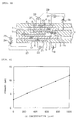
- FIG. 1 is a sectional view showing the configuration of a CO sensor according to the first embodiment of the present invention.
- the CO sensor according to the first embodiment of the present invention includes a first measurement space 2 communicating with a measurement gas atmosphere via a first diffusion-controlling section 1; a second measurement space 4 communicating with the first measurement space 2 via a second diffusion-controlling section 3 filled with a catalyst; a first proton-conductive layer 5; a second proton-conductive layer 6; a first electrode 7 disposed to be in contact with the first proton-conductive layer 5 and to be located within the first measurement space 2; a second electrode 8 disposed to be in contact with the first proton-conductive layer 5 and to be located outside the first measurement space 2; a third electrode 9 disposed to be in contact with the second proton-conductive layer 6 and to be located within the second measurement space 4; a fourth electrode 10 disposed to be in contact with the second proton-conductive layer 6 and to be located outside the second measurement space 4; a heater 14 for heating the second diffusion-controlling section; and a support 11 for supporting the first diffusion-controlling section 1, the first measurement space 2, the second diffusion-control
- the element structure of the CO sensor will be describe in detail.
- the second proton-conductive layer 6 and the second layer of the support 11 define the second measurement space 4; and at the lower side of the support 11, the first proton-conductive layer 5 and the second layer of the support 11 define the first measurement space 2.
- the first diffusion-controlling section 1 and the second diffusion-controlling section 3 are formed in the second layer of the support 11.
- the heater 14 is embedded in the second layer of the support 11 so as to surround the second diffusion-controlling section 3.
- the first electrode 7 and the second electrode 8 face each other while sandwiching the first proton-conductive layer 5.
- the third electrode 9 and the fourth electrode 10 face each other while sandwiching the second proton-conductive layer 6.
- a first opening 12 is formed in the third layer of the support 11; and a second opening 13 is formed in the first layer of the support 11.
- the first opening 12 communicates with the second electrode 8 and the measurement gas atmosphere; and the second opening 13 communicates with the fourth electrode 10 and the measurement gas atmosphere.
- the first and third layers of the support 11 sandwich the second layer of the support 11 to thereby complete the sensor element.
- the first electrode 7 and the second electrode 8 are connected via respective lead portions to a circuit including a first constant-voltage source 15 and a first ammeter 16.
- a first predetermined voltage is applied between the first electrode 7 and the second electrode 8 by means of the first constant-voltage source 15
- current flowing between the first electrode 7 and the second electrode 8 via the first proton-conductive layer 5 can be detected by means of the first ammeter 16.
- the third electrode 9 and the fourth electrode 10 are connected via respective lead portions to a circuit including a second constant-voltage source 17 and a second ammeter 18.
- Each of the proton-conductive layers is formed of a material suitable for operation at relatively low temperature; e.g., Nafion (trademark of Du Pont), which is a fluorine-containing ion-exchange resin film.
- Each of the electrodes is formed of a porous material such as porous carbon and carries a catalyst such as Pt on a side to come into contact with the corresponding proton-conductive layer.
- Each layer of the support is formed of an insulating material; e.g., resin or ceramic such as alumina.
- Each of the diffusion-controlling sections may be formed of porous alumina ceramic having continuous pores, or of a very thin hole.
- the second diffusion-controlling section 3 may be filled with a catalyst which is carried on a porous carrier such as porous carbon or alumina, or filled with powder of the catalyst.
- Physical contact between the electrodes and the corresponding proton-conductive layers may be established through a process of sandwiching the electrodes and the proton-conductive layers by the layers of the support, or a process of bonding the electrodes to the corresponding proton-conductive layers by means of hot-pressing.
- CO contained in the gas under measurement having a controlled hydrogen concentration is reacted with H 2 O in the second diffusion-controlling section 3 in order to produce hydrogen.
- the gas under measurement containing the thus-generated hydrogen is introduced to the second measurement space 4. Due to application of the second predetermined voltage between the third electrode 9 and the fourth electrode 10, current (limiting current of protons) flows between the third electrode 9 and the fourth electrode 10. On the basis of the current (limiting current of protons), a CO concentration of the gas under measurement is obtained.
- the first method through application of a second predetermined voltage between the third electrode and the fourth electrode, hydrogen contained in the gas under measurement introduced into the second measurement space is dissociated, decomposed, or reacted with another element, whereby hydrogen is pumped to the outside of the second measurement space in the form of protons.
- the second predetermined voltage refers to a voltage necessary for causing dissociation, decomposition, or reaction of hydrogen contained in the gas under measurement introduced into the second measurement space and for causing flow of limiting current of protons.
- electromotive force is generated between the third electrode and the fourth electrode in accordance with the difference between the concentration of hydrogen contained in the gas under measurement introduced into the second measurement space (hydrogen concentration at the third electrode) and the hydrogen concentration at the fourth electrode.
- the electromotive force changes in accordance with the amount of hydrogen generated through reaction of CO; i.e., the CO concentration of the gas under measurement. Therefore, the CO concentration of the gas under measurement can be measured on the basis of the electromotive force.
- the concentration of hydrogen contained in the gas under measurement introduced into the second measurement space is controlled through pumping out of hydrogen contained in the gas under measurement at the first measurement space. Therefore, the current flowing between the third electrode and the fourth electrode or the electromotive force generated between the third electrode and the fourth electrode does not depend on the hydrogen concentration of the gas under measurement and depends solely on the CO concentration. Accordingly, the CO sensor according to the present invention enables measurement of CO concentration without being affected by the hydrogen concentration of the gas under measurement.
- a CO sensor according to the second embodiment of the present invention has a first reference electrode.
- the structural and functional features of the CO sensor according to the second embodiment which are similar to those of the CO sensor according to the first embodiment will not be described, and when necessary reference will be made to the description of the first embodiment.
- the elements of the CO sensor according to the second embodiment which have configurations or functions similar to those of the CO sensor according to the first embodiment will be denoted by the same reference numerals, basically. Detailed description will be provided of mainly the features that differ from those of the first embodiment.
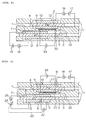
- FIG. 2 is a sectional view showing the configuration of a CO sensor according to the second embodiment of the present invention.
- the CO sensor according to the second embodiment has a first reference electrode 21.
- the first reference electrode 21 is provided to be in contact with the first proton-conductive layer 5 and to be located outside of the first measurement space 2 and the second measurement space 4.
- the first reference electrode 21 is formed so as to reduce influence of variation in hydrogen concentration of a gas under measurement.
- the first electrode 7, the second electrode 8, and the first reference electrode 21 are connected via respective lead portions to a circuit including a first electrometer 22, a first variable-voltage source 24, and a first ammeter 25.
- a sufficiently high voltage (first predetermined voltage) is applied between the first electrode 7 and the second electrode 8 by means of the first variable-voltage source 24, such that a potential difference between the first electrode 7 and the first reference electrode 21, which can be measured by use of the first electrometer 22, assumes a constant value (reference numeral 23 denotes a control signal indicating the potential difference between the first electrode 7 and the first reference electrode 21).
- Reference numeral 23 denotes a control signal indicating the potential difference between the first electrode 7 and the first reference electrode 21.
- Current which flows between the first electrode 7 and the second electrode 8 as a result of application of the first predetermined voltage is measured by means of the first ammeter 25.
- the first reference electrode 21 is preferably composed of a self-generation-type reference electrode, which can be realized as follows. Very small constant current is caused to flow from the first electrode 7 to the first reference electrode 21 (protons are caused to conduct from the first electrode 7 to the first reference electrode 21) in order to generate hydrogen gas in the vicinity of the first reference electrode 21, and a portion of the thus-generated hydrogen gas is caused to leak to the outside via a leak resisting portion (e.g., a very thin hole) of predetermined size formed in the support 11.
- a leak resisting portion e.g., a very thin hole
- the voltage applied between the first electrode 7 and the second electrode 8 can be changed on the basis of the potential difference between the first electrode 7 and the first reference electrode 21. Therefore, voltage applied between the first electrode 7 and the second electrode 8 can be controlled optimally in such a manner that a higher voltage is applied when the resistance between the first electrode 7 and the second electrode 8 increases due to variation in the temperature of the gas under measurement or the temperature of the element itself, and a lower voltage is applied when the resistance between the first electrode 7 and the second electrode 8 decreases. Since the hydrogen concentration on the first electrode 7 can be controlled to a constant level by maintaining constant the potential difference between the first electrode 7 and the first reference electrode 21, the hydrogen concentration in the first measurement space 2 can be controlled more accurately.
- a CO sensor according to the third embodiment of the present invention has a second reference electrode.
- the structural and functional features of the CO sensor according to the third embodiment which are similar to those of the CO sensor according to the second embodiment will not be described, and when necessary reference will be made to the description of the second embodiment.
- the elements of the CO sensor according to the third embodiment which have configurations or functions similar to those of the CO sensor according to the second embodiment will be denoted by the same reference numerals, basically. Detailed description will be provided of mainly the features that differ from those of the second embodiment.
- FIG. 3 is a sectional view showing the configuration of a CO sensor according to the third embodiment of the present invention.
- the CO sensor according to the third embodiment has a second reference electrode 27, as well as the first reference electrode 21.
- the second reference electrode 27 is provided so as to be in contact with the second proton-conductive layer 6 and to be located outside of the first measurement space 2 and the second measurement space 4.
- the second reference electrode 27 is formed so as to reduce influence of variation in hydrogen concentration of a gas under measurement.
- the third electrode 9, the fourth electrode 10, and the second reference electrode 27 are connected via respective lead portions to a circuit including a second electrometer 28, a second variable-voltage source 30, and a second ammeter 31.
- a sufficiently high voltage (second predetermined voltage) is applied between the third electrode 9 and the fourth electrode 10 by means of the second variable-voltage source 30, such that a potential difference between the third electrode 9 and the second reference electrode 27, which can be measured by use of the second electrometer 28, assumes a constant value (reference numeral 29 denotes a control signal indicating the potential difference between the third electrode 9 and the second reference electrode 27).
- Reference numeral 29 denotes a control signal indicating the potential difference between the third electrode 9 and the second reference electrode 27.
- Current which flows between the third electrode 9 and the fourth electrode 10 due to application of the second predetermined voltage is measured by means of the second ammeter 31.
- the second reference electrode 27 is preferably composed of a self-generation-type reference electrode, which can be realized as follows. Very small constant current is caused to flow from the third electrode 9 to the second reference electrode 27 (protons are caused to conduct from the third electrode 9 to the second reference electrode 27) in order to generate hydrogen gas in the vicinity of the second reference electrode 27, and a portion of the thus-generated hydrogen gas is caused to leak to the outside via a leak resisting portion (e.g., a very thin hole) of predetermined size formed in the support 11.
- a leak resisting portion e.g., a very thin hole
- the voltage applied between the third electrode 9 and the fourth electrode 10 can be changed on the basis of the potential difference between the third electrode 9 and the second reference electrode 27. Therefore, the voltage applied between the third electrode 9 and the fourth electrode 10 can be controlled optimally in such a manner that a higher voltage is applied when the resistance between the third electrode 9 and the fourth electrode 10 increases due to variation in the temperature of the gas under measurement or the temperature of the element itself, and a lower voltage is applied when the resistance between the resistance between the third electrode 9 and the fourth electrode 10 decreases. Since the hydrogen concentration on the third electrode 9 can be controlled to a constant level by maintaining constant the potential difference between the third electrode 9 and the second reference electrode 27, CO concentration can be measured more accurately on the basis of the current flowing through the third electrode 9 and the fourth electrode 10.
- FIG. 4 is a graph showing the results of measurement (Measurement Example 1).
- the vertical axis represents current flowing between the third and fourth electrodes
- the horizontal axis represents CO concentration of a gas under measurement (true value).
- the voltage sources were controlled such that a potential difference of 200 mV was generated between the first electrode and the first reference electrode and between the third electrode and the second reference electrode.
- very small constant current was caused to flow from the first electrode to the first reference electrode and from the third electrode to the second reference electrode in order to cause the first and second reference electrodes to operate as self-generation-type reference electrodes.
- the second diffusion-controlling section was heated by the heater to 120°C. Other measurement conditions are shown below.
- the materials used in the CO sensor were:
- the dimensions of the CO sensor were:
- the CO sensor was fabricated by:
- Metal paste containing Pt as a predominant component was screen printed on an alumina green sheet in order to form lead portions and a heater portion thereon.
- Portions of the green sheet were punched out in order to obtain a plurality of green sheets having predetermined shapes, respectively, which were then stacked, bonded together by means of pressure, and fired.
- Diffusion-controlling sections were formed by punching out portions of the formed sheet, or by means of laser machining or the like performed after the firing step.
- Catalyst of the second Diffusion-controlling section was charged into a hole formed in the green sheet and serving as the second diffusion-controlling section and was then fired integrally, or charged into the hole after firing.
- the CO sensor of the present invention enables accurate measurement of CO concentration.
- a CO sensor according to the fourth embodiment of the present invention has a heater for heating the third electrode.
- the structural and functional features of the CO sensor according to the fourth embodiment which are similar to those of the CO sensor according to the first embodiment will not be described, and when necessary reference will be made to the description of the first embodiment.
- the elements of the CO sensor according to the fourth embodiment which have configurations or functions similar to those of the CO sensor according to the first embodiment will be denoted by the same reference numerals, basically. Detailed description will be provided of mainly the features that differ from those of the first embodiment.
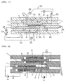
- FIG. 5 is a sectional view showing the configuration of a CO sensor according to the fourth embodiment of the present invention.
- the CO sensor according to the fourth embodiment has an empty through-hole serving as a second diffusion-controlling section 32, and a heater 33 which is embedded in the second layer of the support 11 in the vicinity of the third electrode 9 in order to heat the third electrode 9 (the heater 33 is disposed on the upper side of the second layer of the support 11, on which side the second measurement space 4 is formed). Electrical power is supplied from a heater power source 34 to the heater 33.
- a CO sensor according to the fifth embodiment of the present invention has a first reference electrode (see the second embodiment) and a heater for heating the third electrode (see the fourth embodiment).
- the structural and functional features of the CO sensor according to the fifth embodiment which are similar to those of the CO sensors according to the second and fourth embodiments will not be described, and when necessary reference will be made to the descriptions of the second and fourth embodiments.
- the elements of the CO sensor according to the fifth embodiment which have configurations or functions similar to those of the CO sensors according to the second and fourth embodiments will be denoted by the same reference numerals, basically. Detailed description will be provided of mainly the features that are different from those of the second and fourth embodiments.
- FIG. 6 is a sectional view showing the configuration of a CO sensor according to the fifth embodiment of the present invention.
- the CO sensor according to the fifth embodiment has an empty through-hole serving as a second diffusion-controlling section 32, and a heater 33 which is embedded in the second layer of the support 11 in the vicinity of the third electrode 9 in order to heat the third electrode 9 (the heater 33 is disposed on the upper side of the second layer of the support 11, on which side the second measurement space 4 is formed).
- the CO sensor has a first reference electrode 21 which is provided so as to be in contact with the first proton-conductive layer 5 and to be located outside of the first measurement space 2 and the second measurement space 4.
- the first reference electrode 21 is formed so as to reduce influence of variation in hydrogen concentration of a gas under measurement.
- FIG. 7 is a sectional view showing the configuration of a CO sensor according to the sixth embodiment of the present invention.
- the CO sensor according to the sixth embodiment has a first reference electrode 21 (see the second embodiment), a second reference electrode 27 (see the third embodiment), and a heater 33 for heating the third electrode 9 (see the fourth embodiment). Since these configurations and functions are clearly shown in the descriptions of the second, third, and fourth embodiments, in order to avoid repeated descriptions, reference is made to the descriptions of the second, third, and fourth embodiments rather than describing the structural and functional features of the CO sensor according to the sixth embodiment.
- a CO sensor according to the seventh embodiment of the present invention is of a type such that CO concentration is obtained from electromotive force generated between the third and fourth electrodes (CO sensors according to eight to tenth embodiments are of the same type).
- CO sensors according to eight to tenth embodiments are of the same type.
- the elements of the CO sensor according to the seventh embodiment which have configurations or functions similar to those of the CO sensor according to the first embodiment will be denoted by the same reference numerals, basically. Detailed description will be provided of mainly the features that differ from those of the first embodiment.
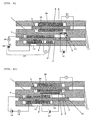
- FIG. 8 is a sectional view showing the configuration of a CO sensor according to the seventh embodiment of the present invention.
- the CO sensor according to the seventh embodiment has a fourth electrode 36 which is formed in such a manner that influence of variation in hydrogen concentration of a gas under measurement can be reduced.
- a third electrode 35 and the fourth electrode 36 are connected to a first electrometer 37 via respective lead portions in order to measure electromotive force generated between the third electrode 35 and the fourth electrode 36 via the second proton-conductive layer 6.
- a method of measuring CO concentration by use of the above-described CO sensor will be described.
- hydrogen contained in a gas under measurement which has been introduced into the first measurement space 2 via the first diffusion-controlling section 1 is dissociated, decomposed, or reacted with another element in order to generate protons.
- the thus-generated protons are moved from the first electrode 7 to the second electrode 8 via the first proton-conductive layer 5, or protons are moved from the second electrode 8 to the first electrode 7 via the first proton-conductive layer 5 (when the hydrogen concentration of the measurement gas is extremely low), so that the hydrogen concentration within the first measurement space 2 is controlled to a constant level.
- CO contained in the gas under measurement having a controlled hydrogen concentration is reacted with H 2 O in the second diffusion-controlling section 3 in order to produce hydrogen.
- the gas under measurement containing the thus-generated hydrogen is introduced to the second measurement space 4.
- the electromotive force generated between the third electrode 35 and the fourth electrode 36 changes in accordance with the concentration of the generated hydrogen. Therefore, the CO concentration of the gas under measurement can be obtained on the basis of the electromotive force generated between the third electrode 35 and the fourth electrode 36.
- FIG. 9 is a sectional view showing the configuration of a CO sensor according to the eighth embodiment of the present invention.
- the CO sensor according to the eighth embodiment has a first reference electrode 21 (see the second embodiment) in addition to the structural elements of the CO sensor according to the seventh embodiment.
- the configuration and function of the reference electrode 21 are clearly shown in the description of the second embodiment, and the method of measuring CO concentration by use of the CO sensor according to the eighth embodiment is clearly shown in the description of the seventh embodiment. Therefore, in order to avoid repeated descriptions, reference is made to the descriptions of the second and seventh embodiments rather than providing a description of the eighth embodiment.
- FIG. 10 is a sectional view showing the configuration of a CO sensor according to the ninth embodiment of the present invention.
- the CO sensor according to the ninth embodiment differs from the CO sensor according to the seventh embodiment in that the CO sensor of the present embodiment has a heater 33 for heating the third electrode 35 (see the fourth embodiment).
- the configuration and function of the heater 33 are clearly shown in the description of the fourth embodiment, and the method of measuring CO concentration by use of the CO sensor according to the eighth embodiment is clearly shown in the description of the seventh embodiment. Therefore, in order to avoid repeated descriptions, reference is made to the descriptions of the fourth and seventh embodiments rather than providing a description of the ninth embodiment.
- FIG. 11 is a sectional view showing the configuration of a CO sensor according to the tenth embodiment of the present invention.
- the CO sensor according to the tenth embodiment differs from the CO sensor according to the seventh embodiment in that the CO sensor of the present embodiment has a first reference electrode 21 (see the second embodiment) and a heater 33 for heating the third electrode 35 (see the fourth embodiment).
- the configurations and functions of these additional elements are clearly shown in the descriptions of the second and fourth embodiments, and the method of measuring CO concentration by use of the CO sensor according to the tenth embodiment is clearly shown in the description of the seventh embodiment. Therefore, in order to avoid repeated descriptions, reference is made to the descriptions of the second, fourth, and seventh embodiments rather than providing a description of the tenth embodiment.
- the CO sensor according to the eleventh embodiment differs from the CO sensors according to the first through tenth embodiments in that the first and second proton-conductive layers are replaced with a common proton-conductive layer, and measurement spaces, electrodes, etc. are disposed symmetrically.
- the configurations and functions of elements of the CO sensor according to the eleventh embodiment which are identical with those of the CO sensors according to the first through tenth embodiments, reference can be made to the corresponding portions of the descriptions of the first through tenth embodiments (e.g., with regard to the measurement method, see the first embodiment). Description will be provided of mainly the feature of the CO sensor of the eleventh embodiment which differ from those of the first through tenth embodiments.
- FIG. 12 is a sectional view showing the configuration of a CO sensor according to the eleventh embodiment of the present invention.
- a first measurement space 2 is formed within a support 11 to be located at one side
- a second measurement space 4 is formed within the support 11 to be located at the other side.
- the first measurement space 2 communicates with a measurement gas atmosphere via a first diffusion-controlling section 1.
- the second measurement space 4 communicates with the first measurement space 2 via a second diffusion-controlling section 3.
- a heater 41 is embedded in the support 11 in the vicinity of the second diffusion-controlling section 3 and receives electrical power from a heater power source 42. Further, a proton-conductive layer 40 is supported within the support 11.
- First and second electrodes 7 and 8 are disposed at a lefthand portion of the proton-conductive layer 40, and third and fourth electrodes 9 and 10 are disposed at a right-hand portion of the proton-conductive layer 40.
- the first and second electrodes 7 and 8 face each other via the proton-conductive layer 40; and the third and fourth electrodes 9 and 10 face each other via the proton-conductive layer 40.
- the second electrode 8 communicates with the outside via an opening 12a; and the fourth electrode 10 communicates with the outside via an opening 12b.
- the CO sensor of the eleventh embodiment is configured in such a manner that hydrogen gas concentration is measured on the basis of proton current flowing between the third electrode 9 and the fourth electrode 10.
- the CO sensor of the eleventh embodiment is configured in such a manner that hydrogen gas concentration is measured on the basis of electromotive force (generated due to difference in hydrogen gas concentration) generated between the third electrode 9 and the fourth electrode 10.
Landscapes
- Chemical & Material Sciences (AREA)
- Life Sciences & Earth Sciences (AREA)
- Health & Medical Sciences (AREA)
- Pathology (AREA)
- General Physics & Mathematics (AREA)
- Engineering & Computer Science (AREA)
- Physics & Mathematics (AREA)
- Analytical Chemistry (AREA)
- Biochemistry (AREA)
- General Health & Medical Sciences (AREA)
- Immunology (AREA)
- Chemical Kinetics & Catalysis (AREA)
- Molecular Biology (AREA)
- Electrochemistry (AREA)
- Combustion & Propulsion (AREA)
- Food Science & Technology (AREA)
- Medicinal Chemistry (AREA)
- Measuring Oxygen Concentration In Cells (AREA)
Applications Claiming Priority (2)
| Application Number | Priority Date | Filing Date | Title |
|---|---|---|---|
| JP2001000734 | 2001-01-05 | ||
| JP2001000734A JP2002207024A (ja) | 2001-01-05 | 2001-01-05 | Coセンサ及びco濃度測定方法 |
Publications (2)
| Publication Number | Publication Date |
|---|---|
| EP1221610A2 true EP1221610A2 (de) | 2002-07-10 |
| EP1221610A3 EP1221610A3 (de) | 2005-05-04 |
Family
ID=18869468
Family Applications (1)
| Application Number | Title | Priority Date | Filing Date |
|---|---|---|---|
| EP02250041A Withdrawn EP1221610A3 (de) | 2001-01-05 | 2002-01-04 | CO-Sensor und Verfahren zum Messen des CO-Gehaltes |
Country Status (4)
| Country | Link |
|---|---|
| US (1) | US6797151B2 (de) |
| EP (1) | EP1221610A3 (de) |
| JP (1) | JP2002207024A (de) |
| CA (1) | CA2366638A1 (de) |
Families Citing this family (9)
| Publication number | Priority date | Publication date | Assignee | Title |
|---|---|---|---|---|
| DE10227012A1 (de) * | 2002-06-18 | 2004-01-15 | Robert Bosch Gmbh | Sensorelement für einen Messfühler zur Bestimmung der Sauerstoffkonzentration im Abgas von Brennkraftmaschinen |
| JP6523144B2 (ja) * | 2015-11-17 | 2019-05-29 | 日本碍子株式会社 | ガスセンサ |
| US10515907B2 (en) | 2018-05-17 | 2019-12-24 | Sandisk Technologies Llc | Three-dimensional memory device containing hydrogen diffusion blocking structures and method of making the same |
| US10515897B2 (en) | 2018-05-17 | 2019-12-24 | Sandisk Technologies Llc | Three-dimensional memory device containing hydrogen diffusion blocking structures and method of making the same |
| EP3835774B1 (de) * | 2018-08-10 | 2024-07-31 | TDK Corporation | Gassensor |
| US12111281B2 (en) | 2018-11-21 | 2024-10-08 | Hyaxiom, Inc. | Hydrogen concentration sensor |
| US11824238B2 (en) | 2019-04-30 | 2023-11-21 | Hyaxiom, Inc. | System for managing hydrogen utilization in a fuel cell power plant |
| US12000794B2 (en) * | 2020-12-08 | 2024-06-04 | Hyaxiom, Inc. | Hydrogen concentration sensor |
| US11768186B2 (en) * | 2020-12-08 | 2023-09-26 | Hyaxiom, Inc. | Hydrogen concentration sensor |
Citations (2)
| Publication number | Priority date | Publication date | Assignee | Title |
|---|---|---|---|---|
| EP0731351A2 (de) * | 1995-03-09 | 1996-09-11 | Ngk Insulators, Ltd. | Verfahren und Vorrichtung zur Messung von einer brennbaren Gaskomponente durch Verbrennung des Komponentes |
| EP0911629A1 (de) * | 1997-10-24 | 1999-04-28 | General Motors Corporation | Brenstoffzelle - CO Sensor |
Family Cites Families (4)
| Publication number | Priority date | Publication date | Assignee | Title |
|---|---|---|---|---|
| US5302274A (en) * | 1990-04-16 | 1994-04-12 | Minitech Co. | Electrochemical gas sensor cells using three dimensional sensing electrodes |
| JP3453954B2 (ja) * | 1994-11-02 | 2003-10-06 | トヨタ自動車株式会社 | 一酸化炭素検出装置、有機化合物検出装置および低級アルコール検出装置 |
| JPH1114589A (ja) * | 1997-06-23 | 1999-01-22 | Ngk Insulators Ltd | ガスセンサ |
| KR100319947B1 (ko) * | 1998-04-06 | 2002-01-09 | 마츠시타 덴끼 산교 가부시키가이샤 | 탄화수소 센서 |
-
2001
- 2001-01-05 JP JP2001000734A patent/JP2002207024A/ja not_active Withdrawn
-
2002
- 2002-01-04 EP EP02250041A patent/EP1221610A3/de not_active Withdrawn
- 2002-01-04 CA CA002366638A patent/CA2366638A1/en not_active Abandoned
- 2002-01-04 US US10/035,248 patent/US6797151B2/en not_active Expired - Fee Related
Patent Citations (2)
| Publication number | Priority date | Publication date | Assignee | Title |
|---|---|---|---|---|
| EP0731351A2 (de) * | 1995-03-09 | 1996-09-11 | Ngk Insulators, Ltd. | Verfahren und Vorrichtung zur Messung von einer brennbaren Gaskomponente durch Verbrennung des Komponentes |
| EP0911629A1 (de) * | 1997-10-24 | 1999-04-28 | General Motors Corporation | Brenstoffzelle - CO Sensor |
Also Published As
| Publication number | Publication date |
|---|---|
| EP1221610A3 (de) | 2005-05-04 |
| US20020092780A1 (en) | 2002-07-18 |
| CA2366638A1 (en) | 2002-07-05 |
| JP2002207024A (ja) | 2002-07-26 |
| US6797151B2 (en) | 2004-09-28 |
Similar Documents
| Publication | Publication Date | Title |
|---|---|---|
| JP3544437B2 (ja) | ガスセンサ | |
| EP1037041B1 (de) | Gassensor | |
| EP1103807B1 (de) | Wasserstoffgassensor | |
| JPH0810211B2 (ja) | ガスセンサ及びその製造法 | |
| WO1996024052A9 (en) | Electrochemical gas sensor | |
| WO1996024052A1 (en) | Electrochemical gas sensor | |
| CN109997034B (zh) | 用于电化学传感器中的电解质浓度测量的方法和设备 | |
| US7189364B2 (en) | Hydrogen sensor | |
| US20100326825A1 (en) | Solid ion conductor, electrochemical device using a solid ion conductor, and process for producing the same | |
| CN114778647B (zh) | 电解质浓度测量的方法和设备 | |
| EP1221610A2 (de) | CO-Sensor und Verfahren zum Messen des CO-Gehaltes | |
| US7306712B2 (en) | Gas sensor and method for measuring gas concentration using the same | |
| CN109661571B (zh) | 用于识别及清洁电化学传感器的污染的系统和方法 | |
| US6764582B2 (en) | Hydrogen sensor | |
| Korotcenkov et al. | Electrochemical gas sensors: fundamentals, fabrication, and parameters | |
| KR20100036726A (ko) | 질소산화물 가스센서 | |
| JPWO2011145150A1 (ja) | 水素ガスセンサー | |
| EP1288658A2 (de) | Gassensor mit protonenleitender Schicht | |
| JP2003207483A (ja) | ガスセンサ | |
| EP1288655A2 (de) | Gassensor | |
| JP2004117123A (ja) | ガスセンサ | |
| KR20250138463A (ko) | 전류 측정식 고농도 수소 가스 센서 및 이의 제조방법 | |
| JP2003149191A (ja) | ガスセンサ | |
| JP2003075404A (ja) | ガスセンサ |
Legal Events
| Date | Code | Title | Description |
|---|---|---|---|
| PUAI | Public reference made under article 153(3) epc to a published international application that has entered the european phase |
Free format text: ORIGINAL CODE: 0009012 |
|
| AK | Designated contracting states |
Kind code of ref document: A2 Designated state(s): AT BE CH CY DE DK ES FI FR GB GR IE IT LI LU MC NL PT SE TR |
|
| AX | Request for extension of the european patent |
Free format text: AL;LT;LV;MK;RO;SI |
|
| PUAL | Search report despatched |
Free format text: ORIGINAL CODE: 0009013 |
|
| AK | Designated contracting states |
Kind code of ref document: A3 Designated state(s): AT BE CH CY DE DK ES FI FR GB GR IE IT LI LU MC NL PT SE TR |
|
| AX | Request for extension of the european patent |
Extension state: AL LT LV MK RO SI |
|
| RIC1 | Information provided on ipc code assigned before grant |
Ipc: 7G 01N 27/419 B Ipc: 7G 01N 33/00 B Ipc: 7G 01N 27/407 A |
|
| 17P | Request for examination filed |
Effective date: 20050912 |
|
| AKX | Designation fees paid |
Designated state(s): DE |
|
| 17Q | First examination report despatched |
Effective date: 20090205 |
|
| STAA | Information on the status of an ep patent application or granted ep patent |
Free format text: STATUS: THE APPLICATION IS DEEMED TO BE WITHDRAWN |
|
| 18D | Application deemed to be withdrawn |
Effective date: 20090616 |