EP1224740B1 - Procede et dispositif pour coder un turbo-code perfore - Google Patents
Procede et dispositif pour coder un turbo-code perfore Download PDFInfo
- Publication number
- EP1224740B1 EP1224740B1 EP99957950A EP99957950A EP1224740B1 EP 1224740 B1 EP1224740 B1 EP 1224740B1 EP 99957950 A EP99957950 A EP 99957950A EP 99957950 A EP99957950 A EP 99957950A EP 1224740 B1 EP1224740 B1 EP 1224740B1
- Authority
- EP
- European Patent Office
- Prior art keywords
- data
- puncturing
- data stream
- interleaving
- coded
- Prior art date
- Legal status (The legal status is an assumption and is not a legal conclusion. Google has not performed a legal analysis and makes no representation as to the accuracy of the status listed.)
- Expired - Lifetime
Links
- 238000000034 method Methods 0.000 title claims description 15
- 230000005540 biological transmission Effects 0.000 claims abstract description 36
- 230000009897 systematic effect Effects 0.000 claims description 20
- 230000015654 memory Effects 0.000 claims description 13
- 238000013507 mapping Methods 0.000 description 6
- 239000011159 matrix material Substances 0.000 description 3
- 230000008878 coupling Effects 0.000 description 1
- 238000010168 coupling process Methods 0.000 description 1
- 238000005859 coupling reaction Methods 0.000 description 1
- 230000003247 decreasing effect Effects 0.000 description 1
Images


Classifications
-
- H—ELECTRICITY
- H04—ELECTRIC COMMUNICATION TECHNIQUE
- H04L—TRANSMISSION OF DIGITAL INFORMATION, e.g. TELEGRAPHIC COMMUNICATION
- H04L1/00—Arrangements for detecting or preventing errors in the information received
- H04L1/004—Arrangements for detecting or preventing errors in the information received by using forward error control
- H04L1/0056—Systems characterized by the type of code used
- H04L1/0067—Rate matching
- H04L1/0068—Rate matching by puncturing
- H04L1/0069—Puncturing patterns
-
- H—ELECTRICITY
- H03—ELECTRONIC CIRCUITRY
- H03M—CODING; DECODING; CODE CONVERSION IN GENERAL
- H03M13/00—Coding, decoding or code conversion, for error detection or error correction; Coding theory basic assumptions; Coding bounds; Error probability evaluation methods; Channel models; Simulation or testing of codes
- H03M13/29—Coding, decoding or code conversion, for error detection or error correction; Coding theory basic assumptions; Coding bounds; Error probability evaluation methods; Channel models; Simulation or testing of codes combining two or more codes or code structures, e.g. product codes, generalised product codes, concatenated codes, inner and outer codes
- H03M13/2957—Turbo codes and decoding
-
- H—ELECTRICITY
- H04—ELECTRIC COMMUNICATION TECHNIQUE
- H04L—TRANSMISSION OF DIGITAL INFORMATION, e.g. TELEGRAPHIC COMMUNICATION
- H04L1/00—Arrangements for detecting or preventing errors in the information received
- H04L1/004—Arrangements for detecting or preventing errors in the information received by using forward error control
- H04L1/0056—Systems characterized by the type of code used
- H04L1/0071—Use of interleaving
-
- H—ELECTRICITY
- H04—ELECTRIC COMMUNICATION TECHNIQUE
- H04L—TRANSMISSION OF DIGITAL INFORMATION, e.g. TELEGRAPHIC COMMUNICATION
- H04L1/00—Arrangements for detecting or preventing errors in the information received
- H04L1/004—Arrangements for detecting or preventing errors in the information received by using forward error control
- H04L1/0056—Systems characterized by the type of code used
- H04L1/007—Unequal error protection
Definitions
- the invention relates to a coding method and Coding device for coding a serial data stream with so-called turbo codes.
- the coding adjusts the data stream from an information data source to a transmission system to increase the security of information transmission against disturbances.
- the Transmission channel exposed to particularly strong interference is the so-called turbo encoder, which is particularly useful for coding of data to be transmitted in the field of mobile radio.
- Turbo encoders are binary chained encoders, which consist of several linked encoders. there one distinguishes serially concatenated turbo encoders as well Turbo encoders linked in parallel.
- Fig. 1 shows the structure of a series-linked turbo coding device According to the state of the art.
- One by one Serial data stream originating from information data source d is a data reader for reading the data d fed, which reads the data and data frames coded predetermined length.
- the data frames or data blocks arrive in a first encoder A, each date within the data frame corresponding to one Coding instruction encoded and the encoded data as a code data block C1 delivers to an interleaving circuit.
- the Interleaving circuit scrambles the encoded data block C1 according to an interleaving assignment rule, which is stored in the interleaving circuit.
- the Nesting assignment rule or permutation matrix assigns each data point within the code data block C1 a particular other data point too.
- the code data block consists of five Bits, for example, by the interleaving circuit the date at the first position of the coded data block C1 the first position of the nested code data block C1 ' assigned while, for example, that in the second position of the code data block C1 located data bit to the third position of the interleaved code output data block C1 ' becomes.
- Table 1 shows an example of an interleaving assignment, in which an output data sequence is generated from an input data sequence in accordance with the interleaving assignment specification.
- Input data sequence x 1 x 2 x 3 x 4 x 5 Output data sequence x 1 x 3 x 4 x 5 x 2
- the interleaved coded data block C1 ' is connected downstream Encoder B fed to re-encoding to a coded data block C2.
- the encoded data block C2 is also through an interleaving circuit nested and via a modulation device delivered an antenna for data transmission.
- the encoder A is also referred to as the outer encoder while the encoder B is called the inner encoder.
- the encoder A, the interleaving circuit or interleaving circuit Il and the encoder B form the actual data channel encoder.
- the second group of turbo encoders namely the encoders linked in parallel, is also systematically encoded.
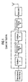
- Fig. 2 shows the structure of a parallel-linked turbo encoder according to the prior art.
- a serial data stream with serial data d originating from an information data source is read in by a data read-in device and combined into data blocks X in groups.
- Each data block X consists of several data bits x i .
- the data read-in device is connected to a first input of a multiplexer via a line L1.
- the output of the data reading device is connected via a line L2 to the input of a first encoder A, which codes the data block X in accordance with a coding rule to form a coded data block C 1 and delivers it to a puncturing device.
- the data block X output at the output of the data reading device via a line L3 is interleaved or rearranged by an interleaving circuit I in accordance with a predetermined permutation matrix.
- the interleaved data block I (X) is fed to a second encoder B, which encodes the interleaved data block I (X) according to an encoding rule to form a code data block C 2 .
- the coded data block C 2 is also fed to the puncturing device P.
- the puncturing device P links the coded data block C 1 and the coded data block C 2 each with an associated puncturing data field.
- the puncturing by the puncturing device P is carried out in order to increase the data transmission rate.
- the punctured coded data block P (C 1 ) and the punctured data block P (C 2 ) are applied to inputs of the multiplexer, which the read data block X and the two punctured data blocks P (C 1 ) and P (C 2 ) to a transmission data block S time-multiplexed.
- the encoder A encodes the read-in data block X in accordance with a coding rule to form a code data block C 1 :
- C 1 (c 11 , c 12 , c 13 , c 14 , c 15 )
- the interleaving circuit I interleaves the read data block X, for example in accordance with the following interleaving assignment: Entrance X Output I (x) x 1 x 1 x 2 x 3 x 3 x 4 x 4 x 5 x 5 x 2
- the interleaved or interleaved data block I (x) is fed to the encoder B, which encodes the interleaved data block according to an encoding rule to form an encoded data block C 2 :
- C 2 (c 21 , c 22 , c 23 , c 24 , c 25 )
- the puncturing device P punctures the data block C 1 coded by the encoder A and the data block C 2 coded by the encoder B, each with an associated puncturing data field.
- the multiplexer Mux multiplexes the read-in data block X and the two punctured and coded data blocks P (C 1 ), P (C 2 ) delivered by the puncturing device P to form a transmission data block S.
- X (x 1 , x 2 , x 3 , x 4 , x 5 )
- P (C 1 ) (c 11 , 0, c 13 , 0, c 15 )
- P (C 2 ) (0, c 22 , 0, c 24 , 0)
- S (x 1 , c 11 , x 2 , c 22 , x 3 , c 13 , x 4 , c 24 , x 5 , c 15 )
- the transmission data block S contains on the one hand a systematic coding information content, since the originally read in data x 1 , x 2 , x 3 , x 4 , x 5 are contained in the transmission data block S, and on the other hand the transmission data block S contains a non-systematic information content due to the coded Data c.
- the parallel-linked turbo coding device according to the prior art shown in FIG. 2, however, has the disadvantage that an associated, non-systematic coded data bit c is not sent as non-systematic information content to each original data bit of the read data block X. following table can be seen:
- the coded data bits c 11 , c 22 , c 13 , c 24 , c 15 contained in the transmission data block S which form the non-systematic information content of the transmission data block S, represent coded data bits of the original data bits x 1 , x 3 , x 3 , x 5 as well as x 5.
- no coded data bits c are contained in the transmission data block S.
- the original data bits x 2 , x 4 are only transmitted systematically.
- the non-systematic information content of the transmit data block S is lower than in a case in which a corresponding coded data bit c is transmitted for each information data bit x. Accordingly, the bit-error ratio BFV increases with decreasing non-systematic information content within the transmission data block S.
- this object is achieved by a coding method with the features specified in the claim and by a coding device with the specified in claim 6 Features resolved.
- the serial data stream emitted by the data source is preferably read in blocks for coding.
- the nesting assignment for nesting the puncturing data field read from the associated interleaving circuit.
- the nesting mapping is preferably set.
- the puncturing takes place by logically linking a data stream to a Puncturing data field by means of a logic circuit.
- the invention also provides a coding device for Coding of a serial data stream with a data input for creating the from a sequence of Data bits existing serial data stream;
- At least one encoder connected to the data input for encoding the data stream into an encoded data stream; at least one connected to the data input Interleaving circuit for interleaving the data stream to a nesting data stream corresponding to one Nesting mapping where the Nesting stream through one of the Interleaving circuits downstream encoder encoding an encoded interleaving data stream; a puncturing device for puncturing the coded Data stream and the encoded interleaving data stream by means of a respective puncturing circuit for linking the Data stream to be punctured with a puncturing data field Data streams, wherein the puncturing device is a puncturing interleaving circuit which has the puncturing data field for puncturing the encoded interleaving data stream according to the associated nesting mapping nested and to the puncturing circuit to link with delivers the encoded interleaving data stream; and with a multiplexer for multiplexing the serial Data stream and that delivered by the puncturing device punctured data streams to a broadcast data stream, where each data bit of the data stream applied to the data
- the coding device is the puncture interleaving circuit with the associated interleaving circuit via a Readout line for reading out the nesting assignment connected.
- the interleaving circuits preferably each have a memory for storing the Nesting assignments.
- the Nesting mapping in the nesting circuits each adjustable via a setting line.
- the puncturing data fields are each in The puncturing device can be saved.
- the puncturing data fields are preferably each over Adjustment lines adjustable.
- the puncturing circuit is preferably a logic circuit for the logical connection of the data stream with the puncturing data field.
- the puncturing data field contains several data elements, each a logical one assume a high H state or a logically low L state.
- the coding device has a preferred Embodiment a data reading device on the serial data stream at the data input for Reads in data blocks of a certain length.
- the length of the data blocks is preferably adjustable.
- the encoders are recursive systematic convolutional encoder.
- the coding device according to the invention shown in FIG. 3 1 for coding a serial data stream has a data input 2 on which one from an information data source serial data stream is present.
- the serial data stream is via a line 3 of a data reader 4 fed, which reads the serial data and grouped into data blocks.
- the length of the data blocks or data frame can be set via a setting line 5.
- the signal output 6 of the data reader 4 gives the data blocks via a line 7 to a first signal input 8 of a multiplexer 9.
- the data blocks on Signal output 6 of the data reader 4 are also via internal lines 10, 11 to a first encoder 12 Coding supplied with a first predetermined coding specification.
- the encoder 16 encodes the nested data stream present on line 15 or the corresponding nested data block accordingly a predetermined coding rule for a coded interleaving data stream, which is delivered via a line 17 becomes.
- the data stream encoded by the encoder 12 is via a Output line 18 a first signal input 19 of a puncturing device 20 fed.
- the puncturing device 20 has a further signal input 21 which is connected to the output line 17 of encoder 16 for receiving the encoded interleaving data stream connected.
- the puncturing device 20 contains a first puncturing circuit 22, whose input 23 via a signal line 24 the signal line connection 19 of the puncturing device 20 connected is.
- the puncturing circuit 22 punctures that of the coded data stream received with the encoder 12 with a Puncturing data field, which is stored in a first memory 25 Puncturing device 20 is stored.
- the puncturing circuit 22 links this in the puncture data field memory 25 stored puncturing data field by the puncturing data field via a line 26 from the memory 25 reads out and bit by bit using a logic circuit logically linked to the coded data stream at signal input 23.
- the one stored in the puncturing data field memory 25 Puncturing data field has several data elements, each a logic high or logic take low L state.
- the in the puncturing data field Data elements contained are preferably in a logical AND operation with that at signal input 23 adjacent coded data stream linked bit by bit. For this each data bit of the data block present at signal input 23 or data frame with a corresponding data element of the puncturing data field logically AND-linked.
- the puncturing of the encoded data stream by the puncturing circuit 22 serves to increase the transmission bit rate.
- the punctured coded data stream is sent to a signal output 27 of the puncturing circuit 22 is output and is via a line 28 to a second signal input 29 of the multiplexer 9 created.
- the applied to the signal input 21 of the puncturing device 20 encoded nesting data stream is through an internal Line 30 to a signal input 31 of a second in the puncturing device 20 contained puncturing circuit 32 fed. That in a second puncturing data field memory 33 of the puncturing device 20 Puncturing data field is connected via line 34 to a puncturing interleaving circuit 35 read and there with a nesting assignment nested or rearranged, that with that interleaving assignment of the interleaving circuit 14 is identical. This is the interleaving circuit 35 preferably via a readout line 36 with the interleaving circuit 14 for reading out the associated nesting mapping.
- the in the Interleaving circuit 35 of the puncturing device 20 interleaving assignment rule read in via the read line 36 is stored in the puncture data field memory stored puncturing data field applied and comes across as a nested puncture data field a line 37 to the puncturing circuit 32, which the on Coded interleaving data stream applied to signal input 31 logical with the nested puncturing data field for delivering a punctured coded interleaving data stream to a signal output 38 of the puncturing circuit 32 connected.
- the coded and by the puncturing circuit 32 punctured nesting data stream arrives via a Line 39 to a third signal input 40 of the multiplexer 9th
- the ones stored in the two puncturing data field memories 25, 33 Puncturing data fields are preferably over Adjustment lines 41, 42 adjustable. Furthermore, preferred embodiment, the nesting mapping via a setting line 43 in the interleaving circuit 14 entered.
- the multiplexer 9 multiplexes those at the signal inputs 8, 29, 40 data streams, i.e. the on Signal input 8 serial data stream present at the signal input 29 encoded and by the puncturing circuit 22 punctured serial data stream as well as the am Signal input 40 adjacent, coded nested and serial data stream punctured by the puncturing circuit 32, so that a at the signal output 44 of the multiplexer 9 Transmitted data stream S is emitted via a signal line 45.
- the non-systematic information content is in the 3 coding device according to the invention shown maximum, so that the bit error ratio when transmitting the transmission data stream S becomes minimal over a transmission channel.
- a data block X consisting of five bits is read in by the data reading device 4.
- X (x 1 , x 2 , x 3 , x 4 , x 5 )
- the read-in data block X is coded by the encoder 12 by a predetermined coding rule to form a coded data block C 1 .
- C 1 (c 11 , c 12 , c 13 c 14 , c 15 )
- the data block X is interleaved or interleaved by the interleaving circuit 14 in accordance with an interleaving assignment.
- Entrance X Output I (x) x 1 x 1 x 2 x 3 x 3 x 4 x 4 x 5 x 5 x 2
- the encoder 16 encodes the data block interleaved by the interleaving circuit in accordance with the interleaving assignment in accordance with a predetermined coding rule to form an encoded interleaved data block C 2 .
- C 2 (c 21 , c 22 , c 23 , c 24 , c 25 )
- a first puncturing data field P 1 is stored in the puncturing data field memory 25.
- P 1 (10101)
- a second puncturing data field P 2 is stored in the puncturing data field memory 33.
- P 2 (01010)
- the interleaving circuit 35 reads out the interleaving assignment temporarily stored in the interleaving circuit 14 and interleaves the data elements of the puncturing data field stored in the puncturing data field memory 33 in accordance with this interleaving assignment to form an interleaved puncturing data field I (P 2 ).
- P 2 I (P 2 ) 0 0 1 0 0 1 1 0 0 1
- the multiplexer 9 multiplexes the three serial data present at the signal inputs 8, 29, 40 into a transmission data stream S.
- S x 1 , c 11 , x 2 , x 3 , c 13 , c 23 , x 4 , x 5 , c 15 , c 25
- a coded data bit c is transmitted as the non-systematic coding content of the transmission data stream.
- the coded data bit c 11 from the original data bit x 1 , the coded data bit c 13 from the original data bit x 3 , the coded data bit c 23 from the original data bit x 4 , the coded data bit c 15 from the original data bit x 5 and the coded data bit c 25 is generated from the original data bit x 2 .
- the non-systematic coding content of the transmission data block S is thus maximum, as a result of which the bit error ratio during transmissions of the transmission data block S via a transmission channel is minimal.
- the maximization of the non-systematic coding content within the transmission data block is achieved by coupling the puncturing device 20 to the interleaving circuit 14, from which the interleaving assignment is read out via the line 36 for interleaving the puncturing data field P 2 .
- the puncturing of the serial data stream can be different for different data bit sequences of the data stream.
- the data stream received by the data source is read in blocks for further coding.
- the read data block X can have several successive data sequences X 1 , X 2 with different meaning or importance.
- a first data sequence X 1 of the read data block X contains, for example, information which is of greater importance in comparison with the information of a further data sequence X 2 of the read data block X.
- the data bits of the data sequence X 1 are therefore preferably protected with a lower code rate than the less significant data bits of the data sequence X 2 of the read-in data block X. This is achieved with a puncturing data field P which contains a first puncturing data element sequence P.
- the data bits of the first data sequence X 1 of the read-in data block X are thus not punctured by the first puncturing data element sequence P a of the puncturing data field P, which together with the systematic bits results in a code rate of 1/3 for these important data bits.
- the alternating puncturing of the subsequent data sequence X 2 of the data block X by means of the second puncturing data element sequence P b means that exactly one non-systematic bit is transmitted together with one systematic bit, so that a code rate of 1 ⁇ 2 results.
- the unequal error protection is thus in terms of circuitry guaranteed very simple way.
- the uneven Error protection in the coding device according to the invention particularly flexible, since the in the puncturing data fields 25, 33 stored puncturing data fields P via the setting lines 41, 42 according to a known one Data sequence format of the serial data stream flexible are adjustable.
Landscapes
- Engineering & Computer Science (AREA)
- Computer Networks & Wireless Communication (AREA)
- Signal Processing (AREA)
- Physics & Mathematics (AREA)
- Probability & Statistics with Applications (AREA)
- Theoretical Computer Science (AREA)
- Error Detection And Correction (AREA)
- Reduction Or Emphasis Of Bandwidth Of Signals (AREA)
Claims (18)
- Procédé de codage pour coder un flux de données en série avec les étapes suivantes :(a) codage d'un flux de données (X) provenant d'une source de données, constituée d'une suite de bits de données (xi), à l'aide d'un codeur (12) en flux de données codés ;(b) entrelacement du flux de données provenant de la source de données (X) selon des allocations d'entrelacement (I) prédéterminées en flux de données d'entrelacement à l'aide de circuits d'entrelacement (14) ;(c) codage des flux de données d'entrelacement à l'aide de codeurs (16) correspondants en flux de données d'entrelacement codé ;(d) ponctuation des flux de données codés et des flux de données d'entrelacement codé par combinaison avec des champs de données de ponctuation (P1, P2) associés prédéterminés, le champ de données de ponctuation (P2), pour la ponctuation d'un flux de données d'entrelacement codé, étant entrelacé avant la combinaison selon l'allocation d'entrelacement (I) avec la quelle le flux de données d'entrelacement codé est entrelacé, le procédé de codage étant caractérisé par(e) le multiplexage du flux de données généré par la source de données et des flux de données ponctués en un flux de données d'émission, un bit de données codé étant transmis en tant que contenu de codage non systématique du flux de données d'émission pour chaque bit de données (x) du flux de données reçu.
- Procédé de codage selon la revendication 1, caractérisé en ce que le flux de données (X) provenant de la source de données est entré en blocs pour un codage ultérieur.
- Procédé de codage selon la revendication 1 ou 2, caractérisé en ce que l'allocation d'entrelacement (I) est extraite du circuit d'entrelacement (14) associé pour l'entrelacement du champ de données de ponctuation (P).
- Procédé de codage selon l'une des revendications précédentes, caractérisé en ce que l'allocation d'entrelacement (I) peut être ajustée.
- Procédé de codage selon l'une des revendications précédentes, caractérisé en ce que la ponctuation est réalisé par combinaison logique d'un flux de données avec un champ de données de ponctuation (P) à l'aide d'un circuit logique.
- Dispositif de codage pour coder un flux de données en série comprenant :(a) une entrée de données (2) pour entrer le flux de données constitué d'une suite de bits de données ;(b) au moins un codeur (12) relié à l'entrée de données (2) pour le codage du flux de données en un flux de données codé ;(c) au moins un circuit d'entrelacement (14) relié à l'entrée de données (2) pour l'entrelacement du flux de données en un flux de données d'entrelacement selon une allocation d'entrelacement, le flux de données d'entrelacement étant codé par un codeur (16), branché en aval du circuit d'entrelacement (14), en un flux de données d'entrelacement codé ;(d) un dispositif de ponctuation (20) pour ponctuer le flux de données codé et le flux de données d'entrelacement codé à l'aide d'un circuit de ponctuation (22, 32) respectif par combinaison du flux de données avec un champ de données de ponctuation en des flux des données de sortie, le dispositif de ponctuation (20) comportant un circuit d'entrelacement et de ponctuation (35) qui entrelace le champ de données d'entrelacement pour la ponctuation du flux de données d'entrelacement codé selon l'allocation d'entrelacement associé et qui l'envoie au circuit de ponctuation (32) pour le combiner avec le flux de données d'entrelacement codé, caractérisé par(e) un multiplexeur (9) pour le multiplexage du flux de données en série et des flux de données ponctués générés par le dispositif de ponctuation (20) en un flux de données d'émission, un bit de données codé étant transmis, en tant que contenu de codage non systématique du flux de données d'émission, pour chaque bit de donnée (xi) du flux de données appliqué à l'entrée de données (2).
- Dispositif de codage selon la revendication 6, caractérisé en ce que le circuit d'entrelacement et de ponctuation (35) est relié, par l'intermédiaire d'une ligne d'extraction (36), au circuit d'entrelacement (14) associé pour l'extraction de l'allocation d'entrelacement.
- Dispositif de codage selon la revendication 6 ou 7, caractérisé en ce que le circuit d'entrelacement (14) comporte une mémoire pour stocker l'allocation d'entrelacement.
- Dispositif de codage selon l'une des revendications précédentes, caractérisé en ce que l'allocation d'entrelacement peut être réglée par l'intermédiaire d'une ligne de réglage (43).
- Dispositif de codage selon l'une des revendications précédentes, caractérisé en ce que les champs de données de ponctuation peuvent être stockés dans des mémoires (25, 33) du dispositif de ponctuation (20).
- Dispositif de codage selon l'une des revendications précédentes, caractérisé en ce que les champs de données de ponctuation peuvent être ajustés par l'intermédiaire de lignes de réglages (41, 42).
- Dispositif de codage selon l'une des revendications précédentes, caractérisé en ce que le circuit de ponctuation (22, 32) est un circuit logique pour la combinaison logique du flux de données avec le champ de données de ponctuation.
- Dispositif de codage selon l'une des revendications précédentes, caractérisé en ce qu'un dispositif d'entrée de données (4) est prévu pour entrer et regrouper le flux de données en série, appliqué à l'entrée de données (2), afin de générer des blocs de données d'une longueur prédéterminée.
- Dispositif de codage selon l'une des revendications précédentes, caractérisé en ce que la longueur des blocs de données peut être ajustée.
- Dispositif de codage selon l'une des revendications précédentes, caractérisé en ce que les codeurs (12, 16) sont des codeurs de convolution systématiques récursifs.
- Dispositif de codage selon l'une des revendications précédentes, caractérisé en ce que le champ de données de ponctuation contient plusieurs éléments de données qui se trouvent dans un état logique haut H ou dans un état logique bas L.
- Dispositif de codage selon l'une des revendications précédentes, caractérisé en ce que le champ de données de ponctuation comporte plusieurs suites d'éléments de données différentes pour la ponctuation de différentes suites de données du flux de données en série.
- Dispositif de codage selon l'une des revendications précédentes, caractérisé en ce que le champ de données de ponctuation comporte une première suite d'éléments de données dont les éléments de données se trouvent dans un état logique haut H pour la ponctuation d'une première suite de données du flux de données en série et une deuxième suite d'éléments de données dont les éléments de données se trouvent alternativement dans un état logique haut H et dans un état logique bas L pour la ponctuation d'une deuxième suite de données du flux de données en série.
Applications Claiming Priority (1)
| Application Number | Priority Date | Filing Date | Title |
|---|---|---|---|
| PCT/DE1999/003462 WO2001031795A1 (fr) | 1999-10-27 | 1999-10-27 | Procede et dispositif pour coder un turbo-code perfore |
Publications (2)
| Publication Number | Publication Date |
|---|---|
| EP1224740A1 EP1224740A1 (fr) | 2002-07-24 |
| EP1224740B1 true EP1224740B1 (fr) | 2003-05-02 |
Family
ID=6918860
Family Applications (1)
| Application Number | Title | Priority Date | Filing Date |
|---|---|---|---|
| EP99957950A Expired - Lifetime EP1224740B1 (fr) | 1999-10-27 | 1999-10-27 | Procede et dispositif pour coder un turbo-code perfore |
Country Status (7)
| Country | Link |
|---|---|
| US (1) | US6829742B1 (fr) |
| EP (1) | EP1224740B1 (fr) |
| JP (1) | JP2003520465A (fr) |
| CN (1) | CN1164041C (fr) |
| AT (1) | ATE239328T1 (fr) |
| DE (1) | DE59905374D1 (fr) |
| WO (1) | WO2001031795A1 (fr) |
Families Citing this family (4)
| Publication number | Priority date | Publication date | Assignee | Title |
|---|---|---|---|---|
| US7205912B1 (en) | 2005-10-31 | 2007-04-17 | Seagate Technology Llc | Structured set partitioning and multilevel coding for partial response channels |
| US7827464B2 (en) * | 2006-11-15 | 2010-11-02 | Seagate Technology Llc | Iterative read channel architectures with coded modulation |
| JP4900192B2 (ja) * | 2007-10-22 | 2012-03-21 | 沖電気工業株式会社 | 符号分割多重送受信装置及び符号分割多重送受信方法 |
| CN103365814B (zh) * | 2013-06-27 | 2016-08-17 | 深圳市汇顶科技股份有限公司 | 一种串行数据传输方法及其系统 |
Family Cites Families (4)
| Publication number | Priority date | Publication date | Assignee | Title |
|---|---|---|---|---|
| US5721745A (en) * | 1996-04-19 | 1998-02-24 | General Electric Company | Parallel concatenated tail-biting convolutional code and decoder therefor |
| US5907582A (en) * | 1997-08-11 | 1999-05-25 | Orbital Sciences Corporation | System for turbo-coded satellite digital audio broadcasting |
| FI104133B1 (fi) * | 1997-11-28 | 1999-11-15 | Nokia Mobile Phones Ltd | Koodaus- ja modulointimenetelmä ja laite sen soveltamiseksi |
| US6014411A (en) * | 1998-10-29 | 2000-01-11 | The Aerospace Corporation | Repetitive turbo coding communication method |
-
1999
- 1999-10-27 EP EP99957950A patent/EP1224740B1/fr not_active Expired - Lifetime
- 1999-10-27 WO PCT/DE1999/003462 patent/WO2001031795A1/fr not_active Ceased
- 1999-10-27 AT AT99957950T patent/ATE239328T1/de not_active IP Right Cessation
- 1999-10-27 DE DE59905374T patent/DE59905374D1/de not_active Expired - Fee Related
- 1999-10-27 JP JP2001533635A patent/JP2003520465A/ja active Pending
- 1999-10-27 US US09/979,192 patent/US6829742B1/en not_active Expired - Fee Related
- 1999-10-27 CN CNB998162353A patent/CN1164041C/zh not_active Expired - Fee Related
Also Published As
| Publication number | Publication date |
|---|---|
| EP1224740A1 (fr) | 2002-07-24 |
| CN1164041C (zh) | 2004-08-25 |
| US6829742B1 (en) | 2004-12-07 |
| DE59905374D1 (de) | 2003-06-05 |
| ATE239328T1 (de) | 2003-05-15 |
| JP2003520465A (ja) | 2003-07-02 |
| CN1334992A (zh) | 2002-02-06 |
| WO2001031795A1 (fr) | 2001-05-03 |
Similar Documents
| Publication | Publication Date | Title |
|---|---|---|
| DE69922707T2 (de) | Sender und Empfänger mit Ratenanpassung | |
| DE10030407B4 (de) | Verfahren zur optimalen Ratenanpassung in einem Mobilkommunikationssystem | |
| EP0886923B1 (fr) | Procede et systeme pour la transmission mrof a porteuses multiples de signaux radio numeriques | |
| DE69634155T2 (de) | Erfassung einer Konfidenz und eines Rahmen-Qualitäts-Signals in einem "soft decision"-Faltungs-Dekoder | |
| EP1121762B1 (fr) | Procede et dispositif de codage ou de decodage | |
| DE69905255T2 (de) | Verbesserte verschachteler für turbo-kodes | |
| DE29924886U1 (de) | Kanalcodiervorrichtung | |
| DE10008064B4 (de) | Verfahren zum Anpassen der einem Turbo-Codierer zuzuführenden Datenblöcke und entsprechende Kommunikationsvorrichtung | |
| DE20023165U1 (de) | Vorrichtung zum Steuern eines Demultiplexers und eines Multiplexers für die Ratenabstimmung in einem Mobilkommunikationssystem | |
| DE69527935T2 (de) | Gleichtaktfreier ternärer Kode | |
| EP1219060B1 (fr) | Procede et dispositif de transmission de trames de donnees et procede et dispositif d'adaptation des debits de donnees | |
| EP1224740B1 (fr) | Procede et dispositif pour coder un turbo-code perfore | |
| DE10318068B4 (de) | Verfahren und Vorrichtung zum Paket-orientierten Übertragen sicherheitsrelevanter Daten | |
| EP1302014B1 (fr) | Procede et dispositif d'emission en diversite d'informations codees | |
| EP1169778A1 (fr) | Transmission de donnees avec entrelacement puis adaptation de debits par perforation ou repetition | |
| EP1512242B1 (fr) | Pointillage identique pour donnees d'identification d'equipement utilisateur et pour donnees utiles de canal hs-scch | |
| EP1219034B1 (fr) | Procede et dispositif de codage de voie dans un systeme de transmission d'informations | |
| DE19924211A1 (de) | Verfahren und Vorrichtung zur flexiblen Kanalkodierung | |
| EP1329048A2 (fr) | Dispositif et procede d'adaptation de debit | |
| DE69832877T2 (de) | Datenkommunikationsverfahren und Vorrichtung | |
| DE19953894B4 (de) | Datenübertragungsverfahren und -vorrichtung | |
| WO2001026273A1 (fr) | Procede d'adaptation du debit de donnees dans un dispositif de communication | |
| EP1826911A1 (fr) | Codage et décodage avec modulation codée en treillis | |
| EP2398150B1 (fr) | Procédé et dispositif de transmission d'un flux de données à partir de blocs systématiquement dotés d'une quantité de symboles différente | |
| EP1317090A1 (fr) | Procédé et dispositif pour coder paquets de données différents pour récepteurs différentes |
Legal Events
| Date | Code | Title | Description |
|---|---|---|---|
| PUAI | Public reference made under article 153(3) epc to a published international application that has entered the european phase |
Free format text: ORIGINAL CODE: 0009012 |
|
| 17P | Request for examination filed |
Effective date: 20010717 |
|
| AK | Designated contracting states |
Kind code of ref document: A1 Designated state(s): AT BE CH CY DE DK ES FI FR GB GR IE IT LI LU MC NL PT SE |
|
| GRAH | Despatch of communication of intention to grant a patent |
Free format text: ORIGINAL CODE: EPIDOS IGRA |
|
| GRAH | Despatch of communication of intention to grant a patent |
Free format text: ORIGINAL CODE: EPIDOS IGRA |
|
| GRAA | (expected) grant |
Free format text: ORIGINAL CODE: 0009210 |
|
| AK | Designated contracting states |
Designated state(s): AT BE CH CY DE DK ES FI FR GB GR IE IT LI LU MC NL PT SE |
|
| PG25 | Lapsed in a contracting state [announced via postgrant information from national office to epo] |
Ref country code: NL Free format text: LAPSE BECAUSE OF FAILURE TO SUBMIT A TRANSLATION OF THE DESCRIPTION OR TO PAY THE FEE WITHIN THE PRESCRIBED TIME-LIMIT Effective date: 20030502 Ref country code: IT Free format text: LAPSE BECAUSE OF FAILURE TO SUBMIT A TRANSLATION OF THE DESCRIPTION OR TO PAY THE FEE WITHIN THE PRESCRIBED TIME-LIMIT;WARNING: LAPSES OF ITALIAN PATENTS WITH EFFECTIVE DATE BEFORE 2007 MAY HAVE OCCURRED AT ANY TIME BEFORE 2007. THE CORRECT EFFECTIVE DATE MAY BE DIFFERENT FROM THE ONE RECORDED. Effective date: 20030502 Ref country code: IE Free format text: LAPSE BECAUSE OF FAILURE TO SUBMIT A TRANSLATION OF THE DESCRIPTION OR TO PAY THE FEE WITHIN THE PRESCRIBED TIME-LIMIT Effective date: 20030502 Ref country code: FI Free format text: LAPSE BECAUSE OF FAILURE TO SUBMIT A TRANSLATION OF THE DESCRIPTION OR TO PAY THE FEE WITHIN THE PRESCRIBED TIME-LIMIT Effective date: 20030502 |
|
| REG | Reference to a national code |
Ref country code: GB Ref legal event code: FG4D Free format text: NOT ENGLISH |
|
| REG | Reference to a national code |
Ref country code: CH Ref legal event code: EP |
|
| REF | Corresponds to: |
Ref document number: 59905374 Country of ref document: DE Date of ref document: 20030605 Kind code of ref document: P |
|
| REG | Reference to a national code |
Ref country code: IE Ref legal event code: FG4D Free format text: GERMAN |
|
| PG25 | Lapsed in a contracting state [announced via postgrant information from national office to epo] |
Ref country code: SE Free format text: LAPSE BECAUSE OF FAILURE TO SUBMIT A TRANSLATION OF THE DESCRIPTION OR TO PAY THE FEE WITHIN THE PRESCRIBED TIME-LIMIT Effective date: 20030802 Ref country code: GR Free format text: LAPSE BECAUSE OF FAILURE TO SUBMIT A TRANSLATION OF THE DESCRIPTION OR TO PAY THE FEE WITHIN THE PRESCRIBED TIME-LIMIT Effective date: 20030802 Ref country code: DK Free format text: LAPSE BECAUSE OF FAILURE TO SUBMIT A TRANSLATION OF THE DESCRIPTION OR TO PAY THE FEE WITHIN THE PRESCRIBED TIME-LIMIT Effective date: 20030802 |
|
| PG25 | Lapsed in a contracting state [announced via postgrant information from national office to epo] |
Ref country code: PT Free format text: LAPSE BECAUSE OF FAILURE TO SUBMIT A TRANSLATION OF THE DESCRIPTION OR TO PAY THE FEE WITHIN THE PRESCRIBED TIME-LIMIT Effective date: 20030804 |
|
| PG25 | Lapsed in a contracting state [announced via postgrant information from national office to epo] |
Ref country code: ES Free format text: LAPSE BECAUSE OF FAILURE TO SUBMIT A TRANSLATION OF THE DESCRIPTION OR TO PAY THE FEE WITHIN THE PRESCRIBED TIME-LIMIT Effective date: 20030813 |
|
| GBT | Gb: translation of ep patent filed (gb section 77(6)(a)/1977) | ||
| NLV1 | Nl: lapsed or annulled due to failure to fulfill the requirements of art. 29p and 29m of the patents act | ||
| PG25 | Lapsed in a contracting state [announced via postgrant information from national office to epo] |
Ref country code: LU Free format text: LAPSE BECAUSE OF NON-PAYMENT OF DUE FEES Effective date: 20031027 Ref country code: CY Free format text: LAPSE BECAUSE OF FAILURE TO SUBMIT A TRANSLATION OF THE DESCRIPTION OR TO PAY THE FEE WITHIN THE PRESCRIBED TIME-LIMIT Effective date: 20031027 Ref country code: AT Free format text: LAPSE BECAUSE OF NON-PAYMENT OF DUE FEES Effective date: 20031027 |
|
| PG25 | Lapsed in a contracting state [announced via postgrant information from national office to epo] |
Ref country code: MC Free format text: LAPSE BECAUSE OF NON-PAYMENT OF DUE FEES Effective date: 20031031 Ref country code: LI Free format text: LAPSE BECAUSE OF NON-PAYMENT OF DUE FEES Effective date: 20031031 Ref country code: CH Free format text: LAPSE BECAUSE OF NON-PAYMENT OF DUE FEES Effective date: 20031031 Ref country code: BE Free format text: LAPSE BECAUSE OF NON-PAYMENT OF DUE FEES Effective date: 20031031 |
|
| REG | Reference to a national code |
Ref country code: IE Ref legal event code: FD4D Ref document number: 1224740E Country of ref document: IE |
|
| ET | Fr: translation filed | ||
| PLBE | No opposition filed within time limit |
Free format text: ORIGINAL CODE: 0009261 |
|
| STAA | Information on the status of an ep patent application or granted ep patent |
Free format text: STATUS: NO OPPOSITION FILED WITHIN TIME LIMIT |
|
| 26N | No opposition filed |
Effective date: 20040203 |
|
| BERE | Be: lapsed |
Owner name: *INFINEON TECHNOLOGIES A.G. Effective date: 20031031 |
|
| REG | Reference to a national code |
Ref country code: CH Ref legal event code: PL |
|
| PGFP | Annual fee paid to national office [announced via postgrant information from national office to epo] |
Ref country code: GB Payment date: 20061023 Year of fee payment: 8 |
|
| PGFP | Annual fee paid to national office [announced via postgrant information from national office to epo] |
Ref country code: DE Payment date: 20061212 Year of fee payment: 8 |
|
| PGFP | Annual fee paid to national office [announced via postgrant information from national office to epo] |
Ref country code: FR Payment date: 20071016 Year of fee payment: 9 |
|
| GBPC | Gb: european patent ceased through non-payment of renewal fee |
Effective date: 20071027 |
|
| PG25 | Lapsed in a contracting state [announced via postgrant information from national office to epo] |
Ref country code: DE Free format text: LAPSE BECAUSE OF NON-PAYMENT OF DUE FEES Effective date: 20080501 |
|
| PG25 | Lapsed in a contracting state [announced via postgrant information from national office to epo] |
Ref country code: GB Free format text: LAPSE BECAUSE OF NON-PAYMENT OF DUE FEES Effective date: 20071027 |
|
| REG | Reference to a national code |
Ref country code: FR Ref legal event code: ST Effective date: 20090630 |
|
| PG25 | Lapsed in a contracting state [announced via postgrant information from national office to epo] |
Ref country code: FR Free format text: LAPSE BECAUSE OF NON-PAYMENT OF DUE FEES Effective date: 20081031 |