EP1226850A2 - Fixation pour skis de fond ou skis de randonnée - Google Patents
Fixation pour skis de fond ou skis de randonnée Download PDFInfo
- Publication number
- EP1226850A2 EP1226850A2 EP02007415A EP02007415A EP1226850A2 EP 1226850 A2 EP1226850 A2 EP 1226850A2 EP 02007415 A EP02007415 A EP 02007415A EP 02007415 A EP02007415 A EP 02007415A EP 1226850 A2 EP1226850 A2 EP 1226850A2
- Authority
- EP
- European Patent Office
- Prior art keywords
- binding
- holding element
- sole
- flexor
- ski
- Prior art date
- Legal status (The legal status is an assumption and is not a legal conclusion. Google has not performed a legal analysis and makes no representation as to the accuracy of the status listed.)
- Granted
Links
- 230000000295 complement effect Effects 0.000 claims description 4
- 230000000694 effects Effects 0.000 claims description 2
- 238000004519 manufacturing process Methods 0.000 claims 1
- 230000013011 mating Effects 0.000 abstract 1
- 238000010276 construction Methods 0.000 description 5
- 238000011161 development Methods 0.000 description 2
- 230000018109 developmental process Effects 0.000 description 2
- 230000003993 interaction Effects 0.000 description 2
- 230000036316 preload Effects 0.000 description 2
- 241000270722 Crocodylidae Species 0.000 description 1
- 230000009471 action Effects 0.000 description 1
- 238000005452 bending Methods 0.000 description 1
- 230000001419 dependent effect Effects 0.000 description 1
- LNNWVNGFPYWNQE-GMIGKAJZSA-N desomorphine Chemical compound C1C2=CC=C(O)C3=C2[C@]24CCN(C)[C@H]1[C@@H]2CCC[C@@H]4O3 LNNWVNGFPYWNQE-GMIGKAJZSA-N 0.000 description 1
- 238000005553 drilling Methods 0.000 description 1
- 239000000834 fixative Substances 0.000 description 1
- 239000000463 material Substances 0.000 description 1
- 230000007246 mechanism Effects 0.000 description 1
- 239000002184 metal Substances 0.000 description 1
- 238000000465 moulding Methods 0.000 description 1
- 230000009467 reduction Effects 0.000 description 1
- 229910001220 stainless steel Inorganic materials 0.000 description 1
- 239000010935 stainless steel Substances 0.000 description 1
- 230000007704 transition Effects 0.000 description 1
Images


Classifications
-
- A—HUMAN NECESSITIES
- A63—SPORTS; GAMES; AMUSEMENTS
- A63C—SKATES; SKIS; ROLLER SKATES; DESIGN OR LAYOUT OF COURTS, RINKS OR THE LIKE
- A63C9/00—Ski bindings
- A63C9/20—Non-self-releasing bindings with special sole edge holders instead of toe-straps
Definitions
- the invention relates to a cross-country or touring ski binding according to the preamble of claim 1.
- Such a binding is known from DE-A-39 24 915.
- There is an operating lever for locking the binding a separate spring clip by means of a sliding jaw assigned to the actuating lever in an over-dead center closed position holds. The dead center closed position is secured by the spring clip mentioned.
- the object of the present invention is to achieve to create a bond, which is in the transition from release into the closed position is easier to handle and is simply constructed.
- the essence of the present invention is therefore that a Holding element, which serves to overlap a joint axis and with this to form a hinge joint, through a flexor and a front stop on the binding side the hinge axis located on the front sole of the shoe extends.
- This is a shift of the holding element achieved in that it with his one, namely the front end, directly on the handle or is articulated on the actuating lever in such a way that pivoting the handle or the operating lever in one translatory back and forth movement of the holding element can be implemented is.
- the closing and release position of the holding element are through corresponding locking positions of the handle or the actuating lever defined with which the holding element is coupled. In this way, closing springs and dead center constructions dispensable. The construction effort can be thereby significantly reduce.
- the operating lever is formed made of plastic is a particularly light construction possible, which is particularly suitable for children.
- the invention the intended rest positions also show a child very much clearly indicates that the binding is either in the release or Closed position. The child feels when operating the operating lever, in which position the holding element located.
- the entire bond includes only a few Parts, namely a flexor, the operating lever together Pivot axis, the holding element and the binding housing or the base on which the aforementioned elements are mounted.
- This base preferably consists of a sheet metal element which for fixing the operating lever, flexor and holding element is shaped accordingly, in particular according to claim 3.
- Die The flexor is fixed on the base element mentioned also by the aforementioned parts, namely the operating lever or its pivot axis on the one hand and the holding element on the other hand. Separate fixatives are also available not required, which makes the overall design special becomes easy.
- the holding element is by a Formed U-shaped wire. This embodiment too contributes to the reduction of the total weight.
- wire bracket in contrast to plate-shaped Locking elements including snow and Avoided ice within the bond, creating a permanent Functional reliability is guaranteed.
- This embodiment is also claimed as an independent construction variant.
- the measures according to claim 8 are provided. Through this Measures are prevented by the pivoting movement of the Heel of the shoe upwards or corresponding rotation of the shoe-integrated hinge axis this overlapping holding element not pushed forward into the shoe release position is against the locking action between the operating lever and binding housing or the mentioned base element.
- the Measures according to claim 8 is quasi a "mousetrap" for the shoe-integrated joint axis in the closed position of the holding element created.
- the variant is both in combination claimed with the binding described above as well as independently of it.
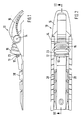
- Figures 1 to 3 is a cross-country or touring ski binding 10 shown in the assembled state. This bond is used to fix a corresponding ski boot on his front sole, especially at his front sole end complementary insertable into engagement elements of the binding 10 Engagement elements for producing a joint-like connection has, the sole-side engagement elements a crosswise to the longitudinal direction of the ski and approximately parallel to the sole tread extending joint axis include.
- the complementary Engagement elements of the bond 10 are formed by one on the top of the binding across the length of the ski and groove 12 extending parallel to the ski top surface Inclusion of the joint axis on the sole as well as an in Closed position of the binding extending over the groove holding element 13, which by means of a on the binding 10 transverse to the longitudinal direction of the ski and roughly parallel to the ski deck area extending axis 14 pivotally mounted operating lever 15 from a closed position corresponding to FIGS. 1 and 2 in a release position (right position in Figure 3) and vice versa is movable.
- a flexor 16 effective, which exerts a restoring force on the shoe, when the heel is raised from the top of the ski becomes.
- the closing and release position of the holding element 13 is by corresponding locking positions of the actuating lever 15 defined. For this purpose, in conjunction with FIG more detailed below.
- the holding element 13 is in the illustrated embodiment formed by a U-shaped wire bracket, the free ends of the two legs according to Figure 8 each are bent outwards to form fastening pins 17, which in corresponding receiving bores of the actuating lever are insertable. Via the mounting pin 17 the holding element 13 is thus coupled to the actuating lever 15.
- the two legs of the U-shaped curved Wire clips are marked with the reference number 18.
- the connecting web has the reference number 19.
- the dockside The end of the holding element 13 is used to form a pivot bearing for the shoe or sole integrated joint axis, see above as shown in Figures 1 and 3 very well.
- the Accordingly, swivel bearing is located between the web side End of the holding element 13 designed as a wire bracket on the one hand and the transverse groove 12 on the other hand limited or defined.
- the one serving as holding element 13 has Wire bracket in side view the shape of an elongated "Z", the positioning corresponding to FIG. 3 and articulation of the wire bracket on the operating lever 15 such is that the end or the joint axis of the shoe or Ridges of the wire bracket during the back and forth movement of the same extends approximately parallel to the ski deck area.
- the purpose is to bend the web end out of the base of the holding element 13 out less than the opposite Bending the free ends of the two legs 18.
- the first Angling is preferably about 18.5 degrees, while the second bend is about 45 degrees, as shown in Figure 9 is shown. 3 can be seen very well, that pivoting the operating lever 15 about the pivot axis 14 a translatory back and forth movement of the holding element 13 triggers.
- the closed position of the holding element 13 is identified in FIG. 3 by the reference number 13 ', while the open position is provided with the reference number 13 ". Accordingly, the closed position of the operating lever with the reference number 15 ', and the open position of the same with 15 ".
- the operating lever is in the open position 15 folded approximately vertically upwards according to FIG. 3.
- the holding element 13 extends through the flexor 16, the is hollow-walled, and a front binding side Stop 20 for the arranged on the front sole of the shoe Hinge axis.
- the binding has one on the ski top surface mountable base plate 21 with two laterally upwards curved cheeks 22 and a rear, when assembled, also upwardly curved edge web 23, the front Stop 20 for the arranged on the front sole of the shoe Joint axis serves.
- the described base plate is in Figures 6 and 7 shown separately, in plan view and in longitudinal section.
- the side cheeks 22 and the edge web 23 are therefore bent out of the plane of the base plate 21. Accordingly, the base plate 21 inclusive the cheeks 22 and the edge web 23 from a correspondingly cut Stainless steel sheet or the like can be produced.
- the two cheeks 22 of the base plate, which are laterally bent upward 21 each have a bore 24 for receiving serve the pivot axis 14 of the operating lever 15.
- the flexor 16 is on the base plate 21 between the two lateral cheeks 22 and the rear edge web 23 can be positioned, the pivot axis 14 of the actuating lever 15 above the flexor 16 extends across it, and within a transverse groove 25 arranged in the flexor 16, see as can be seen particularly clearly from FIGS. 10 and 11.
- the flexor is hollow in a conventional manner and consists of an elastic plastic or rubber material. Through the pivot axis 14 of the operating lever 15 the flexor 16 held on the base plate 21. additionally also serves to hold the flexor 16 on the base plate 21 Holding element 13.
- the web side extends End of the holding element 13 by a parallel to the base plate extending elongated hole in both the rear after curved top web 23 of the base plate 21 as well as in the assigned rear end wall of the flexor 16 through.
- the slot mentioned in the edge web 23 is with the reference number 26 marked.
- the corresponding slot in the back End wall of the flexor 16 has the reference number 27 on (see also Figure 7 and 11).
- the flexor has the shape in plan view of an "I", the one crosspiece being wider than the other.
- FIG. 3 show very well that the Flexor 16 exclusively through the holding element 13 and the pivot axis 14 of the actuating lever 15 is held. Accordingly, these point two aforementioned components each have a double function on.
- the one with the shoe or sole integrated joint axis too the joint axis corresponds to the shape without the risk of unintentional opening of the binding held in the transverse groove 12.
- FIG 5 are the locking positions of the holding element 13 by laterally arranged on the actuating lever 15, namely molded locking projections or locking knobs 30 and 31 on the one hand and arranged on the side cheeks 22 of the base plate 21 Notches or the front and / or rear boundary 32 and 33 of the side cheeks 22 on the other hand defined.
- the locking recess assigned to the locking knob 31 in the associated side wall 22 is in Figure 5 with the reference number 34 indicated.
- the interaction of the Latches 30 with the front and rear limit 32, 33 the lateral cheek 22 serves to fix the open position, which is shown in Figure 5.
- the operating lever 15 is preferably made of plastic, so that the molding the detent 30, 31 is not too expensive. When interacting this locking knob with the front and rear limits the side cheeks 22 can be the design effort reduce additionally.
- the operating lever 15 is in association to a modified holding element 13 both in the binding open position ( Figures 13 - 15) as well as in the ski position the binding ( Figures 16-18), the two legs 18 of the serving as holding element 13, approximately Slightly U-shaped wire bracket when unloaded Are spread apart in a V-shape, as shown in FIG 18 is shown.
- the elastic preload of the two Leg 18 is indicated in Figure 17 with the double arrow 35.
- At least one of the two legs 18, here both legs 18, have in the area near the binding web 19 between the two legs 18 each have an inwardly extending Dent in the form of a bend 34, which in the closed Condition of the binding according to Figures 16-18 with the assigned lateral limitation of the in the base plate 21st trained slot 26 through which the wire bracket 18th extends through, engages interactively. In this way is a backup, especially an additional backup of the Binding given in the closed position.
- the two legs 18 are assigned by Sloping surfaces on the inside of the operating lever 15 against the radial preload 35 according to FIG inside, d. H. moved towards each other in a position according to Figures 14 and 15. This is the snap connection between the Bends 34 and the lateral boundary of the elongated hole 26 canceled in the base plate 21, so that the as a holding element 13 serving wire brackets in the Can move shoe release position.
Landscapes
- Footwear And Its Accessory, Manufacturing Method And Apparatuses (AREA)
- Addition Polymer Or Copolymer, Post-Treatments, Or Chemical Modifications (AREA)
- Transition And Organic Metals Composition Catalysts For Addition Polymerization (AREA)
- Materials Applied To Surfaces To Minimize Adherence Of Mist Or Water (AREA)
- Acyclic And Carbocyclic Compounds In Medicinal Compositions (AREA)
Applications Claiming Priority (3)
| Application Number | Priority Date | Filing Date | Title |
|---|---|---|---|
| DE19623825A DE19623825C1 (de) | 1996-06-14 | 1996-06-14 | Langlauf- oder Tourenskibindung |
| DE19623825 | 1996-06-14 | ||
| EP97924192A EP0904139B1 (fr) | 1996-06-14 | 1997-06-13 | Fixation pour ski de fond ou ski de randonnee |
Related Parent Applications (2)
| Application Number | Title | Priority Date | Filing Date |
|---|---|---|---|
| EP97924192A Division EP0904139B1 (fr) | 1996-06-14 | 1997-06-13 | Fixation pour ski de fond ou ski de randonnee |
| EP97924192.4 Division | 1997-12-18 |
Publications (3)
| Publication Number | Publication Date |
|---|---|
| EP1226850A2 true EP1226850A2 (fr) | 2002-07-31 |
| EP1226850A3 EP1226850A3 (fr) | 2003-08-20 |
| EP1226850B1 EP1226850B1 (fr) | 2005-12-21 |
Family
ID=7796984
Family Applications (3)
| Application Number | Title | Priority Date | Filing Date |
|---|---|---|---|
| EP02007415A Expired - Lifetime EP1226850B1 (fr) | 1996-06-14 | 1997-06-13 | Fixation pour skis de fond ou skis de randonnée |
| EP97924192A Expired - Lifetime EP0904139B1 (fr) | 1996-06-14 | 1997-06-13 | Fixation pour ski de fond ou ski de randonnee |
| EP03002570A Expired - Lifetime EP1306110B1 (fr) | 1996-06-14 | 1997-06-13 | Fixation pour ski de fond ou ski de randonnée |
Family Applications After (2)
| Application Number | Title | Priority Date | Filing Date |
|---|---|---|---|
| EP97924192A Expired - Lifetime EP0904139B1 (fr) | 1996-06-14 | 1997-06-13 | Fixation pour ski de fond ou ski de randonnee |
| EP03002570A Expired - Lifetime EP1306110B1 (fr) | 1996-06-14 | 1997-06-13 | Fixation pour ski de fond ou ski de randonnée |
Country Status (6)
| Country | Link |
|---|---|
| US (1) | US6027135A (fr) |
| EP (3) | EP1226850B1 (fr) |
| AT (3) | ATE302638T1 (fr) |
| DE (4) | DE19623825C1 (fr) |
| NO (1) | NO306851B1 (fr) |
| WO (1) | WO1997047367A1 (fr) |
Cited By (4)
| Publication number | Priority date | Publication date | Assignee | Title |
|---|---|---|---|---|
| WO2008051106A1 (fr) * | 2006-10-26 | 2008-05-02 | Stanislav Viktorovich Mozgovoy | Fixations automatiques pour ski de fond |
| WO2008065499A1 (fr) * | 2006-11-28 | 2008-06-05 | Rottefella As | Fixation de ski |
| WO2008065498A3 (fr) * | 2006-11-28 | 2008-08-07 | Rottefella As | Dispositif de raccordement d'une chaussure à un engin de glisse |
| RU2362603C1 (ru) * | 2006-10-26 | 2009-07-27 | Станислав Викторович Мозговой | Автоматические крепления для беговых лыж |
Families Citing this family (21)
| Publication number | Priority date | Publication date | Assignee | Title |
|---|---|---|---|---|
| USD532475S1 (en) | 2004-12-16 | 2006-11-21 | Rottefella As | Mounting plate for a ski binding |
| FR2882658B1 (fr) | 2005-03-07 | 2007-05-04 | Salomon Sa | Dispositif de fixation a double commande |
| FR2890317B1 (fr) | 2005-09-08 | 2007-11-23 | Salomon Sa | Dispositif de fixation a ancrage perfectionne |
| FR2894836B1 (fr) | 2005-12-16 | 2008-02-22 | Salomon Sa | Ensemble ski de fond et dispositif de fixation de ski de fond |
| FR2899121B1 (fr) * | 2006-03-29 | 2008-07-04 | Salomon Sa | Ensemble ski de fond et dispositif de fixation de ski de fond |
| US9028329B2 (en) | 2006-04-13 | 2015-05-12 | Igt | Integrating remotely-hosted and locally rendered content on a gaming device |
| US8992304B2 (en) | 2006-04-13 | 2015-03-31 | Igt | Methods and systems for tracking an event of an externally controlled interface |
| US8784196B2 (en) | 2006-04-13 | 2014-07-22 | Igt | Remote content management and resource sharing on a gaming machine and method of implementing same |
| US20090156303A1 (en) | 2006-11-10 | 2009-06-18 | Igt | Bonusing Architectures in a Gaming Environment |
| US9311774B2 (en) | 2006-11-10 | 2016-04-12 | Igt | Gaming machine with externally controlled content display |
| FR2910337B1 (fr) * | 2006-12-20 | 2009-06-05 | Salomon Sa | Article comprenant un bouton mobile entre au moins deux positions |
| US8051794B2 (en) | 2008-03-31 | 2011-11-08 | Shimano Inc. | Rowing boat footrest assembly |
| FR2946545B1 (fr) * | 2009-06-16 | 2011-07-15 | Salomon Sas | Fixation pour ski et ski associe |
| WO2011006544A1 (fr) * | 2009-07-17 | 2011-01-20 | Rottefella As | Fléchisseur à pince de fixation |
| CA2767886C (fr) | 2009-08-04 | 2017-02-21 | Rottefella As | Mecanisme de verrouillage pour fixation de ski |
| NO20101289A1 (no) * | 2010-09-15 | 2012-03-16 | Rottefella As | Langrennsbinding, samt fremgangsmate for sammenstilling av nevnte langrennsbinding |
| NO336669B1 (no) * | 2012-11-19 | 2015-10-19 | Rottefella As | Skibinding |
| GB201513921D0 (en) | 2015-08-05 | 2015-09-23 | Immatics Biotechnologies Gmbh | Novel peptides and combination of peptides for use in immunotherapy against prostate cancer and other cancers |
| EA038895B1 (ru) * | 2017-12-28 | 2021-11-03 | Станислав Викторович МОЗГОВОЙ | Флексор лыжного крепления |
| RU197293U1 (ru) * | 2020-02-03 | 2020-04-20 | Роман Владимирович Шамов | Фиксирующий механизм с перекрытием паза, в котором в рабочем состоянии располагается шпилька ботинка |
| RU200307U1 (ru) * | 2020-06-15 | 2020-10-16 | Общество с ограниченной ответственностью "ТРЕК" | Крепление для лыж |
Citations (1)
| Publication number | Priority date | Publication date | Assignee | Title |
|---|---|---|---|---|
| DE3924915A1 (de) | 1988-08-16 | 1990-02-22 | Salomon Sa | Langlaufskibindung der scharnierbauart |
Family Cites Families (13)
| Publication number | Priority date | Publication date | Assignee | Title |
|---|---|---|---|---|
| DE3128009C2 (de) * | 1981-07-15 | 1986-12-04 | Trak Sportartikel GmbH, 8028 Taufkirchen | Langlaufski mit einer Bindung |
| FR2632539A1 (fr) * | 1988-06-09 | 1989-12-15 | Salomon Sa | Fixation de ski de fond |
| FR2634132B1 (fr) * | 1988-07-13 | 1992-10-23 | Salomon Sa | Dispositif de fixation notamment pour chaussure de ski de fond |
| FR2635014B1 (fr) * | 1988-08-05 | 1990-10-12 | Salomon Sa | Fixation de ski de fond a fermeture automatique |
| FR2645760B1 (fr) * | 1989-04-12 | 1991-06-14 | Salomon Sa | Dispositif de fixation d'une chaussure a un ski de fond |
| FR2645758B1 (fr) * | 1989-04-12 | 1991-06-14 | Salomon Sa | Dispositif de fixation d'une chaussure a un ski de fond |
| FR2645764B1 (fr) * | 1989-04-12 | 1991-06-14 | Salomon Sa | Fixation pour ski de fond |
| FR2650192B1 (fr) * | 1989-07-28 | 1991-10-25 | Salomon Sa | Fixation pour ski de fond et tampon elastique destine a une telle fixation |
| DE4010929A1 (de) * | 1990-04-04 | 1991-10-10 | Walter Dekanovsky | Langlaufskibindung |
| FR2660569B1 (fr) * | 1990-04-06 | 1993-07-09 | Salomon Sa | Fixation pour ski de fond. |
| FR2666020B1 (fr) * | 1990-08-21 | 1992-12-11 | Salomon Sa | Fixation pour ski de fond. |
| DE9200453U1 (de) * | 1992-01-16 | 1992-03-05 | Rottefella AS, Oslo/Osló | Langlauf- oder Tourenskibindung für Langlaufskischuhe |
| DE9320530U1 (de) * | 1993-09-16 | 1994-10-13 | Rottefella As, Klokkarstua | Langlauf- oder Tourenskibindung für Langlaufskischuhe |
-
1996
- 1996-06-14 DE DE19623825A patent/DE19623825C1/de not_active Expired - Fee Related
-
1997
- 1997-06-13 DE DE59712532T patent/DE59712532D1/de not_active Expired - Lifetime
- 1997-06-13 EP EP02007415A patent/EP1226850B1/fr not_active Expired - Lifetime
- 1997-06-13 WO PCT/IB1997/000699 patent/WO1997047367A1/fr not_active Ceased
- 1997-06-13 AT AT03002570T patent/ATE302638T1/de not_active IP Right Cessation
- 1997-06-13 DE DE59709353T patent/DE59709353D1/de not_active Expired - Lifetime
- 1997-06-13 EP EP97924192A patent/EP0904139B1/fr not_active Expired - Lifetime
- 1997-06-13 DE DE59712403T patent/DE59712403D1/de not_active Expired - Lifetime
- 1997-06-13 EP EP03002570A patent/EP1306110B1/fr not_active Expired - Lifetime
- 1997-06-13 AT AT97924192T patent/ATE232752T1/de not_active IP Right Cessation
- 1997-06-13 AT AT02007415T patent/ATE313361T1/de not_active IP Right Cessation
- 1997-06-13 US US09/202,405 patent/US6027135A/en not_active Expired - Lifetime
-
1998
- 1998-12-04 NO NO19985704A patent/NO306851B1/no not_active IP Right Cessation
Patent Citations (1)
| Publication number | Priority date | Publication date | Assignee | Title |
|---|---|---|---|---|
| DE3924915A1 (de) | 1988-08-16 | 1990-02-22 | Salomon Sa | Langlaufskibindung der scharnierbauart |
Cited By (4)
| Publication number | Priority date | Publication date | Assignee | Title |
|---|---|---|---|---|
| WO2008051106A1 (fr) * | 2006-10-26 | 2008-05-02 | Stanislav Viktorovich Mozgovoy | Fixations automatiques pour ski de fond |
| RU2362603C1 (ru) * | 2006-10-26 | 2009-07-27 | Станислав Викторович Мозговой | Автоматические крепления для беговых лыж |
| WO2008065499A1 (fr) * | 2006-11-28 | 2008-06-05 | Rottefella As | Fixation de ski |
| WO2008065498A3 (fr) * | 2006-11-28 | 2008-08-07 | Rottefella As | Dispositif de raccordement d'une chaussure à un engin de glisse |
Also Published As
| Publication number | Publication date |
|---|---|
| DE19623825C1 (de) | 1998-01-08 |
| NO985704L (no) | 1999-02-11 |
| EP1306110A2 (fr) | 2003-05-02 |
| EP1226850B1 (fr) | 2005-12-21 |
| US6027135A (en) | 2000-02-22 |
| NO985704D0 (no) | 1998-12-04 |
| DE59712403D1 (de) | 2005-09-29 |
| ATE232752T1 (de) | 2003-03-15 |
| DE59709353D1 (de) | 2003-03-27 |
| ATE313361T1 (de) | 2006-01-15 |
| WO1997047367A1 (fr) | 1997-12-18 |
| DE59712532D1 (de) | 2006-01-26 |
| NO306851B1 (no) | 2000-01-03 |
| EP1306110A3 (fr) | 2003-08-20 |
| EP1306110B1 (fr) | 2005-08-24 |
| EP0904139A1 (fr) | 1999-03-31 |
| EP1226850A3 (fr) | 2003-08-20 |
| EP0904139B1 (fr) | 2003-02-19 |
| ATE302638T1 (de) | 2005-09-15 |
Similar Documents
| Publication | Publication Date | Title |
|---|---|---|
| EP1226850B1 (fr) | Fixation pour skis de fond ou skis de randonnée | |
| EP0551899B1 (fr) | Fixation de ski de fond ou de ski de randonnée pour des chaussures de ski de fond | |
| EP1292369B1 (fr) | Ensemble constitue d'une fixation de ski et d'une chaussure de ski | |
| EP0265459B1 (fr) | Fixation de ski de fond | |
| DE69504518T2 (de) | Bindung für einen schuh auf einem snowboard | |
| DE4428154C2 (de) | Anordnung einer Langlaufskibindung und eines daran angepaßten Langlaufskischuhs | |
| EP1559455B1 (fr) | Fixation adaptée au ski de randonnée | |
| EP2097142A1 (fr) | Fixation de ski | |
| EP0830185B1 (fr) | Dispositif pour fixation de ski de fond, en particulier pour la pratique du patinage | |
| DE4424737C1 (de) | Snowboardbindung | |
| EP0951926B1 (fr) | Fixation de ski de randonnée, de ski de Telemark ou de ski de fond | |
| DE69602509T2 (de) | Schuhrückhaltevorrichtung auf einem Snowboard bzw. Ski oder ähnlichem | |
| EP1790396B1 (fr) | Fixation de ski, en particulier fixation de telemark | |
| EP1848516A1 (fr) | Fixation de ski de fond ou de ski de randonnee | |
| AT412949B (de) | Langlaufbindung | |
| EP0214201A1 (fr) | Dispositif de fixation pour ski de fond. | |
| DE19631164B4 (de) | Langlauf- oder Touren-Skibindung sowie Skischuh dafür | |
| DE69502541T2 (de) | Bindungsteil, insbesondere Skibindungsteil | |
| EP1040769B1 (fr) | Chaussure de ski, en particulier pour ski de fond ou Telemark | |
| DE102005049267A1 (de) | Langlauf- oder Telemarkbindung | |
| DE102006041840A1 (de) | Langlauf- oder Telemarkbindung | |
| DE3722594A1 (de) | Langlaufski | |
| DE10361705A1 (de) | Skibindung, insbesondere Touren-, Telemark- oder Langlauf-Skibindung | |
| DE3012850A1 (de) | Langlauf-bindung fuer langlauf-ski | |
| DE8500241U1 (de) | An einem Ski befestigbare Vorrichtung zum Verhindern des Wegrutschens beim Auf- und Abstieg |
Legal Events
| Date | Code | Title | Description |
|---|---|---|---|
| PUAI | Public reference made under article 153(3) epc to a published international application that has entered the european phase |
Free format text: ORIGINAL CODE: 0009012 |
|
| 17P | Request for examination filed |
Effective date: 20020328 |
|
| AC | Divisional application: reference to earlier application |
Ref document number: 904139 Country of ref document: EP |
|
| AK | Designated contracting states |
Kind code of ref document: A2 Designated state(s): AT DE FI FR IT SE |
|
| PUAL | Search report despatched |
Free format text: ORIGINAL CODE: 0009013 |
|
| AK | Designated contracting states |
Designated state(s): AT DE FI FR IT SE |
|
| AKX | Designation fees paid |
Designated state(s): AT DE FI FR IT SE |
|
| 17Q | First examination report despatched |
Effective date: 20041227 |
|
| GRAP | Despatch of communication of intention to grant a patent |
Free format text: ORIGINAL CODE: EPIDOSNIGR1 |
|
| GRAS | Grant fee paid |
Free format text: ORIGINAL CODE: EPIDOSNIGR3 |
|
| GRAA | (expected) grant |
Free format text: ORIGINAL CODE: 0009210 |
|
| AC | Divisional application: reference to earlier application |
Ref document number: 0904139 Country of ref document: EP Kind code of ref document: P |
|
| AK | Designated contracting states |
Kind code of ref document: B1 Designated state(s): AT DE FI FR IT SE |
|
| REF | Corresponds to: |
Ref document number: 59712532 Country of ref document: DE Date of ref document: 20060126 Kind code of ref document: P |
|
| REG | Reference to a national code |
Ref country code: SE Ref legal event code: TRGR |
|
| ET | Fr: translation filed | ||
| PLBE | No opposition filed within time limit |
Free format text: ORIGINAL CODE: 0009261 |
|
| STAA | Information on the status of an ep patent application or granted ep patent |
Free format text: STATUS: NO OPPOSITION FILED WITHIN TIME LIMIT |
|
| 26N | No opposition filed |
Effective date: 20060922 |
|
| PGFP | Annual fee paid to national office [announced via postgrant information from national office to epo] |
Ref country code: AT Payment date: 20090625 Year of fee payment: 13 |
|
| PGFP | Annual fee paid to national office [announced via postgrant information from national office to epo] |
Ref country code: IT Payment date: 20090627 Year of fee payment: 13 |
|
| PG25 | Lapsed in a contracting state [announced via postgrant information from national office to epo] |
Ref country code: IT Free format text: LAPSE BECAUSE OF NON-PAYMENT OF DUE FEES Effective date: 20100613 |
|
| PG25 | Lapsed in a contracting state [announced via postgrant information from national office to epo] |
Ref country code: AT Free format text: LAPSE BECAUSE OF NON-PAYMENT OF DUE FEES Effective date: 20100613 |
|
| REG | Reference to a national code |
Ref country code: FR Ref legal event code: PLFP Year of fee payment: 20 |
|
| PGFP | Annual fee paid to national office [announced via postgrant information from national office to epo] |
Ref country code: DE Payment date: 20160607 Year of fee payment: 20 Ref country code: FI Payment date: 20160609 Year of fee payment: 20 |
|
| PGFP | Annual fee paid to national office [announced via postgrant information from national office to epo] |
Ref country code: SE Payment date: 20160613 Year of fee payment: 20 Ref country code: FR Payment date: 20160516 Year of fee payment: 20 |
|
| REG | Reference to a national code |
Ref country code: DE Ref legal event code: R071 Ref document number: 59712532 Country of ref document: DE |
|
| REG | Reference to a national code |
Ref country code: SE Ref legal event code: EUG |