EP1226879A1 - Appareils de transfert, d'inspection, et d'alimentation aligne - Google Patents
Appareils de transfert, d'inspection, et d'alimentation aligne Download PDFInfo
- Publication number
- EP1226879A1 EP1226879A1 EP00962968A EP00962968A EP1226879A1 EP 1226879 A1 EP1226879 A1 EP 1226879A1 EP 00962968 A EP00962968 A EP 00962968A EP 00962968 A EP00962968 A EP 00962968A EP 1226879 A1 EP1226879 A1 EP 1226879A1
- Authority
- EP
- European Patent Office
- Prior art keywords
- article
- conveying
- rotary disc
- conveyed article
- inspecting
- Prior art date
- Legal status (The legal status is an assumption and is not a legal conclusion. Google has not performed a legal analysis and makes no representation as to the accuracy of the status listed.)
- Granted
Links
- 238000007689 inspection Methods 0.000 title claims abstract description 16
- 230000002093 peripheral effect Effects 0.000 claims abstract description 40
- 238000010276 construction Methods 0.000 claims description 2
- 230000000694 effects Effects 0.000 description 9
- 230000001070 adhesive effect Effects 0.000 description 4
- 230000003139 buffering effect Effects 0.000 description 3
- 210000003813 thumb Anatomy 0.000 description 3
- 238000004804 winding Methods 0.000 description 3
- 235000009508 confectionery Nutrition 0.000 description 2
- 230000002950 deficient Effects 0.000 description 2
- 239000003814 drug Substances 0.000 description 2
- 230000000087 stabilizing effect Effects 0.000 description 2
- 239000000853 adhesive Substances 0.000 description 1
- XAGFODPZIPBFFR-UHFFFAOYSA-N aluminium Chemical compound [Al] XAGFODPZIPBFFR-UHFFFAOYSA-N 0.000 description 1
- 238000007664 blowing Methods 0.000 description 1
- 239000002775 capsule Substances 0.000 description 1
- 230000007547 defect Effects 0.000 description 1
- 229940079593 drug Drugs 0.000 description 1
- 238000000034 method Methods 0.000 description 1
- 238000011179 visual inspection Methods 0.000 description 1
Images


Classifications
-
- B—PERFORMING OPERATIONS; TRANSPORTING
- B65—CONVEYING; PACKING; STORING; HANDLING THIN OR FILAMENTARY MATERIAL
- B65G—TRANSPORT OR STORAGE DEVICES, e.g. CONVEYORS FOR LOADING OR TIPPING, SHOP CONVEYOR SYSTEMS OR PNEUMATIC TUBE CONVEYORS
- B65G47/00—Article or material-handling devices associated with conveyors; Methods employing such devices
- B65G47/02—Devices for feeding articles or materials to conveyors
- B65G47/04—Devices for feeding articles or materials to conveyors for feeding articles
- B65G47/12—Devices for feeding articles or materials to conveyors for feeding articles from disorderly-arranged article piles or from loose assemblages of articles
- B65G47/14—Devices for feeding articles or materials to conveyors for feeding articles from disorderly-arranged article piles or from loose assemblages of articles arranging or orientating the articles by mechanical or pneumatic means during feeding
- B65G47/1407—Devices for feeding articles or materials to conveyors for feeding articles from disorderly-arranged article piles or from loose assemblages of articles arranging or orientating the articles by mechanical or pneumatic means during feeding the articles being fed from a container, e.g. a bowl
- B65G47/1478—Devices for feeding articles or materials to conveyors for feeding articles from disorderly-arranged article piles or from loose assemblages of articles arranging or orientating the articles by mechanical or pneumatic means during feeding the articles being fed from a container, e.g. a bowl by means of pick-up devices, the container remaining immobile
- B65G47/1485—Devices for feeding articles or materials to conveyors for feeding articles from disorderly-arranged article piles or from loose assemblages of articles arranging or orientating the articles by mechanical or pneumatic means during feeding the articles being fed from a container, e.g. a bowl by means of pick-up devices, the container remaining immobile using suction or magnetic forces
Definitions
- the present invention relates to a conveying apparatus for a conveyed article inspecting apparatus for inspecting mainly a small article such as a drug medicine (a tablet, a capsule and the like), small confectionery such as a candy and the like, a washer, a button electric cell, or the like as the conveyed article in a defect inspection step, a visual inspection step, a dimensional check step or the like of the conveyed article while conveying the conveyed article, an inspecting apparatus thereof and an aligning and supplying apparatus thereof.
- a small article such as a drug medicine (a tablet, a capsule and the like), small confectionery such as a candy and the like, a washer, a button electric cell, or the like
- the conveying apparatus for conveying the conveyed article in a linear direction is structured, for example, such that the conveyed article is mounted so as to ride over a pair of parallel belts and is conveyed while being held by suction by a suction means through a gap between the belts, so that since the belts can not be elongated and narrowed in order to resist a tensile strength, in the case that the conveyed article mounted on the belts is a small article, side surfaces thereof are supported between the belts deeply and the side surface of the conveyed article can not be sufficiently inspected.
- a conventional rotary disc is structured such that a contact portion with the conveyed article is made, for example, of an aluminum metal or the like, the contact portion is easily slipped due to a low coefficient of friction, whereby a conveying state is easily changed due to a weight of the conveyed article.
- the structure of this kind of rotary disc apparatus (for example, Japanese Patent Application Laid-Open No. 61-212374) is provided with movable opposing plates constituted by a pair of mutually opposing rotary discs and having a slit which is provided in peripheral portions of the rotary discs and continuously all around the periphery thereof and has an opposing gap smaller than the small article, and a suction means having a rotary tube shaft concentrically pierced in an inner side of the movable opposing plates, communicating with an inner portion of the rotary tube shaft and sucking an air from the slit to an inner side of the movable opposing plates.
- the rotary tube shaft is provided, the air is unnecessarily sucked from the slit corresponding to a portion requiring no suction.
- the aligning and supplying apparatus is used.
- the conventional aligning and supplying apparatus is structured such that the conveyed article supplied on a turn table is exposed to an aligning operation of an aligning guide together with a rotation of the turn table, and is gradually aligned along a peripheral wall.
- the conveyed article reaching a thickness gate from the aligning guide is sorted on the border of a predetermined thickness, and the conveyed article having a thickness equal to or less than the thickness passes through the thickness gate so as to reach a width guide.
- the conveyed article reaching the width guide is sorted on the border of a predetermined width, and the conveyed article having a width equal to or less than the width passes through the width guide so as to be fed out to the conveying apparatus.
- the article having the different width and thickness and being stable in a state of turning at 90 degrees, such as the tablet or the like is sorted at the thickness gate.
- an object of the present invention is to provide a conveying apparatus which can stably execute a side surface inspection of a small article without requiring a lot of space, stably execute an inspection in a rotary disc apparatus and shut out an air in a portion requiring no suction.
- Another object of the present invention is to provide an aligning and supplying apparatus which can improve a processing efficiency even in a small article having different width and thickness and being stable in a turned state.
- a conveying apparatus comprising:
- the apparatus since the apparatus is constituted by the rotary disc portion and the linear conveying portion, it is possible to stably convey the article without requiring a lot of space even when the linear conveying portion is arranged horizontally, and further it is possible to execute a side surface inspection of the conveyed article conveyed in the rotary disc.
- a conveying apparatus as described in the first aspect, wherein ring-shaped supporting members having a high friction coefficient are provided at the opposite sides of the slit along the outer peripheral surface of the rotary disc portion.
- the supporting members in addition to the same effect as that of the first aspect, it is possible to fix the supporting members to the peripheral edge of the rotary disc portion unlike the conveying belts of the linear conveying portion and to make a cross sectional area of the supporting members smaller.
- such supporting members enable a stable inspection of the article without hindering a side surface inspection of the article and without slipping the article.
- the supporting member is constituted by a structure having a shock-absorbing property and an adhesive propertysuch as an O-ring, the article can be stably conveyed at a high speed.
- a conveying apparatus as described in the second aspect, wherein the linear conveying portion includes a first conveying portion and a second conveying portion having an identical construction, and one end of the first conveying portion is opposed to the outer peripheral surface of the rotary disc portion so that the article is transferable, whereas one end of the second conveying portion is opposed to the other end of the first conveying portion so that the article is transferable.
- a conveying apparatus as described in the third aspect, further comprising an aligning and supplying apparatus provided at a side of the rotary disk portion opposite from the first conveying portion for aligning the article and supplying the article to the outer peripheral surface of the rotary disc portion, and an air shutting means for closing the slit in a circumferential surface portion of the rotary disk portion except a section extending from the aligning and supplying apparatus to the first conveying portion with respect to a rotational direction of the rotary disc portion.
- an inspecting apparatus using the conveying apparatus described in the first aspect, the second aspect, the third aspect or the fourth aspect comprising:
- the inspecting apparatus described in the fifth aspect in addition to the same effect as that of the first aspect, the second aspect, the third aspect or the fourth aspect, it is possible to inspect respective surfaces including the side surface and both front and rear surfaces of the article, and it is possible to sort the article according to the inspection results in the sorting portion.
- an aligning and supplying apparatus on which an article having a thickness and a width different from each other can be stably placed while a thickness or width direction thereof is aligned along a longitudinal direction, comprising:
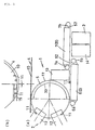
- Reference numeral 1 denotes a conveying apparatus.
- Reference numeral 2 denotes an inspecting portion.
- Reference numeral 3 denotes a sorting portion.
- Reference numeral 4 denotes an aligning and supplying apparatus.
- Reference numeral 5 denotes a rotary disc portion.
- Reference numeral 6 denotes a first conveying portion.
- Reference numeral 7 denotes a second conveying portion.
- Reference numeral 8 denotes a linear conveying portion.
- Reference numeral 10 denotes a turn table, and reference numeral 10a denotes a mounting surface.
- Reference numeral 11 denotes a conveyed article.
- Reference numeral 12 denotes a side surface inspecting portion.
- Reference numeral 13 denotes a front surface inspecting portion.
- Reference numeral 14 denotes a back surface inspecting portion.
- Reference numeral 15 denotes a width guide.
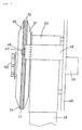
- Reference numeral 17 denotes a slit.
- Reference numeral 18 denotes a motor.
- Reference numeral 19 denotes a drive shaft.
- Reference numerals 20 and 21 denote a rotary disc.
- Reference numeral 22 denotes a suction duct.
- Reference numeral 23 denotes a supporting member.
- Reference numeral 32 denotes an air shutting means.
- Reference numeral 52 denotes a conveying belt.
- Reference numeral 55 denotes a thickness gate.
- Reference numeral 56 denotes a step portion.
- Reference numeral 57 denotes a projection portion.
- FIG. 1 shows an inspecting apparatus, which has a conveying apparatus 1, an inspecting portion 2 and a sorting portion 3.
- a conveying apparatus 1 has an aligning and supplying apparatus 4, a rotary disc portion 5, a first conveying portion 6 and a second conveying portion 7.
- the first conveying portion 6 and the second conveying portion 7 constitute a linear conveying portion 8.
- the aligning and supplying apparatus 4 is structured such that a conveyed article 11, for example, a small article, in this case, particularly a tablet is mounted on a turn table 10, and the conveyed article 11 is aligned along a peripheral edge portion in correspondence to a rotation of the turn table 10 by an aligning guide (not shown) arranged over the turn table 10 with a slight gap and is linearly fed by a width guide 15 (mentioned below) arranged near the peripheral edge portion of the turn table 10 with a slight gap so as to be supplied to the rotary disc portion 5.
- the inspecting portion 2 has two side surface inspecting portions 12 for individually inspecting both side surfaces of the conveyed article 11 on the rotary disc portion 5 one side by one side, a front surface inspecting portion 13 for inspecting a front surface of the conveyed article 11 on the first conveying portion 6, and a back surface inspecting portion 14 for inspecting a back surface of the conveyed article 11 appearing upside on the second conveying portion 7.
- a known structure provided with a light source illuminating the conveyed article 11 and a television camera picking up an image of the conveyed article 11 is applied to each of the structures in the inspecting portion 2 (for example, Japanese Patent Application Publication No. 6-088656).
- the sorting portion 3 sorts the conveyed article 11 in response to an inspected result.
- the data obtained in the inspecting portion 2 is fed to a control means, for example, an analyzer or the like so as to be compared with a reference data, an analysis for obtaining an acceptable article data or a defective article data is executed, the data is transmitted to the sorting portion 3, a timing that the sorted portion 11 comes to the sorting portion 3 is taken by counting the conveyed article 11 passing through the inspecting portion 2, and the conveyed article 11 is divided into an acceptable article collecting duct and a defective article collecting duct due to a blowing such as an air pressure in the sorting portion 3 in response to the inspected result, whereby the sorting operation is executed.
- the known structure is employed for the structure of the sorting portion 3.
- Fig. 2 shows a cross section of the rotary disc portion 5 with the suction means.
- a slit 17 is formed on an outer peripheral surface of the rotary disc portion 5, and the conveyed article 11 is conveyed in a state of being held by suction to both sides of the slit 17 by sucking through the slit 17.
- the structure has a motor 18, a pair of rotating discs 20 and 21 mounted to a drive shaft 19 of the motor 18, opposing to each other so that peripheral edges are close to each other and forming the slit 17 therebetween, for example, using platelike discs, and a fixed suction duct 22 rotatably mounting the drive shaft 19 of the motor 18.
- a pair of rotary discs 20 and 21 are mounted to a tubular connecting member 60 fitted to the drive shaft 19 so as to determine an interval of the slit 17.
- a ring-like supporting member 23 having a high friction coefficient is provided in both sides of the slit 17 along the outer peripheral surfaces of the rotary discs 20 and 21.
- a peripheral groove 24 is formed in each of the outer peripheral edges of the rotary discs 20 and 21, the supporting member 23 having a large friction coefficient, for example, an O-ring made of a article having an adhesive property and a buffering property, for example, a rubber or the like is attached thereto, and an interval of the slit 17 between the O-rings is set to be smaller than a size of the conveyed article 11, for example, about 1 mm.
- the suction duct 22 is mounted to the drive shaft 19 of the motor 18 via a bearing 25, moves the suction duct 22 close to one rotary disc 21 so as to form a gap 30 at an interval t, for example, about 0.5 mm, forms sucking holes 26 and 27 respectively communicating with opposing portions thereof, is provided with a sucking connection portion 28 on a side surface of the suction duct 22, and connects a known suction means (not shown) to the sucking connection portion 28. Accordingly, when taking out an air within the suction duct 22 by operating the suction means, a space between a pair of rotary discs 20 and 21 becomes negative pressure through the sucking holes 26 and 27, whereby the air is sucked from the slit 17 between the rotary discs 20 and 21.
- the gap 30 between the suction duct 22 and the rotary disc 21 achieves a seal effect due to a pressure loss of a fine interval.
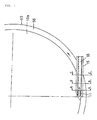
- Reference numeral 32 denotes an air shutting means.
- the air shutting means 32 closes the slit 17 of the peripheral surface portion 33 other than a peripheral surface portion reaching the first conveying portion 6 from the aligning and supplying apparatus 4 in the rotational direction of the rotary disc portion 5.
- a center portion thereof is supported to the drive shaft 19 of the motor 18 via the bearing 34 and a peripheral edge portion 35 is positioned so as to close the slit 17 of the peripheral surface portion 33.
- Fig. 3 shows an air shutting means 32.
- the air shutting means 32 is constituted by a substantially meniscus-shaped disc 36, a semicircular protruding portion 37 is provided in a center portion of a flat portion 36, the bearing 34 is provided in the protruding portion 37, and the bearing 34 is fitted to the drive shaft 19 of the motor 18, whereby the disc 36 is supported to the drive shaft 19.
- a wind guide 39 for obliquely guiding a wind at a position of the slit 17 is provided at both ends of the flat portion 36a of the disc 36.
- a fixed plate receiving groove 40 is formed in a part of a circumferential portion of the disc 36, a pair of fixed pins 41 are provided within the fixed plate receiving groove 40 in a standing manner, a front end of a fixed plate 45 having a thickness of about 0.5 mm is inserted and attached within the fixed plate receiving groove 40 between the fixed pins 41 through the slit 17, a long hole 46 longer in an inserting direction is formed at a rear end of the fixed plate 45, a fixing means inserted to the long hole 46, for example, a thumb screw 47 is fastened to one end of a fixed member 48, and the fixed plate 45 is fixed to a vertical base 49 (Fig. 5) via the fixed member 48 so as to be capable of adjusting.
- the air sucked by the suction means and moving forward from the slit 17 is limited to a portion of the rotary discs 20 and 21 where the disc 36 does not exist.
- one of the wind guide 39 faces to the aligning and supplying means 4.
- Fig. 4 shows the groove 40 and the pin 41 to which the fixed plate 45 of the disc 36 is inserted.
- Fig. 5 shows a state that another end of the fixed member 48 is mounted to the vertical base 49 to which the motor 18 is mounted, and the fixed plate 45 is fixed to one end of the fixed member 48 by the thumb screw 47.
- Reference numeral 50 denotes a fixing device for fixing the rotary disc 20 to the tubular connection member 60 (Fig. 2).
- Fig. 6 is a front elevational view of the rotary discs 20 and 21.
- the linear conveying portion 8 with the suction means sucks the conveyed article 11 riding over a pair of parallel conveying belts 52 through the gap between the conveying belts 52 as shown in Fig. 1, thereby holding the conveyed article 11 by suction to the conveying belt 52 so as to convey, in which one end opposes the outer peripheral surface of the rotary disc portion 5 so as to be capable of transferring the conveyed article 11.
- This linear conveying portion 8 is, as shown in Fig.
- first conveying portion 6 1, constituted by the first conveying portion 6 and the second conveying portion 7 having the same structure, one end of the first conveying portion 6 opposes to another of the wind guide 39 on the outer peripheral surface of the rotary disc portion 5 so as to be capable of transferring the conveyed article 11, and one end of the second conveying portion 7 opposes to another end of the first conveying portion 6 so as to be capable of transferring the conveyed article 11.
- Reference numerals 6a, 6b, 7a and 7b denote a ring body winding the conveying belt 52 therearound, for example, a pulley or the like.
- the ring bodies 6a, 6b, 7a and 7b connect one of the first conveying portion 6 and the second conveying portion 7 to a rotation driving means.
- the known structure is applied to the linear conveying portion 8 (for example, Japanese Patent Application Publication No. 5-065405).
- the aligning and supplying apparatus 4 for aligning the conveyed article 11 so as to supply to the outer peripheral surface of the rotary disc portion 5 is positioned in an opposite side of the rotary disc portion 5 to the first conveying portion 6.
- Figs. 7 and 8 are views showing details of the aligning and supplying apparatus 4 (in this case, a rotational direction of the turn table 10 is set to be opposite to Fig. 1).
- the aligning and supplying apparatus 4 is structured, for example, such as to mount the conveyed article 11 having different thickness T and width W (refer to Fig. 10) and capable of being stably mounted in a state of setting a thickness direction or a width direction to a vertical direction.
- this is a tablet in which a width is about 6 mm, a thickness is about 5 mm and a length is longer than these.
- the aligning and supplying apparatus 4 has a turn table 10, a width guide 15, a thickness gate 55, an aligning guide (not shown) and a peripheral wall (not shown).
- the turn table 10 is structured such that a sheet having a thickness of about 0.5 mm is adhered to a mounting surface 10a, and a step portion 56 having a predetermined height is provided along a peripheral edge of the mounting surface 10a.
- the step portion 56 is structured, as shown in Fig. 8, such that a sheet, for example, having a thickness of about 0.5 mm is adhered to an outer periphery.
- the aligning guide employs a known means, and is structured such as to align the conveyed article 11 mounted on the mounting surface 10a so as to be along the peripheral edge portion of the turn table 10.
- the peripheral wall (not shown) is arranged in the peripheral edge portion of the turn table 10 with a slight gap, and is structured such as to prevent the conveyed article 11 on the turn table 10 from moving out of the turn table 10 from the portion other than the width guide 15.
- the width guide 15 crosses to the step portion 56 so as to guide the conveyed article 11 mounted on the mounting surface 10a to the outer peripheral side from the center side due to the rotation of the turn table 10, for example, linearly, one end is positioned close to a center side of the turn table rather than the step portion 56, and another end protrudes outward from the outer periphery of the step portion 56 so as to be fixed (the fixing means is not shown).
- a width of the width guide 15 in accordance with the embodiment is set to a size capable of guiding the conveyed article 11 whichever of the width direction and the thickness direction is set to the vertical direction, and the conveyed article 11 aligned by the aligning guide is introduced within the width guide 15.
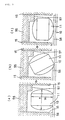
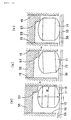
- Figs. 9 and 10 describe an operation within the width guide 15 and the thickness gate 55.
- Figs. 9A and 10A show a cross section along a line A-A in Fig. 7
- Figs. 9B and 10B show a cross section along a line B-B in Fig. 7
- Figs. 9C and 10C show a cross section along a line C-C in Fig. 7.
- the thickness gate 55 is arranged in an upper side of the conveyed article 11 passing within the width guide 15 on the turn table 10, and has a projection portion 57 protruding toward the conveyed article 11 so as to be capable of getting down the conveyed article 11 in a high attitude on a step portion 56 without getting down the conveyed article 11 in a low attitude at a time when the conveyed article 11 moving along the width guide 15 due to the rotation of the turn table 10 rides over the step portion 56.
- the thickness gate 55 is set to a height at which the conveyed article 11 can enter within the width guide 15 even in the high attitude
- the projection portion 57 is provided in one side of the width guide 15, that is, an opposite side to a side from which the step portion 56 progressively enters, so as to protrude such a degree as to contact with a side surface at an upper end of the conveyed article 11 in the high attitude, thereby getting down the conveyed article 11.
- Figs. 9A, 9B and 9C show a state in which the conveyed article 11 in the high attitude, that is, the tablet is mounted on the turn table 10 by setting the width direction to the vertical direction
- Fig. 9A shows a state in which the conveyed article 11 is introduced within the thickness gate 55 and the width guide 15.
- Fig. 9B shows a state in which the step portion 56 moves forward to about half in the width direction so as to press the side portion in the mounting side of the conveyed article 11 while the conveyed article 11 moves along one side wall of the width guide 15 due to the rotation of the turn table 10, whereby the upper end side surface of the conveyed article 11 is brought into contact with the projection portion 57 so as to be tilted in a get-down attitude.
- Fig. 9A, 9B and 9C show a state in which the conveyed article 11 in the high attitude, that is, the tablet is mounted on the turn table 10 by setting the width direction to the vertical direction
- Fig. 9A shows a state in which
- FIG. 9C shows a state in which the step portion 56 completely enters within the width guide 15.
- the conveyed article 11 rides over the step portion 56, and the conveyed article 11 simultaneously gets down on the step portion 56 so as to become in the low attitude in which the thickness direction is set to the vertical direction.
- the conveyed article 11 further moves along the width guide 15, drops down from the peripheral edge portion of the turn table 10 and drops down on the slit 17 of the rotary disc portion 5 so as to be held by suction.
- Figs. 10A, 10B and 10C show a state in which the conveyed article 11 in the low attitude, that is, the conveyed article 11 is mounted on the turn table 10 by setting the thickness direction to the vertical direction
- Fig. 10A shows a state in which the conveyed article 11 is introduced within the thickness gate 55 and the width guide 15.
- Fig. 10B shows a state in which the step portion 56 moves forward to about half in the width direction so as to press the side portion in the mounting side of the conveyed article 11 while the conveyed article 11 moves along one side wall of the width guide 15 due to the rotation of the turn table 10, whereby the conveyed article 11 is going to ride over the step portion 56.
- Fig. 10C shows a state in which the step portion 56 completely enters within the width guide 15. At this time, the conveyed article 11 rides over the step portion 56.
- the later operations are the same as those described in Fig. 9, and in any case, the conveyed article 11 drops down to the peripheral edge portion of the rotary disc portion so as to be held by suction by setting the thickness T direction to the vertical direction.
- the apparatus is constituted by the rotary disc portion 5 and the linear conveying portion 8, it is possible to stably convey with saving a space even when arranging the linear conveying portion 8 horizontally, and it is possible to execute the side surface inspection of the conveyed article 11 conveyed on the rotary disc 5.
- the supporting member 23 is constituted by a structure having a buffering property and an adhesive property, for example, an O-ring, it is possible to convey at a high speed and stably.
- the apparatus since the apparatus is constituted by the rotary disc portion and the linear conveying portion, it is possible to stably convey without requiring a lot of space even when the linear conveying portion is arranged horizontally, and further it is possible to execute a side surface inspection of the conveyed article conveyed in the rotary disc.
- the conveying apparatus described in the second aspect of the present invention in addition to the same effect as that of the first aspect, it is possible to fix the supporting member to the peripheral edge of the rotary disc portion being different from the conveying belt in the linear conveying portion and it is possible to make a cross sectional area of the supporting member small, so that it is possible to stably inspect the conveyed article without working against the side surface inspection of the conveyed article and without slipping the conveyed article.
- the supporting member is constituted by a structure having a buffering property and an adhesive property, for example, an O-ring, it is possible to convey at a high speed and stably.
- the inspecting apparatus described in the fifth aspect in addition to the same effect as that of the first aspect, the second aspect, the third aspect or the fourth aspect, it is possible to inspect respective surfaces comprising the side surface and both the surfaces of the front and back surfaces of the conveyed article, and it is possible to sort in response to an inspected result in the sorting portion.
Landscapes
- Engineering & Computer Science (AREA)
- Mechanical Engineering (AREA)
- Specific Conveyance Elements (AREA)
- Structure Of Belt Conveyors (AREA)
- Belt Conveyors (AREA)
- Diaphragms For Electromechanical Transducers (AREA)
- Chemical And Physical Treatments For Wood And The Like (AREA)
- Attitude Control For Articles On Conveyors (AREA)
- Feeding Of Articles To Conveyors (AREA)
Applications Claiming Priority (3)
| Application Number | Priority Date | Filing Date | Title |
|---|---|---|---|
| JP27859599 | 1999-09-30 | ||
| JP27859599A JP3553832B2 (ja) | 1999-09-30 | 1999-09-30 | 搬送装置、検査装置および整列供給装置 |
| PCT/JP2000/006756 WO2001023110A1 (fr) | 1999-09-30 | 2000-09-29 | Appareils de transfert, d'inspection, et d'alimentation aligne |
Publications (3)
| Publication Number | Publication Date |
|---|---|
| EP1226879A1 true EP1226879A1 (fr) | 2002-07-31 |
| EP1226879A4 EP1226879A4 (fr) | 2003-04-09 |
| EP1226879B1 EP1226879B1 (fr) | 2006-01-18 |
Family
ID=17599466
Family Applications (1)
| Application Number | Title | Priority Date | Filing Date |
|---|---|---|---|
| EP00962968A Expired - Lifetime EP1226879B1 (fr) | 1999-09-30 | 2000-09-29 | Dispositif de transport et dispositif d'inspection |
Country Status (6)
| Country | Link |
|---|---|
| US (1) | US6886683B1 (fr) |
| EP (1) | EP1226879B1 (fr) |
| JP (1) | JP3553832B2 (fr) |
| AT (1) | ATE315964T1 (fr) |
| DE (1) | DE60025633T2 (fr) |
| WO (1) | WO2001023110A1 (fr) |
Families Citing this family (8)
| Publication number | Priority date | Publication date | Assignee | Title |
|---|---|---|---|---|
| ITBO20020432A1 (it) * | 2002-07-04 | 2004-01-05 | Ima Spa | Metodo per il rilevamento ed il controllo di caratteristiche di articoli farmaceutici |
| US9511950B2 (en) * | 2011-03-14 | 2016-12-06 | The Procter & Gamble Company | Article feed system for aligning and singulating articles |
| KR101726808B1 (ko) | 2015-04-17 | 2017-04-17 | (주)엔클로니 | 정제 이송 장치 |
| CN104860035B (zh) * | 2015-04-24 | 2017-01-18 | 惠州金源精密自动化设备有限公司 | 一种电池上料设备 |
| US11006662B1 (en) * | 2015-06-19 | 2021-05-18 | Altria Client Services Llc | Bead feed unit and method |
| CN110338454B (zh) * | 2019-07-17 | 2024-02-23 | 武汉微动机器人科技有限公司 | 一种高速立式离心爆珠在线植入机构 |
| JP7279673B2 (ja) * | 2020-03-24 | 2023-05-23 | 株式会社村田製作所 | 搬送装置および搬送方法 |
| CN114789143B (zh) * | 2022-02-11 | 2022-11-15 | 中山市宏唯自动化科技有限公司 | 电池氦检测厚机及检测方法 |
Family Cites Families (18)
| Publication number | Priority date | Publication date | Assignee | Title |
|---|---|---|---|---|
| US3722658A (en) | 1971-06-23 | 1973-03-27 | Pneumatic Scale Corp | Closure handling and orienting apparatus |
| US4167226A (en) * | 1975-12-22 | 1979-09-11 | R. W. Hartnett Company, Inc. | Capsule turning apparatus (random spin printing) |
| US4393973A (en) * | 1978-09-01 | 1983-07-19 | R. W. Hartnett Company | Method and apparatus for removing non-rectified capsules from a capsule rectification and transport device |
| AU534332B2 (en) * | 1979-04-27 | 1984-01-19 | Nippon Elanco K.K. | Capsule orientation |
| FR2539057B1 (fr) | 1983-01-07 | 1985-09-13 | Applic Vibration | Appareil, a plateau rotatif, de selection d'objets |
| JPS6072418A (ja) | 1983-09-29 | 1985-04-24 | Fujitsu Ltd | 送信サンプル数処理回路 |
| JPS6072418U (ja) * | 1983-10-21 | 1985-05-22 | 村田精工株式会社 | バキユ−ム式パ−ツフイ−ダ |
| IT8415220U1 (it) | 1984-06-28 | 1985-12-28 | Carle & Montanari Spa | Dispositivo a giostra perfezionato, particolarmente adatto per l'alimentazione ordinata di prodotti in pezzi e molto delicati, ad esempio di gelatine di frutta, ad una macchina incartatrice o confezionatrice. |
| US4632028A (en) * | 1984-11-20 | 1986-12-30 | Ackley E Michael | Apparatus for orienting and printing capsules |
| DE3645233C2 (fr) | 1985-03-14 | 1993-01-28 | Kanebo, Ltd., Tokio/Tokyo, Jp | |
| JPH0688656B2 (ja) * | 1985-03-14 | 1994-11-09 | 鐘紡株式会社 | 搬送装置 |
| JPS63106225A (ja) | 1986-10-23 | 1988-05-11 | Mitsubishi Nuclear Fuel Co Ltd | 円柱体の方向転換機 |
| FR2607778B1 (fr) | 1986-12-03 | 1989-09-29 | Proto Gamma | Distributeur tangentiel de bouchons ou analogues |
| US5531312A (en) | 1994-10-24 | 1996-07-02 | Dickey; Daniel M. | Apparatus and method for singulating articles |
| JP3105752B2 (ja) | 1994-11-29 | 2000-11-06 | シオノギクオリカプス株式会社 | 偏平物品の側面検査装置、偏平物品の搬送装置及びそれらを用いた偏平物品の外観検査装置 |
| US5878868A (en) | 1996-05-06 | 1999-03-09 | Ikegami Tsushinki Co., Ltd. | Object inspection apparatus |
| JPH10170446A (ja) | 1996-12-13 | 1998-06-26 | Nippon Eranko Kk | 錠剤の姿勢変換機構及び錠剤の外観検査装置 |
| CN103716900B (zh) * | 2012-09-28 | 2017-08-25 | 中兴通讯股份有限公司 | 一种lte制式家庭基站系统中扩大网关容量的方法和装置 |
-
1999
- 1999-09-30 JP JP27859599A patent/JP3553832B2/ja not_active Expired - Lifetime
-
2000
- 2000-09-29 AT AT00962968T patent/ATE315964T1/de not_active IP Right Cessation
- 2000-09-29 EP EP00962968A patent/EP1226879B1/fr not_active Expired - Lifetime
- 2000-09-29 DE DE60025633T patent/DE60025633T2/de not_active Expired - Lifetime
- 2000-09-29 US US10/089,598 patent/US6886683B1/en not_active Expired - Lifetime
- 2000-09-29 WO PCT/JP2000/006756 patent/WO2001023110A1/fr not_active Ceased
Also Published As
| Publication number | Publication date |
|---|---|
| EP1226879A4 (fr) | 2003-04-09 |
| DE60025633T2 (de) | 2006-11-09 |
| US6886683B1 (en) | 2005-05-03 |
| DE60025633D1 (de) | 2006-04-06 |
| ATE315964T1 (de) | 2006-02-15 |
| WO2001023110A1 (fr) | 2001-04-05 |
| EP1226879B1 (fr) | 2006-01-18 |
| JP3553832B2 (ja) | 2004-08-11 |
| JP2001097550A (ja) | 2001-04-10 |
Similar Documents
| Publication | Publication Date | Title |
|---|---|---|
| JPH0565405B2 (fr) | ||
| EP1226879B1 (fr) | Dispositif de transport et dispositif d'inspection | |
| KR101533976B1 (ko) | 방향성 부품의 공급을 위한 피더 및 그의 공급 방법 | |
| CN215118859U (zh) | 晶圆取料装置 | |
| JP2004026453A (ja) | 多面体検査用フィーダー及び多面体検査装置 | |
| CN111912851A (zh) | 光学检测设备 | |
| EP1411347B1 (fr) | Dispositif pour l'inspection de comprimés plats | |
| JP4883510B2 (ja) | コンベア反転装置及びそれを用いた検査装置 | |
| JP2002068470A (ja) | 電子部品製造装置 | |
| KR100924575B1 (ko) | 전자부품 검사장치 | |
| JP4181827B2 (ja) | 直方体素子検査装置 | |
| JPH0834759B2 (ja) | 被搬送物検査方法およびその装置 | |
| JP3791698B2 (ja) | ウエハ検査装置 | |
| JP2007039142A (ja) | 搬送装置及び外観検査装置 | |
| KR20190127494A (ko) | 소형물품 외관 검사장치 | |
| JPH0432355Y2 (fr) | ||
| JP3817926B2 (ja) | チップ部品の自動分離供給装置 | |
| JP2005263467A (ja) | 検査対象物移送装置 | |
| JP3872508B1 (ja) | 小物品の外観検査方法および外観検査装置 | |
| JP2904446B2 (ja) | 円形物品の検査装置 | |
| CN222922423U (zh) | 滤清器自动排料装置 | |
| JP3490430B1 (ja) | 搬送装置 | |
| CN221551838U (zh) | 不良片剔除设备 | |
| CN117139203B (zh) | 一种基于药片翻转检测的装置及其使用方法 | |
| JP2748638B2 (ja) | 缶蓋回転装置 |
Legal Events
| Date | Code | Title | Description |
|---|---|---|---|
| PUAI | Public reference made under article 153(3) epc to a published international application that has entered the european phase |
Free format text: ORIGINAL CODE: 0009012 |
|
| 17P | Request for examination filed |
Effective date: 20020430 |
|
| AK | Designated contracting states |
Kind code of ref document: A1 Designated state(s): AT BE CH CY DE DK ES FI FR GB GR IE IT LI LU MC NL PT SE |
|
| RIN1 | Information on inventor provided before grant (corrected) |
Inventor name: TSUTSUMI, KOJI Inventor name: KAKIUCHI, SHOGO, KANEBO.LTD |
|
| RIC1 | Information provided on ipc code assigned before grant |
Free format text: 7B 07C 5/02 A, 7B 65G 47/22 B, 7B 65G 47/14 B, 7B 65G 47/84 B, 7B 65G 21/20 B, 7G 01N 21/95 B |
|
| A4 | Supplementary search report drawn up and despatched |
Effective date: 20030220 |
|
| 17Q | First examination report despatched |
Effective date: 20040303 |
|
| GRAP | Despatch of communication of intention to grant a patent |
Free format text: ORIGINAL CODE: EPIDOSNIGR1 |
|
| RTI1 | Title (correction) |
Free format text: CONVEYING APPARATUS AND INSPECTING APPARATUS |
|
| GRAS | Grant fee paid |
Free format text: ORIGINAL CODE: EPIDOSNIGR3 |
|
| GRAA | (expected) grant |
Free format text: ORIGINAL CODE: 0009210 |
|
| RAP1 | Party data changed (applicant data changed or rights of an application transferred) |
Owner name: DAIICHI JITSUGYO VISWILL CO., LTD. |
|
| AK | Designated contracting states |
Kind code of ref document: B1 Designated state(s): AT BE CH CY DE DK ES FI FR GB GR IE IT LI LU MC NL PT SE |
|
| PG25 | Lapsed in a contracting state [announced via postgrant information from national office to epo] |
Ref country code: IT Free format text: LAPSE BECAUSE OF FAILURE TO SUBMIT A TRANSLATION OF THE DESCRIPTION OR TO PAY THE FEE WITHIN THE PRESCRIBED TIME-LIMIT;WARNING: LAPSES OF ITALIAN PATENTS WITH EFFECTIVE DATE BEFORE 2007 MAY HAVE OCCURRED AT ANY TIME BEFORE 2007. THE CORRECT EFFECTIVE DATE MAY BE DIFFERENT FROM THE ONE RECORDED. Effective date: 20060118 Ref country code: LI Free format text: LAPSE BECAUSE OF FAILURE TO SUBMIT A TRANSLATION OF THE DESCRIPTION OR TO PAY THE FEE WITHIN THE PRESCRIBED TIME-LIMIT Effective date: 20060118 Ref country code: AT Free format text: LAPSE BECAUSE OF FAILURE TO SUBMIT A TRANSLATION OF THE DESCRIPTION OR TO PAY THE FEE WITHIN THE PRESCRIBED TIME-LIMIT Effective date: 20060118 Ref country code: NL Free format text: LAPSE BECAUSE OF FAILURE TO SUBMIT A TRANSLATION OF THE DESCRIPTION OR TO PAY THE FEE WITHIN THE PRESCRIBED TIME-LIMIT Effective date: 20060118 Ref country code: FI Free format text: LAPSE BECAUSE OF FAILURE TO SUBMIT A TRANSLATION OF THE DESCRIPTION OR TO PAY THE FEE WITHIN THE PRESCRIBED TIME-LIMIT Effective date: 20060118 Ref country code: CH Free format text: LAPSE BECAUSE OF FAILURE TO SUBMIT A TRANSLATION OF THE DESCRIPTION OR TO PAY THE FEE WITHIN THE PRESCRIBED TIME-LIMIT Effective date: 20060118 |
|
| REG | Reference to a national code |
Ref country code: GB Ref legal event code: FG4D |
|
| REG | Reference to a national code |
Ref country code: CH Ref legal event code: EP |
|
| REG | Reference to a national code |
Ref country code: IE Ref legal event code: FG4D |
|
| REF | Corresponds to: |
Ref document number: 60025633 Country of ref document: DE Date of ref document: 20060406 Kind code of ref document: P |
|
| PG25 | Lapsed in a contracting state [announced via postgrant information from national office to epo] |
Ref country code: SE Free format text: LAPSE BECAUSE OF FAILURE TO SUBMIT A TRANSLATION OF THE DESCRIPTION OR TO PAY THE FEE WITHIN THE PRESCRIBED TIME-LIMIT Effective date: 20060418 Ref country code: DK Free format text: LAPSE BECAUSE OF FAILURE TO SUBMIT A TRANSLATION OF THE DESCRIPTION OR TO PAY THE FEE WITHIN THE PRESCRIBED TIME-LIMIT Effective date: 20060418 |
|
| PG25 | Lapsed in a contracting state [announced via postgrant information from national office to epo] |
Ref country code: ES Free format text: LAPSE BECAUSE OF FAILURE TO SUBMIT A TRANSLATION OF THE DESCRIPTION OR TO PAY THE FEE WITHIN THE PRESCRIBED TIME-LIMIT Effective date: 20060429 |
|
| PG25 | Lapsed in a contracting state [announced via postgrant information from national office to epo] |
Ref country code: PT Free format text: LAPSE BECAUSE OF FAILURE TO SUBMIT A TRANSLATION OF THE DESCRIPTION OR TO PAY THE FEE WITHIN THE PRESCRIBED TIME-LIMIT Effective date: 20060619 |
|
| NLV1 | Nl: lapsed or annulled due to failure to fulfill the requirements of art. 29p and 29m of the patents act | ||
| REG | Reference to a national code |
Ref country code: CH Ref legal event code: PL |
|
| ET | Fr: translation filed | ||
| PG25 | Lapsed in a contracting state [announced via postgrant information from national office to epo] |
Ref country code: IE Free format text: LAPSE BECAUSE OF NON-PAYMENT OF DUE FEES Effective date: 20060929 |
|
| PG25 | Lapsed in a contracting state [announced via postgrant information from national office to epo] |
Ref country code: MC Free format text: LAPSE BECAUSE OF NON-PAYMENT OF DUE FEES Effective date: 20060930 |
|
| PLBE | No opposition filed within time limit |
Free format text: ORIGINAL CODE: 0009261 |
|
| STAA | Information on the status of an ep patent application or granted ep patent |
Free format text: STATUS: NO OPPOSITION FILED WITHIN TIME LIMIT |
|
| 26N | No opposition filed |
Effective date: 20061019 |
|
| PG25 | Lapsed in a contracting state [announced via postgrant information from national office to epo] |
Ref country code: GR Free format text: LAPSE BECAUSE OF FAILURE TO SUBMIT A TRANSLATION OF THE DESCRIPTION OR TO PAY THE FEE WITHIN THE PRESCRIBED TIME-LIMIT Effective date: 20060419 |
|
| PG25 | Lapsed in a contracting state [announced via postgrant information from national office to epo] |
Ref country code: LU Free format text: LAPSE BECAUSE OF NON-PAYMENT OF DUE FEES Effective date: 20060929 |
|
| PG25 | Lapsed in a contracting state [announced via postgrant information from national office to epo] |
Ref country code: CY Free format text: LAPSE BECAUSE OF FAILURE TO SUBMIT A TRANSLATION OF THE DESCRIPTION OR TO PAY THE FEE WITHIN THE PRESCRIBED TIME-LIMIT Effective date: 20060118 |
|
| REG | Reference to a national code |
Ref country code: FR Ref legal event code: PLFP Year of fee payment: 17 |
|
| REG | Reference to a national code |
Ref country code: FR Ref legal event code: PLFP Year of fee payment: 18 |
|
| REG | Reference to a national code |
Ref country code: FR Ref legal event code: PLFP Year of fee payment: 19 |
|
| PGFP | Annual fee paid to national office [announced via postgrant information from national office to epo] |
Ref country code: FR Payment date: 20190815 Year of fee payment: 20 Ref country code: DE Payment date: 20190917 Year of fee payment: 20 |
|
| PGFP | Annual fee paid to national office [announced via postgrant information from national office to epo] |
Ref country code: BE Payment date: 20190815 Year of fee payment: 20 |
|
| PGFP | Annual fee paid to national office [announced via postgrant information from national office to epo] |
Ref country code: GB Payment date: 20190926 Year of fee payment: 20 |
|
| REG | Reference to a national code |
Ref country code: DE Ref legal event code: R071 Ref document number: 60025633 Country of ref document: DE |
|
| REG | Reference to a national code |
Ref country code: GB Ref legal event code: PE20 Expiry date: 20200928 |
|
| REG | Reference to a national code |
Ref country code: BE Ref legal event code: MK Effective date: 20200929 |
|
| PG25 | Lapsed in a contracting state [announced via postgrant information from national office to epo] |
Ref country code: GB Free format text: LAPSE BECAUSE OF EXPIRATION OF PROTECTION Effective date: 20200928 |