EP1228930A2 - Kopfschutzairbagsystem - Google Patents
Kopfschutzairbagsystem Download PDFInfo
- Publication number
- EP1228930A2 EP1228930A2 EP02001918A EP02001918A EP1228930A2 EP 1228930 A2 EP1228930 A2 EP 1228930A2 EP 02001918 A EP02001918 A EP 02001918A EP 02001918 A EP02001918 A EP 02001918A EP 1228930 A2 EP1228930 A2 EP 1228930A2
- Authority
- EP
- European Patent Office
- Prior art keywords
- air bag
- gas
- inner tube
- main body
- bag main
- Prior art date
- Legal status (The legal status is an assumption and is not a legal conclusion. Google has not performed a legal analysis and makes no representation as to the accuracy of the status listed.)
- Granted
Links
- 238000009826 distribution Methods 0.000 claims description 67
- 238000003860 storage Methods 0.000 claims description 5
- 238000005304 joining Methods 0.000 description 32
- 238000005192 partition Methods 0.000 description 18
- 239000000463 material Substances 0.000 description 11
- 235000021189 garnishes Nutrition 0.000 description 7
- 238000010276 construction Methods 0.000 description 6
- 239000004952 Polyamide Substances 0.000 description 5
- 229920002647 polyamide Polymers 0.000 description 5
- 238000013459 approach Methods 0.000 description 3
- 239000013256 coordination polymer Substances 0.000 description 3
- 239000002184 metal Substances 0.000 description 3
- 239000006185 dispersion Substances 0.000 description 2
- 239000004744 fabric Substances 0.000 description 2
- 238000005259 measurement Methods 0.000 description 2
- 238000000034 method Methods 0.000 description 2
- 229920000728 polyester Polymers 0.000 description 2
- 238000004891 communication Methods 0.000 description 1
- 238000007599 discharging Methods 0.000 description 1
- 238000002474 experimental method Methods 0.000 description 1
- 230000009969 flowable effect Effects 0.000 description 1
- 238000003780 insertion Methods 0.000 description 1
- 230000037431 insertion Effects 0.000 description 1
- 238000009434 installation Methods 0.000 description 1
- WABPQHHGFIMREM-UHFFFAOYSA-N lead(0) Chemical compound [Pb] WABPQHHGFIMREM-UHFFFAOYSA-N 0.000 description 1
- 238000012986 modification Methods 0.000 description 1
- 230000004048 modification Effects 0.000 description 1
- 229920003002 synthetic resin Polymers 0.000 description 1
- 239000000057 synthetic resin Substances 0.000 description 1
- 238000009941 weaving Methods 0.000 description 1
- 238000003466 welding Methods 0.000 description 1
- 239000002759 woven fabric Substances 0.000 description 1
Images


Classifications
-
- B—PERFORMING OPERATIONS; TRANSPORTING
- B60—VEHICLES IN GENERAL
- B60R—VEHICLES, VEHICLE FITTINGS, OR VEHICLE PARTS, NOT OTHERWISE PROVIDED FOR
- B60R21/00—Arrangements or fittings on vehicles for protecting or preventing injuries to occupants or pedestrians in case of accidents or other traffic risks
- B60R21/02—Occupant safety arrangements or fittings, e.g. crash pads
- B60R21/16—Inflatable occupant restraints or confinements designed to inflate upon impact or impending impact, e.g. air bags
- B60R21/23—Inflatable members
- B60R21/231—Inflatable members characterised by their shape, construction or spatial configuration
- B60R21/2334—Expansion control features
- B60R21/2346—Soft diffusers
-
- B—PERFORMING OPERATIONS; TRANSPORTING
- B60—VEHICLES IN GENERAL
- B60R—VEHICLES, VEHICLE FITTINGS, OR VEHICLE PARTS, NOT OTHERWISE PROVIDED FOR
- B60R21/00—Arrangements or fittings on vehicles for protecting or preventing injuries to occupants or pedestrians in case of accidents or other traffic risks
- B60R21/02—Occupant safety arrangements or fittings, e.g. crash pads
- B60R21/16—Inflatable occupant restraints or confinements designed to inflate upon impact or impending impact, e.g. air bags
- B60R21/23—Inflatable members
- B60R21/231—Inflatable members characterised by their shape, construction or spatial configuration
- B60R21/232—Curtain-type airbags deploying mainly in a vertical direction from their top edge
-
- B—PERFORMING OPERATIONS; TRANSPORTING
- B60—VEHICLES IN GENERAL
- B60R—VEHICLES, VEHICLE FITTINGS, OR VEHICLE PARTS, NOT OTHERWISE PROVIDED FOR
- B60R21/00—Arrangements or fittings on vehicles for protecting or preventing injuries to occupants or pedestrians in case of accidents or other traffic risks
- B60R21/02—Occupant safety arrangements or fittings, e.g. crash pads
- B60R21/16—Inflatable occupant restraints or confinements designed to inflate upon impact or impending impact, e.g. air bags
- B60R21/26—Inflatable occupant restraints or confinements designed to inflate upon impact or impending impact, e.g. air bags characterised by the inflation fluid source or means to control inflation fluid flow
-
- B—PERFORMING OPERATIONS; TRANSPORTING
- B60—VEHICLES IN GENERAL
- B60R—VEHICLES, VEHICLE FITTINGS, OR VEHICLE PARTS, NOT OTHERWISE PROVIDED FOR
- B60R21/00—Arrangements or fittings on vehicles for protecting or preventing injuries to occupants or pedestrians in case of accidents or other traffic risks
- B60R21/02—Occupant safety arrangements or fittings, e.g. crash pads
- B60R21/16—Inflatable occupant restraints or confinements designed to inflate upon impact or impending impact, e.g. air bags
- B60R21/23—Inflatable members
- B60R21/231—Inflatable members characterised by their shape, construction or spatial configuration
- B60R21/233—Inflatable members characterised by their shape, construction or spatial configuration comprising a plurality of individual compartments; comprising two or more bag-like members, one within the other
- B60R2021/23316—Inner seams, e.g. creating separate compartments or used as tethering means
-
- B—PERFORMING OPERATIONS; TRANSPORTING
- B60—VEHICLES IN GENERAL
- B60R—VEHICLES, VEHICLE FITTINGS, OR VEHICLE PARTS, NOT OTHERWISE PROVIDED FOR
- B60R21/00—Arrangements or fittings on vehicles for protecting or preventing injuries to occupants or pedestrians in case of accidents or other traffic risks
- B60R21/02—Occupant safety arrangements or fittings, e.g. crash pads
- B60R21/16—Inflatable occupant restraints or confinements designed to inflate upon impact or impending impact, e.g. air bags
- B60R21/26—Inflatable occupant restraints or confinements designed to inflate upon impact or impending impact, e.g. air bags characterised by the inflation fluid source or means to control inflation fluid flow
- B60R21/261—Inflatable occupant restraints or confinements designed to inflate upon impact or impending impact, e.g. air bags characterised by the inflation fluid source or means to control inflation fluid flow with means other than bag structure to diffuse or guide inflation fluid
- B60R2021/2612—Gas guiding means, e.g. ducts
- B60R2021/2617—Curtain bag nozzles
-
- B—PERFORMING OPERATIONS; TRANSPORTING
- B60—VEHICLES IN GENERAL
- B60R—VEHICLES, VEHICLE FITTINGS, OR VEHICLE PARTS, NOT OTHERWISE PROVIDED FOR
- B60R21/00—Arrangements or fittings on vehicles for protecting or preventing injuries to occupants or pedestrians in case of accidents or other traffic risks
- B60R21/02—Occupant safety arrangements or fittings, e.g. crash pads
- B60R21/16—Inflatable occupant restraints or confinements designed to inflate upon impact or impending impact, e.g. air bags
- B60R21/23—Inflatable members
- B60R21/237—Inflatable members characterised by the way they are folded
Definitions
- the present invention relates to a head protection air bag system and more particularly to a head protection air bag system having an air bag body stored in a side portion of a passenger compartment which is adapted to inflate and deploy in longitudinal directions of a vehicle body in a curtain-like fashion. Further, the present invention relates to an air bag comprising an air bag main body having a plurality of inflating portions adapted to inflate when an inflating gas is allowed to flow thereinto and an inner tube disposed within the air bag main body for guiding the inflating gas into the respective inflating portions.
- the amount of gas released from the respective gas exit ports is preferable to make the amount of gas released from the respective gas exit ports as uniform as possible in order to ensure quick and secure inflation and deployment of the air bag bodies.
- the opening areas (the diameters) of gas exit ports which are considered to provide lower gas pressures are designed to get wider as their positions are located farther from the gas releasing port of the inflator.
- the air bag main body comprises a gas-flowable portion adapted to inflate in such a manner as to separate an inside wall portion from an outside wall portion by allowing the inflating gas to flow thereinto and a non-gas-flowable portion into which no inflating gas is allowed to flow, and the gas-flowable portion comprises a plurality of inflating portions which are partitioned by the non-gas-flowable portion in such a manner as to be arranged in parallel in the axial direction of the inner tube and are made to open on the inner tube side thereof.
- An object of the present invention is to provide a head protection air bag system and an air bag which can ensure quick and secure deployment and inflation of the air bag body and .
- the inflator activates the inflation gas from the inflator is supplied into the inflation chambers of the air bag body via the gas exit ports (supply ports) of the gas distribution means, so that the air bag body deploys in a curtain-like fashion to thereby protect the head of the driver or a front-seat passenger and/or the head of a rear-seat passenger.
- the internal pressure of the gas distribution means is increased in the vicinity of the closed distal end portion, since the opening area of the gas exist port next to the distal end portion of the gas distribution means is smaller than that of the gas exit port next thereto, the condition of gas released from the respective gas exit ports can be made substantially equal.
- by closing the distal end portion of the gas distribution means not only can the burst of the air bag body be prevented but also quick and secure deployment and inflation of the air bag body can be ensured.
- a second head protection air bag system comprising an inflator disposed at the front, rear or in a central portion of an air bag body and a gas distribution means connected to the inflator, disposed within a gas passage of the air bag body and having a distal end portion which is closed, wherein an inflation gas from the inflator is supplied into inflation chambers of the air bag body via gas exit ports (supply ports) formed longitudinally in the gas distribution means at predetermined intervals, and the opening area of at least one of the gas exit ports of the gas distribution means is wider than the opening areas of at least one of the gas exit ports which are located nearer to the gas releasing port of the inflator and at least one of the gas exit ports which are located nearer to the distal end portion of the gas distribution means.
- the inflator activates the inflation gas from the inflator is supplied into the inflation chambers of the air bag body via the gas exit ports (supply ports) of the gas distribution means, so that the air bag body deploys in a curtain-like fashion to thereby protect the head of the driver or a front-seat passenger and/or the head of a rear-seat passenger.
- a third head protection air bag system comprising an inflator disposed at the front, rear or in a central portion of an air bag body and a gas distribution means connected to the inflator, disposed within a gas passage of the air bag body and having a distal end portion which is closed, wherein an inflation gas from the inflator is supplied into inflation chambers of the air bag body via gas exit ports (supply ports) formed longitudinally in the gas distribution means at predetermined intervals, and the opening area of the gas exit port which is located farther from the gas releasing port of the inflator is made equal to or wider than the opening area of the gas exit port next thereto on the nearer side thereof to the gas releasing port of the inflator and in that the opening area of the gas exit port next to the distal end portion of the gas distribution means is made smaller than the opening area of a gas exit port next to the gas exit port.
- the configuration of the closed distal end portion of the gas distribution means may be formed into a downwardly oriented curved or tapered configuration so that the flow of gas within the gas distribution means is directed towards the gas exit port located at the distal end of the gas distribution means.
- the flow of gas within the gas distribution means is disturbed by gas rebounded from the distal end portion at the closed distal end portion of the gas distribution means, and the condition of gas released from the distal end gas exit port tends to be dispersed.
- the disturbance to the flow of gas can be suppressed by forming the closed distal end of the gas distribution means into the downwardly oriented curved or tapered configuration so that the flow of gas within the gas distribution means is directed towards the gas exit port at the distal end, whereby gas flows smoothly towards the gas exit port at the distal end of the gas distribution means.
- the dispersion in volume of gas released from the respective gas exit ports can be kept small to thereby reduce the deployment time of the air bag body.
- the inflator activates the inflation gas from the inflator is supplied into the inflation chambers of the air bag body via the gas exit ports (supply ports) of the gas distribution means, so that the air bag body deploys in a curtain-like fashion to thereby protect the head of the driver or a front-seat passenger and/or the head of a rear-seat passenger.
- the opening area of the gas exit port (supply port) formed in the closed distal end portion is made equal to those of the other gas exit ports.
- the air bag body can be deployed downwardly substantially uniformly.
- an air bag for a head protecting air bag system comprising: an air bag main body which can deploy in such a manner as to cover an opening on the inside a vehicle when an inflating gas flows into the air bag main body, and an inner tube disposed within the air bag main body for guiding an inflating gas from an inflator into the air bag main body, the air bag main body comprising a gas-flowable portion which can inflate in such a manner as to separate an inside wall portion from an outside wall portion when the inflating gas flows into the gas-flowable portion and a non-gas-flowable portion into which no inflating gas is allowed to flow, the gas-flowable portion comprising a plurality of inflating portions which are arranged in parallel with each other along an axial direction of the inner tube while being partitioned by the non-gas-flowable portion and which each have an inlet port portion made to open towards the inner tube, the inner tube being provided with supply ports which are disposed in such a manner as to confront the respective inlet port portions and are
- At least the supply port of the inner tube which is disposed in the vicinity of the inflator is disposed to be offset closer to the inflator than the widthwise center of the inlet port portion which communicates with the supply port. Namely, a distance between the supply port located in the vicinity of the inflator and the non-gas-flowable portion on a side of the perimeter of the inlet port portion of the inflating portion which communicates with the supply port which side is far away from the inflator.
- the pressure of the inflating gas exerted to the location of this non-gas-flowable portion can be suppressed to as low a pressure as possible, thereby making it possible to prevent a gas leakage from near the boundary between the non-gas-flowable portion and the inflating portion.
- the supply ports of the inner tube may be disposed in such a manner as to open downwardly without extending across folds of the air bag main body when the air bag main body has completely been folded up.
- the air bag main body may be folded up in such a manner that the supply ports of the inner tube open substantially centrally in the transverse direction of the air bag main body so folded up on a side where the folds of the air bag main body have not yet been unfolded when the inner tube has inflated substantially completely after an inflating gas has been allowed to flow into the air bag.
- the inflating gas when the inflating gas is discharged from the inflator, firstly, the inflating gas is allowed to flow into the inner tube, whereby the inflation of the inner tube is substantially completed. Thereafter, the inflating gas flows into the air bag main body from the supply ports of the inner tube. Then, when the inflation of the inner tube is substantially completed, the supply ports are disposed in such a manner as to open downwardly at the substantially central portion in the transverse direction of the air bag main body so folded up. Owing to this, the inflating gas eventually flows into the air bag main body from the supply ports while downwardly pushing the portions of the air bag main body where the folds have not yet been unfolded along the folding direction.
- the air bag main body smoothly projects downwardly along the folding direction of the air bag main body while unfolding the folds at the portions where the folds have not yet been unfolded without largely deflecting towards the inside or outside of the vehicle, whereby the deployment and inflation of the air bag main body can be completed.
- the air bag main body having the inner tube disposed therein is allowed to deploy and inflate quickly.
- the inflating gas when the inflating gas is discharged from the inflator, firstly, the inflating gas is allowed to flow into the inner tube, whereby the inflation of the inner tube is substantially completed. Thereafter, the inflating gas flows into the air bag main body from the supply ports of the inner tube. Then, when the inflation of the inner tube is substantially completed, the supply ports are disposed in such a manner as to open downwardly without striding across the folds of the air bag main body. Owing to this, the inflating gas eventually flows into the air bag main body from the supply ports while downwardly pushing the portions of the air bag main body where the folds have not yet been unfolded along the folding direction.
- the air bag main body would largely deflect towards the folds on the side where the supply ports are disposed or towards the outside or inside of the vehicle in the initial stage of deployment and inflation of the air bag main body. Owing to this, the air bag main body interferes with members existing on the perimeter thereof unnecessarily, leading to a case where the air bag main body is not allowed to deploy and inflate quickly.
- the inflating gas eventually flows into the air bag main body from the supply ports while downwardly pushing the portions of the air bag main body where the folds of the air bag main body have not yet been unfolded in the folding direction.
- the air bag main body smoothly projects downwardly along the folding direction of the air bag main body while unfolding the folds at the portions where the folds have not yet been unfolded without largely deflecting towards the inside or outside of the vehicle, whereby the deployment and inflation of the air bag main body can be completed.
- the air bag main body having the inner tube disposed therein is allowed to deploy and inflate quickly.
- the inflating gas when the inflating gas is discharged from the inflator, firstly, the inflating gas is allowed to flow into the inner tube, whereby the inflation of the inner tube is substantially completed. Thereafter, the inflating gas flows into the air bag main body from the supply ports of the inner tube. Then, since the supply ports of the inner tube are disposed on the distal end side in the folded state, when the inflation of the inner tube is substantially completed, the supply ports are disposed in such a manner as to open downwardly at the substantially central portion in the transverse direction of the air bag main body so folded up.
- the air bag main body having the inner tube disposed therein is allowed to deploy and inflate quickly.
- the air bag main body smoothly projects downwardly along the folding direction of the air bag main body while unfolding the folds at the portions where the folds have not yet been unfolded without largely deflecting towards the inside or outside of the vehicle, whereby the deployment and inflation of the air bag main body can be completed.
- the air bag main body having the inner tube disposed therein is allowed to deploy and inflate quickly.
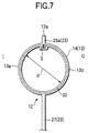
- an air bag for a head protection air bag system comprising an air bag main body adapted to deploy and inflate so as to cover an opening on the inside of a vehicle when an inflating gas is allowed to flow thereinto, and an inner tube disposed within the air bag main body for guiding an inflating gas from an inflator into the air bag main body, the air bag main body comprising a plurality of inflating portions arranged in parallel in an axial direction of the inner tube and each adapted to inflate when the inflating gas is allowed to flow thereinto in such a manner that an inside wall portion separates from an outside wall portion, the inner tube comprising a plurality of supply ports for supplying the inflating gas into the respective inflating portions, the air bag for a head protection air bag system being characterized in that assuming that the inside diametrical dimension of the inner tube is set to fall within a range of ⁇ 25 to 60, the cross-sectional area of the inner tube when it has inflated is So and the lengthwise dimension L of the inner
- the internal pressure inside the inner tube resulting when the inner tube is inflated by allowing the inflating gas to flow from the inflator into the inner tube can be made substantially uniform. Owing to this, after the inflation of the inner tube is completed, the amount of the inflating gas allowed to flow into the respective inflating portions from the supply ports can be made substantially constant, whereby the respective inflating portions are allowed to deploy and inflate in such a manner that the deployment time thereof becomes substantially uniform.
- the air bag main body having the inner tube disposed therein is allowed to deploy and inflate in such a manner that the respective inflating portions inflate uniformly.
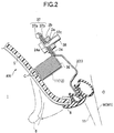
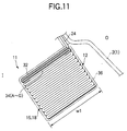
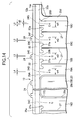
- an air bag 11 is folded up to be stored over a lower edge side of a front pillar portion FP, a lower edge side of a roof side rail portion RR and an upper side of a rear pillar portion RP of an upper edge circumferential edge of an opening W (W1, W2) in a door or window on the inside of a vehicle V.
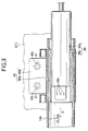
- the mounting brackets 37 are each formed of a sheet metal and are designed to hold respective mounting portions 24 on the air bag 11, which will be described later.
- the mounting brackets 37 each comprise an inner plate 37a on the inside I of the vehicle and an outer plate 37b on the outside O of the vehicle.
- Amounting hole 37c corresponding to a mounting hole 24a in the mounting portion 24 is formed in the inner and outer plates 37a, 37b in such a manner as to penetrate therethrough.
- a mounting bolt 38 is passed through the mounting holes 24a, 37c to be screwed into a nut 2b fixedly secured to the circumferential edge of the mounting hole 2a in the inner panel 2, whereby each mounting portion 24 is mounted to the inner panel 2.
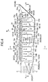
- the front-seat gas-flowable portion 15 is disposed below a front side of the tube disposing portion 14 and is disposed to be on the side of the front seat of the vehicle V when the air bag 11 deploys and inflates, whereby the front-seat gas-flowable portion 15 inflates to cover the opening W1 existing on the side of the front seat.
- the rear-seat gas-flowable portion 18 is disposed below a rear side of the tube disposing portion 14 and is disposed to be on the side of the rear seat of the vehicle V when the air bag 11 deploys and inflates, whereby the rear-seat gas-flowable portion 18 inflates to cover the opening W2 existing on the side of the rear seat.
- the tube disposing portion 14 comprises the connecting port portion 14a at a rear end thereof.
- the connecting port portion 14a is made to open at the rear end and is formed substantially into a cylindrical configuration in such a manner as to project from the air bag main body 12.
- the tube disposing portion 14 extends linearly towards the front from the connecting port portion 14a to be disposed above the front-seat gas-flowable portion 15.
- the connecting port portion 14a is, as has been described above, constructed to fit on the inflator 39 with an inner tube rear end 32a being interposed therebetween.
- the front-seat and rear-seat gas-flowable portions 15, 18 are each partitioned with partition joining portions 27, which will be described later and are constituted by a plurality of inflating portions 16, 19 disposed in the longitudinal direction of the vehicle, respectively, while the plurality of inflating portions extend vertically.
- the inflating portion 16 of the front-seat gas-flowable portion 16 is constituted by four inflating portions 16A, 16B, 16C, 16D. Then, the inflating portion 16D disposed at the rear end connects to a front edge side of the plate-like portion 28, which will be described later, whereby a lower end 16a is made to communicate with a front end of the communicating gas-flowable portion 21.
- the respective inflating portions 16A, 16B, 16C other than the inflating portion 16D are all closed at lower end sides thereof by a lower edge side portion 25b of a circumferential edge joining portion 25, which will be described later, of the non-gas-gas-flowable portion 23 whereas upper ends of all the inflating portions 16A, 16B, 16C, 16D are made to communicate with the tube disposing portion 14.
- inlet port portions 17A, 17B, 17C, 17D which are made to communicate with a tube disposing portion 14 are formed at upper ends of the four inflating portions 16A, 16B, 16c, 16D, respectively.
- the inlet port portion 17A is formed between a front edge side portion 25c of the circumferential edge joining portion 25, which will be described later, of the non-gas-flowable portion 23 and an upper end 27a of the partition joining portion 27.
- the inlet port portions 17B, 17C are formed between upper ends 27a, 27b of partition joining portions 27, 27 which are disposed longitudinally.
- the inlet port portion 17D is formed between an upper end 27a of a partition joining portion and a circumferential edge joining portion 25e of a rectangular plate-like portion 28c, which will be described later.
- the inflating portion 19 of the rear-seat gas-flowable portion 18 is constituted by four inflating portion 19A, 19B, 19C, 19D. Then, the inflating portion 19A disposed at a front end side is made to communicate with a rear end of the communicating gas-flowable portion 21 at a lower end 19a.
- the respective inflating portions 19B, 19C, 19D other than the inflating portion 19A are all closed at lower ends thereof by the lower edge side portion 25 of the circumferential edge joining portion 25.
- upper ends of all the inflating portions 19A, 19B, 19C, 19D are made to communicate with the tube disposing portion 14.
- inlet port portions 20A, 20B, 20C, 20D which are made to communicate with the tube disposing portion 14.
- the inlet port portion 20A is formed between a circumferential edge joining portion 25e disposed around the perimeter of the rectangular plate-like portion 28c.
- the inlet port portions 20B, 20C are formed, respectively, between upper ends 27a, 27a of partition joining portions 27, 27 which are disposed longitudinally.
- the inlet port portion 20D is formed between an upper end 27a of a partition joining portion 27 and a rear edge side portion 25d of the circumferential edge joining portion 25.
- the non-gas-flowable portion 23 is constructed such that the inside wall portion 13a and the outside wall portion 13b join together and is constituted by the mounting portions 24, the circumferential edge joining portion 25, partition joining portions 27 and plate-like portion 28.
- the circumferential edge joining portion 25 is disposed at locations where it contacts the gas-flowable portion 13 around the perimeter of the gas-flowable portion 13 including the perimeter of a rectangular plate-like portion 28c, which will be described later, and is woven tightly so that there is occurring no leakage of gas.
- a plurality (in this embodiment, eight) of mounting portions 24 are disposed in such a manner as to project upwardly from an upper edge side portion 25a of the circumferential edge joining portion 25 and the plate-like portion 28 (triangular plate-like portion 28a, 28b) on the upper edge 12a side of the air bag main body 12, and the mounting brackets 37 for mounting to the inner panel 2 are fixedly secured to the mounting portions 24.
- the mounting portions 24 each have a mounting hole 24a formed therein so that the mounting bolt 38 passes therethrough.
- the plate-like portion 28 is constituted by triangular plate-like portions 28a, 28b which are disposed at the front end side and rear end side of the air bag main body 12 and the rectangular plate-like portion 28c disposed between the tube disposing portion 14 and the communicating gas-flowable portion 21 which are disposed between the front-seat gas-flowable portion 15 and the rear-seat gas-flowable portion 18 which are disposed longitudinally.
- the plate-like portion 28 secures the overall configuration of the air bag main body 12 and reduces the volume of the gas-flowable portion 13 to thereby set short a time required until the inflation of the air bag main body 12 is completed.
- the front triangular plate-like portion 28a is disposed in such a manner as to project forwards from the front edge side of the circumferential edge joining portion 25, and the rear triangular plate-like portion 28b is disposed in such a manner as to project rearwards from the rear edge side of the circumferential edge joining portion 25.
- the circumferential edge joining portion 25 is disposed between the perimeter of the rectangular plate-like portion 28C and the gas-flowable portion 13 (front-seat and rear-seat gas-flowable portions 15, 18, communicating gas-flowable portion 21, tube disposing portion 14).
- Aplurality of partition joining portions 27 are provided in parallel with each other in the longitudinal direction of the vehicle V and each take the form of a substantially "T-shape" which extends upwardly from the lower edge side portion 25b of the circumferential edge joining portion 25 to the communicating gas-flowable portion 21 within the areas of the respective front-seat and rear-seat gas-flowable portions.
- the respective partition joining portions 27 partition the inside of the respective gas-flowable portions 15, 18 into a plurality of inflating portions 16A, 16B 16C, 16D, 19A, 19B, 19C, 19D, and the partition joining portions 27 are disposed to make the thickness of the respective gas-flowable portions 15, 18 substantially equal when the respective gas-flowable portions 15, 18 inflate by allowing the inflating gas G to flow thereinto.
- the respective partition joining portions 27 exert tensions in the longitudinal direction from a position in the vicinity of the connecting port portion 14a to the front portion of the air bag main body 12, or a mounting portion 24B at the rear end of the triangular portion 32b to a mounting portion 24F at the front end of the triangular plate-like portion 32a, so that the air bag main body 12 do not swing largely towards the inside I or outside O of the vehicle even if the air bag main body is subjected to a pushing force towards the inside I or outside O of the vehicle.
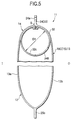
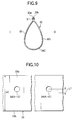
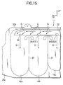
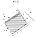
- a front end 32b of the inner tube 32 which is located far away from the connecting port portion 14a is formed into a downwardly oriented curbed configuration or an arc-like configuration as viewed from the side so that the flow of gas within the inner tube 32 (as indicated by arrows G) is directed towards a gas exit port (supply port) 34 formed at the distal end thereof as shown in Fig. 15.
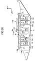
- a plurality of supply ports (gas exit ports) 34, 34A-34G are formed in the circumferential wall 32C of the inner tube 32 on a lower portion side for supplying a inflating gas G into the respective gas-flowable portions 15, 18 of the air bag main body 12.
- the respective supply ports are formed in the inner tube 32 to be made to open at positions located above the respective inflating portions 16A, 16B, 16C, 16D, 19A, 19B, 19C, 19D so that the inflating gas G can be supplied from the inner tube 32 into the respective inflating portions 16A, 16B, 16C, 16D, 19A, 19B, 19C, 19D.
- the respective supply ports 34, 34A-34G are formed such that centers thereof are positioned offset towards the edge portion 33a from the transverse center of the sheet material 33 so that the supply ports are disposed on the outside O of the vehicle body in the vicinity of the lower end of the inner tube (refer to Fig. 10).
- the supply ports are disposed in such a manner as to open downwardly at a substantially transversely central position in the folding direction of the air bag main body 12 when the air bag main body 12 has completely been folded up.
- the supply ports 34D, 34E, 34F, 34G which are disposed above the rear-seat gas-flowable portion 18 are disposed in such a manner as to be offset closer to the inflator 39 side than the transverse centers of the respective inlet port portions 20A, 20B, 20C, 20D which communicate with the respective supply ports 34D, 34E, 34F, 34G.
- This offset amount is set largest for the supply port 34G which communicates with the inflating portion 19D which is located nearest to the inflator 39, and the offset amounts of the supply ports are set such that the offset amounts become smaller sequentially as the supply ports are located farther away from the inflator 39.
- the supply ports 34, 34A-34C on the front-seat gas-flowable portion 15 are disposed at the transverse centers of the respective inlet port portions 17.
- the supply ports are set such that assuming that the cross-sectional area of the inner tube 32 resulting when it has inflated is So and the lengthwise dimension of the inner tube is L, the total opening area s of the supply ports 34, 34A, 34B, 34C, 34D, 34E, 34F, 34G is set to fall within a range expressed by the following expression; 0. 25 ⁇ 10 -3 ⁇ So/L ⁇ s ⁇ 0.55 ⁇ 10 -3 .
- the lengthwise dimension L of the inner tube 32 is set to be 1865mm
- the inside diametrical dimension d resulting when the inner tube 32 is inflated into a cylindrical shape is ⁇ 40
- the inside diametrical dimension of the supply port 34 which is disposed at a front end side of the front-seat gas-flowable portion 15 and the supply port 34G which is disposed at a rear end side (a side in the vicinity of the inflator 39) of the rear-seat gas-flowable portion 18 are set to be ⁇ 11
- the inside diametrical dimension of the remaining supply ports 34A, 34B, 34C, 34D, 34E, 34F are set to be ⁇ 16.
- So 400 ⁇
- s 444.5 ⁇
- the respective mounting brackets 37, 40 are disposed at predetermined positions on the inner panel 2 and are passed through the respective mounting holes 24a, 37c, 40c to be bolted down with the bolts 38, 41, whereby the respective mounting brackets 37, 40 are fixed to the inner panel 2, the air bag assembly being thereby mounted to the body 1.
- a lead wire, not shown, which extends from a predetermined control device for the operation of the inflator is connected to the inflator 39, and the front pillar garnish 3 and the roof head lining 5 are mounted on the body 1.
- the rear pillar garnish 6 and the center pillar garnish 7 are then mounted on the body 1, whereby the air bag system M is eventually installed on the vehicle V.
- the air bag main body 12 projects smoothly downwardly along the folding direction of the air bag main body 12 while unfolding the folds of the portions 43 where the folds have not yet been unfolded (the portions of the gas-flowable portions 15, 18) without largely deflecting to the inside I or the outside O of the vehicle, whereby the deployment and inflation of the air bag is completed.
- the supply ports 34 are disposed in such a manner as to open downwardly without striding across the folds C of the air bag main body 12. Owing to this, the inflating gas G eventually flows into the air bag main body 12 from the supply ports 34 while downwardly pushing the portions 43 of the air bag main body 12 where the folds have not yet been unfolded along the folding direction.
- the air bag main body 12 would largely deflect towards the folds C on the side where the supply ports 34 are disposed or towards the outside O or inside I of the vehicle in the initial stage of deployment and inflation of the air bag main body 12. Owing to this, the air bag main body 12 interferes with members existing on the perimeter thereof unnecessarily, leading to a case where the air bag main body 12 is not allowed to deploy and inflate quickly.
- the inflating gas G eventually flows into the air bag main body 12 from the supply ports 34 while downwardly pushing the portions 43 of the air bag main body 12 where the folds of the air bag main body 12 have not yet been unfolded in the folding direction.
- the inside diameter dimension of the supply ports 34 is larger than the widthwise dimension w1 of the air bag main body 12 which is in the folded-up state, even if the center of the supply ports 34 is disposed at substantially transverse center of the folded air bag main body 12, portions of the supply ports 34 which are in the vicinity of the end portions thereof are disposed in such a manner as to stride across the folds C of the air bag main body 12.
- the inflating gas G supplied from the supply ports 34 flows into the air bag main body 12 while downwardly pushing the portions 43 of the air bag main body 12 where the folds have not yet been unfolded in the folding direction.
- the portions of the supply ports 34 in the vicinity of the end portions thereof may stride across the folds 12 of the air bag main body 12.
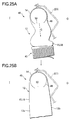
- the flow of gas (arrows G) is disturbed by gas (arrows G1) rebounded from the front end 32b at the closed front end 32b of the inner tube 32, whereby the condition of gas released from the distal end gas exit port 34 tends to be dispersed.
- the distal end configuration of the closed front end 32b of the inner tube 32 is formed into a downwardly facing curved configuration so that the flow of gas within the inner tube 32 is directed towards the gas exit port 34 at the distal end, whereby the disturbance to the flow of gas can be suppressed, thereby allowing gas to flow smoothly towards the distal end gas exit port 34.
- the dispersion in volume of gas released from the respective gas exit ports 34, 34A, 34B, 34C, 34D, 34E, 34F, 34G can be suppressed, thereby making it possible to reduce the deployment time of the air bag 11.
- the distal end configuration of the closed front distal end portion 32B of the inner tube 32 is formed into the downwardly facing curved configuration
- the distal end configuration of the closed front end 32b of the inner tube 32 may be formed into a downwardly facing tapered configuration so that the flow of gas within the inner tube 32 is directed towards the gas exit port 34 at the distal end.
- the inflator 39 when the inflator 39 is actuated, since the flowing inflating gas G becomes highest in the inflating portion 19D which is disposed in the vicinity of the inflator 39, the pressure exerted on the upper end 27a of the partition joining portion 27 which is the gas-non-flowable portion 23 located on the side which is farthest from the inflator 39 becomes highest.
- the pressure of the inflating gas G acting on the upper end 27a of the partition joining portion 27 can be suppressed to as low a pressure as possible, whereby a gas leakage from the boundary between the upper end 27a of the partition joining portion 27 and the inflating portion 19 can be prevented.
- the supply ports 34D, 34E, 34F which communicate with the inflating portions 19A, 19B, 19C in the rear-seat gas-flowable portion 18 are also disposed to be offset towards the inflator side so that the offset amounts thereof become smaller sequentially as the supply ports are located farther away from the inflator 39, there is no risk of a gas leakage from the vicinity of the boundary between the upper end 27a of the partition joining portion 27 or the circumferential edge joining portion 25e and the inflating portions 19A, 19B, 19C even in the vicinity of the inflator 39 where the pressure of inflating gas G which flows in becomes high.
- the supply ports 34D, 34E, 34F, 34G which communicate with the respective inflating portions 19A, 19B, 19C, 19D of the rear-seat gas-flowable portion 18 are offset towards the inflator side
- the supply ports 34D, 34E, 34F, 34G whose centers are offset are not limited to those supply ports, but only the supply port 34G which communicates with the inflating portion 19D positioned nearest to the inflator 39 may be offset.
- the offset amounts of the respective supply ports 34D, 34E, 34F, 34G are set such that the offset amount of the supply port 34G disposed on the inflator 39 side is set largest and that the offset amounts become smaller sequentially as they are located farther away from the inflator 39
- the offset amounts of the respective supply ports 34D, 34E, 34F, 34G may be set substantially equal to each other.
- the respective supply ports 34, 34A-34C on the front-seat gas-flowable portion 15 may be disposed so as to be offset from the transverse center of the inlet port portions 17 towards the inflator 39 side.
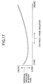
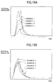
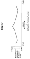
- Experimental Example 1 shows the results of measurement of internal pressures in the inner tube 32 when , the inside diametrical dimension of the supply ports 34, 34G is set to be ⁇ 9 and the inside diametrical dimension of the remaining supply ports 34A, 34B, 34C, 34D, 34E, 34F is set to be ⁇ 14.
- Experimental Example 2 shows similar results when the inside diametrical dimension of the supply ports 34, 34G is set to be ⁇ 11 and the inside diametrical dimension of the remaining supply ports 34A, 34B, 34C, 34D, 34E, 34F is set to be ⁇ 16.
- the internal pressure in the inside diameter 32 can be made substantially uniform when the inner tube 32 has inflated by allowing the inflating gas G to flow from the inflator 39.
- inflating portions 16, 19 are provided for the front-seat and rear-seat gas-flowable portions 15, 18, respectively, and eight supply ports are provided in the inner tube 32
- the numbers of inflating portions 16, 19 and supply ports are not limited to those, but the number of supply ports to be provided may optionally be set to any number selected from a range of 5 to 20.
- a plurality of supply ports may be provided at substantially uniform intervals for a single inflating portion.
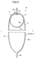
- an air bag shown in Figs. 20, 21 may be used as an air bag 46 for use in the aforesaid air bag system M.
- the airbag 46 comprises an air bag main body 12 and an inner tube 48 disposed along an upper edge side of the air bag main body 12.
- the construction of the air bag 46 is identical to that of the air bag 11 which has been described above except for the inner tube 48.
- the inflating gas G eventually flows from the supply ports into the gas-flowable portions 15, 18 while downwardly pushing the portions 43 of the air bag main body 12 where the folds have not yet been unfolded along the folding direction.
- the air bag main body 12 projects smoothly downwardly in the folding direction of the air bag main body 12 while unfolding the folds in the portions 43 where the folds have not yet been unfolded without deflecting largely to the inside I or the outside O of the vehicle, whereby the deployment and inflation of the bag main body 12 can be completed.
- the air bag comprises the inner tube having the supply ports which are disposed to be made to open at the substantially transverse center of the folded air bag main body on the side of the air bag main body where the portions exist in which the folds have not yet been unfolded when the inflation of the inner tubes is substantially completed, for example, an air bag may be used in which the inner tube is disposed in which the supply ports are formed at the position which is offset from the vicinity of the lower end of the inner tube towards the inside of the vehicle.
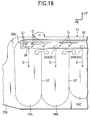
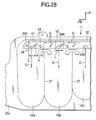
- a connecting port 129 is formed at a longitudinally central portion of an upper edge portion of an air bag 11, and a gas releasing port 114A of an inflator 114 disposed at a middle portion of a roof side rail RR is connected to a longitudinally central portion 32c of an inner tube 32. Owing to this, the inner tube 32 is closed at both a rear end 32a and a front end 32b.
- Gas exit ports (supply ports) 140, 142A, 142B, 142C are formed in the inner tube 32 along a longitudinal direction or a back-and-forth direction of a vehicle body from the rear end 32a towards the gas releasing port 114A of the inflator 114, whereas gas exit ports (supply ports) 144, 146A, 146B, 146C are formed in the inner tube 32 along the longitudinal direction or the back-and-forth direction of the vehicle body from the front end 32b to the gas releasing port 114A of the inflator 114.
- the gas pressure (the internal pressure) in the inner tube 32 becomes lower as the inner tube 32 extends farther away from the inflator 114 but the gas pressure is increased in the vicinity of the rear end 32a and the front end 32b of the closed inner tube 32.
- the condition of gas released from the respective gas exit ports 34, 34A, 34B, 34C, 34D, 34E, 34F, 34G can be made substantially equal. Owing to this, not only can the burst of the air bag 11 be prevented but also quick and secure deployment and inflation of the air bag 11 can be ensured.
- the opening area of the gas exit port 34 which eventually exists below the closed distal end 32b may be made equal to the opening areas of the other gas exit ports 34A, 34B, 34C, 34D, 34E, 34F, 34G.
- the construction of this embodiment may be applied to the rear end 32a of the inner tube 32 described in the above embodiment.
- the gas distribution means is not limited to the inner tube 32, but may be constructed differently and may be constituted by a metallic pipe.
- the invention is applied to the head protection air bag system in which the inflator is disposed at the rear pillar RP and the intermediate portion of the roof side rail RR, the invention may be applied to a head protection air bag system in which the inflator 39 is disposed at a different location such as the front pillar FR.
- the head protection air bag system according to the invention may be applied to a vehicle having three or more rows of seats.
Landscapes
- Engineering & Computer Science (AREA)
- Mechanical Engineering (AREA)
- Physics & Mathematics (AREA)
- Fluid Mechanics (AREA)
- Air Bags (AREA)
Applications Claiming Priority (10)
| Application Number | Priority Date | Filing Date | Title |
|---|---|---|---|
| JP2001023235 | 2001-01-31 | ||
| JP2001023235 | 2001-01-31 | ||
| JP2001125946A JP2002316609A (ja) | 2001-04-24 | 2001-04-24 | 頭部保護エアバッグ装置 |
| JP2001125946 | 2001-04-24 | ||
| JP2001132049 | 2001-04-27 | ||
| JP2001132049A JP3653235B2 (ja) | 2001-01-31 | 2001-04-27 | 頭部保護エアバッグ装置 |
| JP2001140323 | 2001-05-10 | ||
| JP2001140323A JP3689845B2 (ja) | 2001-05-10 | 2001-05-10 | 頭部保護エアバッグ装置のエアバッグ |
| JP2001146242A JP3711489B2 (ja) | 2001-05-16 | 2001-05-16 | 頭部保護エアバッグ装置のエアバッグ |
| JP2001146242 | 2001-05-16 |
Publications (3)
| Publication Number | Publication Date |
|---|---|
| EP1228930A2 true EP1228930A2 (de) | 2002-08-07 |
| EP1228930A3 EP1228930A3 (de) | 2003-11-12 |
| EP1228930B1 EP1228930B1 (de) | 2005-12-07 |
Family
ID=27531796
Family Applications (1)
| Application Number | Title | Priority Date | Filing Date |
|---|---|---|---|
| EP02001918A Expired - Lifetime EP1228930B1 (de) | 2001-01-31 | 2002-01-31 | Kopfschutzairbagsystem |
Country Status (3)
| Country | Link |
|---|---|
| US (1) | US20020101066A1 (de) |
| EP (1) | EP1228930B1 (de) |
| DE (1) | DE60207762T2 (de) |
Cited By (9)
| Publication number | Priority date | Publication date | Assignee | Title |
|---|---|---|---|---|
| WO2004041598A1 (en) * | 2002-11-07 | 2004-05-21 | Autoliv Development Ab | An air-bag arrangement and a method of preparing and mounting an air-bag |
| GB2397806A (en) * | 2003-01-31 | 2004-08-04 | Autoliv Dev | Air bag gas generator mounting arrangement |
| FR2855124A1 (fr) * | 2003-05-22 | 2004-11-26 | Aerazur | Sac de securite gonflable, a dispositif de maintien du generateur de gaz |
| US7380819B2 (en) | 2002-07-12 | 2008-06-03 | Autoliv Development Ab | Air-bag |
| US7422233B2 (en) | 2002-10-01 | 2008-09-09 | Autoliv Development Ab | Air-bag |
| US7425019B2 (en) | 2005-01-12 | 2008-09-16 | Autoliv Development Ab | Airbag and process for manufacture of an airbag |
| EP1462321B1 (de) * | 2003-03-24 | 2009-01-07 | Key Safety Systems, Inc. | Seitenairbag |
| US7597348B2 (en) | 2003-12-08 | 2009-10-06 | Autoliv Development Ab | Automotive airbag device |
| US7712768B2 (en) | 2003-10-27 | 2010-05-11 | Autoliv Development Ab | Side curtain air bag |
Families Citing this family (21)
| Publication number | Priority date | Publication date | Assignee | Title |
|---|---|---|---|---|
| EP1364839A3 (de) * | 2002-05-24 | 2004-02-25 | Breed Automotive Technology, Inc. | Verbesserte Seitenluftsackeinrichtung |
| US6945556B2 (en) * | 2002-11-29 | 2005-09-20 | Takata Restraint Systems, Inc. | Airbag fabric diffuser |
| JP2007511419A (ja) * | 2003-11-18 | 2007-05-10 | ティーケー ホールディングス,インコーポレーテッド | エアバッグ |
| JP4419696B2 (ja) * | 2004-06-14 | 2010-02-24 | タカタ株式会社 | カーテンエアバッグ装置 |
| US7784822B2 (en) * | 2004-07-26 | 2010-08-31 | Nxgen Technologies, Inc. | Inflatable airbag |
| US20060138760A1 (en) * | 2004-12-28 | 2006-06-29 | Takata Corporation | Airbag with gas distribution pipe |
| DE102005021371A1 (de) * | 2005-05-04 | 2006-11-23 | Autoliv Development Ab | Gassack |
| US7971899B2 (en) * | 2005-07-26 | 2011-07-05 | Nxgen Technologies, Inc. | Side curtain airbag |
| US20110057425A1 (en) * | 2005-07-26 | 2011-03-10 | Fink Michael F | Side curtain airbag |
| US8240708B2 (en) * | 2005-07-26 | 2012-08-14 | Nxgen Technologies, Llc | Side curtain airbag with fabric diffuser |
| US8366144B2 (en) * | 2005-07-26 | 2013-02-05 | Nxgen Technologies, Llc | Side curtain airbag with fabric diffuser |
| US20070228709A1 (en) * | 2006-03-30 | 2007-10-04 | Tk Holdings, Inc. | Airbag with gas diffuser |
| JP5201089B2 (ja) * | 2009-06-22 | 2013-06-05 | 豊田合成株式会社 | 頭部保護エアバッグ装置 |
| DE102011005549A1 (de) * | 2011-03-15 | 2011-07-21 | Takata-Petri Ag, 63743 | Seitengassack für ein Fahrzeuginsassen-Rückhaltesystem eines Kraftfahrzeuges |
| CN103842215B (zh) | 2011-05-02 | 2017-05-17 | NxGen技术有限责任公司 | 侧帘式安全气囊以及用于制造侧帘式安全气囊的方法和设备 |
| WO2013161626A1 (ja) * | 2012-04-23 | 2013-10-31 | 本田技研工業株式会社 | カーテンエアバッグ装置 |
| DE202013004273U1 (de) | 2013-05-07 | 2013-05-27 | Key Safety Systems, Inc. | Airbag für ein Kraftfahrzeug |
| JP6060913B2 (ja) * | 2014-01-28 | 2017-01-18 | 豊田合成株式会社 | 頭部保護エアバッグ装置 |
| CN105564359B (zh) * | 2015-12-11 | 2018-01-26 | 李金秀 | 及时充气的安全气囊 |
| US10442392B2 (en) | 2017-12-07 | 2019-10-15 | Ford Global Technologies, Llc | Vehicle seat belt system having air distribution manifold |
| US10569735B2 (en) * | 2017-12-07 | 2020-02-25 | Ford Global Technologies, Llc | Vehicle seat belt system having uniform air delivery |
Citations (4)
| Publication number | Priority date | Publication date | Assignee | Title |
|---|---|---|---|---|
| JPH10100840A (ja) | 1996-09-30 | 1998-04-21 | Toyo Tire & Rubber Co Ltd | 側部用エアバッグ装置 |
| JPH11235965A (ja) | 1998-02-20 | 1999-08-31 | Toyota Motor Corp | 頭部保護エアバッグ装置 |
| JPH11301394A (ja) | 1998-03-06 | 1999-11-02 | Trw Occupant Restraint Syst Gmbh | ガスバッグタイプ搭乗者保護システム用の連結ライン |
| JP2000127886A (ja) | 1998-08-20 | 2000-05-09 | Takata Corp | 自動車乗員頭部の保護バッグ |
Family Cites Families (6)
| Publication number | Priority date | Publication date | Assignee | Title |
|---|---|---|---|---|
| US6073961A (en) * | 1998-02-20 | 2000-06-13 | Breed Automotive Technology, Inc. | Inflatable side airbag curtain module |
| DE19812915A1 (de) * | 1998-03-24 | 1999-09-30 | Takata Europ Gmbh | Airbagvorrichtung für Kraftfahrzeuge |
| US6270113B1 (en) * | 1998-10-06 | 2001-08-07 | Breed Automotive Technology, Inc. | Side air bag system |
| US6554314B1 (en) * | 1999-02-03 | 2003-04-29 | Takata Corporation | Protective cushion for vehicle occupant's head |
| US6106006A (en) * | 1999-04-06 | 2000-08-22 | Trw Vehicle Safety Systems Inc. | Vehicle occupant protection apparatus including an inflatable curtain and a housing containing the curtain |
| US6450529B1 (en) * | 2000-06-23 | 2002-09-17 | Breed Automotive Technologies, Inc. | Inflatable side air bag curtain module with chamber separators |
-
2002
- 2002-01-28 US US10/055,889 patent/US20020101066A1/en not_active Abandoned
- 2002-01-31 EP EP02001918A patent/EP1228930B1/de not_active Expired - Lifetime
- 2002-01-31 DE DE60207762T patent/DE60207762T2/de not_active Expired - Lifetime
Patent Citations (4)
| Publication number | Priority date | Publication date | Assignee | Title |
|---|---|---|---|---|
| JPH10100840A (ja) | 1996-09-30 | 1998-04-21 | Toyo Tire & Rubber Co Ltd | 側部用エアバッグ装置 |
| JPH11235965A (ja) | 1998-02-20 | 1999-08-31 | Toyota Motor Corp | 頭部保護エアバッグ装置 |
| JPH11301394A (ja) | 1998-03-06 | 1999-11-02 | Trw Occupant Restraint Syst Gmbh | ガスバッグタイプ搭乗者保護システム用の連結ライン |
| JP2000127886A (ja) | 1998-08-20 | 2000-05-09 | Takata Corp | 自動車乗員頭部の保護バッグ |
Cited By (13)
| Publication number | Priority date | Publication date | Assignee | Title |
|---|---|---|---|---|
| US7380819B2 (en) | 2002-07-12 | 2008-06-03 | Autoliv Development Ab | Air-bag |
| US7422233B2 (en) | 2002-10-01 | 2008-09-09 | Autoliv Development Ab | Air-bag |
| WO2004041598A1 (en) * | 2002-11-07 | 2004-05-21 | Autoliv Development Ab | An air-bag arrangement and a method of preparing and mounting an air-bag |
| US7845674B2 (en) | 2002-11-07 | 2010-12-07 | Autoliv Development Ab | Air-bag arrangement and a method of preparing and mounting an air-bag |
| GB2397806A (en) * | 2003-01-31 | 2004-08-04 | Autoliv Dev | Air bag gas generator mounting arrangement |
| GB2397806B (en) * | 2003-01-31 | 2006-01-04 | Autoliv Dev | Improvements in or relating to an air-bag |
| EP1462321B1 (de) * | 2003-03-24 | 2009-01-07 | Key Safety Systems, Inc. | Seitenairbag |
| FR2855124A1 (fr) * | 2003-05-22 | 2004-11-26 | Aerazur | Sac de securite gonflable, a dispositif de maintien du generateur de gaz |
| US7712768B2 (en) | 2003-10-27 | 2010-05-11 | Autoliv Development Ab | Side curtain air bag |
| US7922192B2 (en) | 2003-10-27 | 2011-04-12 | Autoliv Development Ab | Side curtain air bag |
| EP1679235B1 (de) * | 2003-10-27 | 2015-08-26 | Autoliv Development AB | Seitenairbag |
| US7597348B2 (en) | 2003-12-08 | 2009-10-06 | Autoliv Development Ab | Automotive airbag device |
| US7425019B2 (en) | 2005-01-12 | 2008-09-16 | Autoliv Development Ab | Airbag and process for manufacture of an airbag |
Also Published As
| Publication number | Publication date |
|---|---|
| EP1228930B1 (de) | 2005-12-07 |
| EP1228930A3 (de) | 2003-11-12 |
| DE60207762D1 (de) | 2006-01-12 |
| US20020101066A1 (en) | 2002-08-01 |
| DE60207762T2 (de) | 2006-08-17 |
Similar Documents
| Publication | Publication Date | Title |
|---|---|---|
| EP1228930B1 (de) | Kopfschutzairbagsystem | |
| JP3782793B2 (ja) | 改良型のカーテンエアバッグ組立体 | |
| US7077425B2 (en) | Head protecting airbag device | |
| US6860506B2 (en) | Head protecting airbag device | |
| JP4005321B2 (ja) | 頭部保護エアバッグ装置 | |
| US8006999B2 (en) | Head protection airbag | |
| US7712768B2 (en) | Side curtain air bag | |
| EP1879773B1 (de) | Vorhangairbaganordnung | |
| JP3956863B2 (ja) | 頭部保護エアバッグ | |
| US7370882B2 (en) | Air bag system having diffuser structure | |
| US8448984B2 (en) | Airbag device | |
| US20020027338A1 (en) | Airbag apparatus | |
| US7080853B2 (en) | Airbag for head-protecting airbag device | |
| US7469922B2 (en) | Head-protecting airbag apparatus | |
| JP3607967B2 (ja) | 頭部保護エアバッグ装置 | |
| US7168735B2 (en) | Airbag apparatus | |
| JP3656156B2 (ja) | 頭部保護エアバッグ装置のエアバッグ | |
| JP2002321587A (ja) | 頭部保護エアバッグ装置 | |
| JP3858675B2 (ja) | 頭部保護エアバッグ装置 | |
| JP3689845B2 (ja) | 頭部保護エアバッグ装置のエアバッグ | |
| JP2002316609A (ja) | 頭部保護エアバッグ装置 | |
| JP2007045173A (ja) | 頭部保護エアバッグ | |
| JP3711489B2 (ja) | 頭部保護エアバッグ装置のエアバッグ | |
| JP3951664B2 (ja) | エアバッグ装置 | |
| JP2003160017A (ja) | エアバッグ装置 |
Legal Events
| Date | Code | Title | Description |
|---|---|---|---|
| PUAI | Public reference made under article 153(3) epc to a published international application that has entered the european phase |
Free format text: ORIGINAL CODE: 0009012 |
|
| 17P | Request for examination filed |
Effective date: 20020131 |
|
| AK | Designated contracting states |
Kind code of ref document: A2 Designated state(s): AT BE CH CY DE DK ES FI FR GB GR IE IT LI LU MC NL PT SE TR |
|
| AX | Request for extension of the european patent |
Free format text: AL;LT;LV;MK;RO;SI |
|
| PUAL | Search report despatched |
Free format text: ORIGINAL CODE: 0009013 |
|
| AK | Designated contracting states |
Kind code of ref document: A3 Designated state(s): AT BE CH CY DE DK ES FI FR GB GR IE IT LI LU MC NL PT SE TR |
|
| AX | Request for extension of the european patent |
Extension state: AL LT LV MK RO SI |
|
| AKX | Designation fees paid |
Designated state(s): DE FR GB |
|
| 17Q | First examination report despatched |
Effective date: 20040923 |
|
| GRAP | Despatch of communication of intention to grant a patent |
Free format text: ORIGINAL CODE: EPIDOSNIGR1 |
|
| GRAS | Grant fee paid |
Free format text: ORIGINAL CODE: EPIDOSNIGR3 |
|
| GRAA | (expected) grant |
Free format text: ORIGINAL CODE: 0009210 |
|
| AK | Designated contracting states |
Kind code of ref document: B1 Designated state(s): DE FR GB |
|
| REG | Reference to a national code |
Ref country code: GB Ref legal event code: FG4D |
|
| REF | Corresponds to: |
Ref document number: 60207762 Country of ref document: DE Date of ref document: 20060112 Kind code of ref document: P |
|
| ET | Fr: translation filed | ||
| PLBE | No opposition filed within time limit |
Free format text: ORIGINAL CODE: 0009261 |
|
| STAA | Information on the status of an ep patent application or granted ep patent |
Free format text: STATUS: NO OPPOSITION FILED WITHIN TIME LIMIT |
|
| 26N | No opposition filed |
Effective date: 20060908 |
|
| REG | Reference to a national code |
Ref country code: FR Ref legal event code: PLFP Year of fee payment: 15 |
|
| REG | Reference to a national code |
Ref country code: FR Ref legal event code: PLFP Year of fee payment: 16 |
|
| REG | Reference to a national code |
Ref country code: FR Ref legal event code: PLFP Year of fee payment: 17 |
|
| PGFP | Annual fee paid to national office [announced via postgrant information from national office to epo] |
Ref country code: FR Payment date: 20201210 Year of fee payment: 20 |
|
| PGFP | Annual fee paid to national office [announced via postgrant information from national office to epo] |
Ref country code: DE Payment date: 20210119 Year of fee payment: 20 Ref country code: GB Payment date: 20210120 Year of fee payment: 20 |
|
| REG | Reference to a national code |
Ref country code: DE Ref legal event code: R071 Ref document number: 60207762 Country of ref document: DE |
|
| REG | Reference to a national code |
Ref country code: GB Ref legal event code: PE20 Expiry date: 20220130 |
|
| PG25 | Lapsed in a contracting state [announced via postgrant information from national office to epo] |
Ref country code: GB Free format text: LAPSE BECAUSE OF EXPIRATION OF PROTECTION Effective date: 20220130 |