EP1231361A2 - Procédé d'estimation de la courbe de magnétisation d'un actionneur électromagnétique de soupape - Google Patents
Procédé d'estimation de la courbe de magnétisation d'un actionneur électromagnétique de soupape Download PDFInfo
- Publication number
- EP1231361A2 EP1231361A2 EP02003066A EP02003066A EP1231361A2 EP 1231361 A2 EP1231361 A2 EP 1231361A2 EP 02003066 A EP02003066 A EP 02003066A EP 02003066 A EP02003066 A EP 02003066A EP 1231361 A2 EP1231361 A2 EP 1231361A2
- Authority
- EP
- European Patent Office
- Prior art keywords
- current
- solenoid
- magnetic flow
- actuator body
- value
- Prior art date
- Legal status (The legal status is an assumption and is not a legal conclusion. Google has not performed a legal analysis and makes no representation as to the accuracy of the status listed.)
- Granted
Links
- 238000000034 method Methods 0.000 title claims abstract description 35
- 230000005291 magnetic effect Effects 0.000 claims abstract description 61
- 230000000694 effects Effects 0.000 claims description 9
- 238000007620 mathematical function Methods 0.000 claims description 4
- 230000004913 activation Effects 0.000 claims 1
- XEEYBQQBJWHFJM-UHFFFAOYSA-N Iron Chemical compound [Fe] XEEYBQQBJWHFJM-UHFFFAOYSA-N 0.000 description 20
- 229910052742 iron Inorganic materials 0.000 description 6
- 238000005259 measurement Methods 0.000 description 6
- 238000004364 calculation method Methods 0.000 description 5
- 238000010276 construction Methods 0.000 description 5
- 230000005489 elastic deformation Effects 0.000 description 5
- 239000003302 ferromagnetic material Substances 0.000 description 5
- 230000032683 aging Effects 0.000 description 3
- 238000002485 combustion reaction Methods 0.000 description 3
- 230000003247 decreasing effect Effects 0.000 description 2
- 239000000463 material Substances 0.000 description 2
- 230000003068 static effect Effects 0.000 description 2
- 239000000110 cooling liquid Substances 0.000 description 1
- 238000009795 derivation Methods 0.000 description 1
- 239000007789 gas Substances 0.000 description 1
- 230000010354 integration Effects 0.000 description 1
Images


Classifications
-
- F—MECHANICAL ENGINEERING; LIGHTING; HEATING; WEAPONS; BLASTING
- F01—MACHINES OR ENGINES IN GENERAL; ENGINE PLANTS IN GENERAL; STEAM ENGINES
- F01L—CYCLICALLY OPERATING VALVES FOR MACHINES OR ENGINES
- F01L9/00—Valve-gear or valve arrangements actuated non-mechanically
- F01L9/20—Valve-gear or valve arrangements actuated non-mechanically by electric means
-
- F—MECHANICAL ENGINEERING; LIGHTING; HEATING; WEAPONS; BLASTING
- F01—MACHINES OR ENGINES IN GENERAL; ENGINE PLANTS IN GENERAL; STEAM ENGINES
- F01L—CYCLICALLY OPERATING VALVES FOR MACHINES OR ENGINES
- F01L9/00—Valve-gear or valve arrangements actuated non-mechanically
- F01L9/20—Valve-gear or valve arrangements actuated non-mechanically by electric means
- F01L9/21—Valve-gear or valve arrangements actuated non-mechanically by electric means actuated by solenoids
- F01L2009/2105—Valve-gear or valve arrangements actuated non-mechanically by electric means actuated by solenoids comprising two or more coils
- F01L2009/2109—The armature being articulated perpendicularly to the coils axes
-
- F—MECHANICAL ENGINEERING; LIGHTING; HEATING; WEAPONS; BLASTING
- F01—MACHINES OR ENGINES IN GENERAL; ENGINE PLANTS IN GENERAL; STEAM ENGINES
- F01L—CYCLICALLY OPERATING VALVES FOR MACHINES OR ENGINES
- F01L9/00—Valve-gear or valve arrangements actuated non-mechanically
- F01L9/20—Valve-gear or valve arrangements actuated non-mechanically by electric means
- F01L9/21—Valve-gear or valve arrangements actuated non-mechanically by electric means actuated by solenoids
- F01L2009/2167—Sensing means
- F01L2009/2169—Position sensors
Definitions
- the present invention concerns a method for estimating the magnetisation curve of an electromagnetic actuator for controlling an engine valve.
- An electromagnetic actuator for a valve of an internal combustion engine of the type described above normally comprises at least one solenoid designed to move an actuator body made of ferromagnetic material and mechanically connected to the stem of the respective valve.
- a control unit drives the solenoid with a current that can vary over time in order to appropriately move the actuator body.
- the magnetisation curve of the drive solenoid is measured for each individual solenoid before fitting the solenoid in the engine; this procedure, however, does not take account of the effects produced on the solenoid by ageing and fitting in the engine. Measurement of the magnetisation curve for each individual solenoid after fitting in the engine has also been proposed; this procedure, however, is costly as measurement on the assembled engine is complicated and in any case does not take account of the effects produced on the solenoid by ageing.
- the aim of the present invention is to provide a method for estimating the magnetisation curve of an electromagnetic actuator for controlling an engine valve, which has none of the disadvantages described and which is, in particular, easy and inexpensive to implement.
- ref. no. 1 indicates overall an electromagnetic actuator 1 (of the type described in the Italian patent application BO99A000443 filed on 4 th August 1999) coupled with an inlet or exhaust valve 2 of an internal combustion engine of known type to move the valve 2 along a longitudinal axis 3 of the valve between a closed position (known and not illustrated) and a maximum opening position (known and not illustrated).
- the electromagnetic actuator 1 comprises an arm 4 that swivels at least partially, made of ferromagnetic material, the first end of which is hinged to a support 5 so that it can swivel around an axis 6 with rotation perpendicular to and not in the same plane as the longitudinal axis 3 of the valve 2, and the second end of which is connected via a hinge 7 to an upper end of the valve 2.
- the electromagnetic actuator 1 comprises, furthermore, two solenoids 8 set to a fixed position by the support 5 so that they are arranged on opposite sides of the swivel arm 4, and a spring 8 coupled with the valve 2 and designed to keep the swivel arm 4 in an intermediate position (illustrated in figure 1) in which said swivel arm 4 is equidistant from the pole pieces 10 of the two solenoids 8.
- the spring 9 coupled to the valve 2 is positioned alongside by a torsion bar spring coupled with the hinge present between the support 5 and the swivel arm 4.
- the solenoids 8 are controlled by a control unit 11 (illustrated in figure 2) in such a way as to exercise alternatively or simultaneously a magnetic force of attraction on the swivel arm 4, causing it to rotate around the rotation axis 6, consequently moving the valve 2 along the respective longitudinal axis 3 and between the above-mentioned maximum opening and closing positions (not illustrated).
- valve 2 is in said closed position (not illustrated) when the swivel arm 4 stops against the upper solenoid 8, in the maximum opening position (not illustrated) when the swivel arm 4 stops against the lower solenoid 8 and in a partially open position when the two solenoids 8 are both disconnected and the swivel arm 4 is in said intermediate position (illustrated in figure 1) due to the force exerted by the spring 9.
- the control unit 11 controls in feedback and in a substantially known way the position of the swivel arm 4, i.e. the position of the valve 2, according to the engine operating condition.
- the control unit 11 comprises a reference generation block 12, a calculation block 13, a drive block 14 designed to power the solenoids 8 with a current that can vary over time, and an estimation block 15 designed to estimate substantially in real time the position x (t) and the speed s (t) of the swivel arm 4 by measuring the electrical quantities of the drive block 14 and/or of the two solenoids 8.
- each solenoid 8 comprises a respective magnetic core 16 coupled with a corresponding coil 17, which is powered by the drive block 14 according to the commands received from the calculation block 13.
- the reference generation block 12 receives at input a number of parameters indicating the engine operating conditions (for example the load, the number of revs, the position of the throttle body, the angular position of the drive shaft, the temperature of the cooling liquid) and provides the calculation block 13 with an objective value x R (t) (i.e. a desired value) of the position of the swivel arm 4 (and therefore of the valve 2).
- a number of parameters indicating the engine operating conditions for example the load, the number of revs, the position of the throttle body, the angular position of the drive shaft, the temperature of the cooling liquid
- x R (t) i.e. a desired value
- the calculation block 13 processes and sends to the drive block 14 a command signal z (t) for driving the solenoids 8.
- the swivel arm 4 is positioned between the pole pieces 10 of the two solenoids 8, which are set by the support 5 to a fixed position and at a fixed distance from each other, therefore the estimated value x (t) of the position of the swivel arm 4 can be directly obtained by means of a simple algebraic sum from an estimated value d (t) of the distance existing between a given point of the swivel arm 4 and a corresponding point of one of the two solenoids 8.
- the drive block 14 applies a voltage v (t) which can vary over time at the terminals of the coil 17 of the solenoid 8
- said coil 17 is crossed by a current i (t), consequently generating a flow ⁇ (t) through a magnetic circuit 18 coupled with the coil 17.
- the magnetic circuit 18 coupled with the coil 17 consists of the core 16 of ferromagnetic material of the solenoid 8, the swivel arm 4 made of ferromagnetic material and the magnetic gap 19 existing between the core 16 and the swivel arm 4.
- the value of the overall reluctance R depends both on the position x (t) of the swivel arm 4 (i.e. on the amplitude of the magnetic gap 19, which is equal to the position x (t) of the swivel arm 4 or differs from said position by a fixed constant value) and on the value assumed by the flow ⁇ (t). Barring negligible errors into account, i.e.
- the reluctance value at the magnetic gap R o can be obtained given that an estimation of the contribution h p (t) of ampere turns due to the eddy currents i par is known, that the value of the current i (t) is known, a value which can be easily measured by means of an ammeter 20, that the value of the number N of turns is known (fixed and depending on the construction characteristics of the coil 17), that the value of the flow ⁇ (t) is known and that the relationship existing between the reluctance of the iron R fe and the flow ⁇ is known, i.e. that the magnetisation curve C of the iron part of the magnetic circuit 18 is known.
- the relationship existing between reluctance at the magnetic gap R o and the position x can be obtained fairly simply by analysing the characteristics of the magnetic circuit 18 (an example of a model of the behaviour of the magnetic gap 19 is shown by equation [8]). Once the relationship between the reluctance at the magnetic gap R o and the position x is known, the position x can be obtained from the reluctance at the magnetic gap R o by applying the inverse relation, which is applicable both by using the exact equation and by using an approximate numerical calculation method.
- the conventional moment 0 is chosen in order to know the precise value of the flow ⁇ (0) at the moment 0 itself; in particular the moment 0 is normally chosen within a time range in which the coil 17 is not crossed by current and, therefore, the flow ⁇ is substantially nil (the effect of any residual magnetisation is negligible), or it is chosen corresponding to a given position of the swivel arm 4 (typically when the swivel arm 4 stops against the pole pieces 10 of the solenoid 8), corresponding to which the value of the position x is known and therefore the value of the flow ⁇ is known.
- the estimation block 15 operates with both solenoids 8, so as to use the estimation performed with one solenoid 8 when the other one is off.
- the estimation block 15 takes an average of the two values x (t) calculated with the two solenoids 8, weighted if necessary according to the precision attributed to each value x (t) (generally estimation of the position x with respect to a solenoid 8 is more accurate when the swivel arm 4 is near the pole pieces 10 of said solenoid 8).
- the value of the equivalent eddy current i p (t) can be obtained simply by applying a known method of L-antitransformation; preferably, the value of the equivalent eddy current i p (t) is obtained by discretising the above equation and applying a numerical method (easy to implement via software).
- the control unit 11 powers the corresponding coil 17 with a current slope i (t) with a relatively low inclination, i.e. variation in time, to substantially annul the influence of any dynamic effects. Since the number N of turns of the coil 17 is known from the construction characteristics of the solenoid 8, since the intensity of the current i (t) is known from the measurement of the ammeter 20, and since the value of the flow ⁇ (t) is known via the estimation method described above, it is clear that by applying the equation [16] it is possible to reconstruct in a simple fashion the magnetisation curve C of the iron part of the magnetic circuit 18.
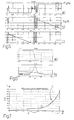
- figure 5 illustrates the time trend of the position x (t) of the swivel arm 4 (graph called “Position” and marked by letter “a”), the time trend of the current i (t) in a solenoid 8 (graph called “M1 current” and marked by the letter “b") and the time trend of the current i(t) in the other solenoid 8 (graph called "M2 current” and marked by the letter “c”).
- Figure 6 illustrates a detail of the graphs 5a and 5b (detail highlighted by a box in said graphs 5a and 5b).
- Figure 7 illustrates a magnetisation curve C of the iron part of a magnetic circuit 18 estimated by applying the above-described method.
- a solenoid 8 is powered by the control unit 11 with a relatively very high current i (t) to bring the swivel arm 4 to a stop against the respective magnetic core 16; initially the current i (t) is kept constant for a given time interval to annul any transients and subsequently said current is gradually reduced according to a decreasing slope with a relatively low inclination, i.e. variation in time, in order to substantially annul the influence of any dynamic effects.
- the magnetisation curve C of the iron part of the magnetic circuit 18 is reconstructed, determining for each current value i (t) (equal to the value of ampere turns divided by the number N of turns) the corresponding value of the flow ⁇ (t).
- the swivel'arm 4 detaches from the magnetic core 16 due to the elastic forces exerted by the spring 9 and the above-described operations can be repeated to identify the magnetisation curve C of the other solenoid 8.
- the lower end of the magnetisation curve C identified is defined by the detachment point D, which is diagnosed by identifying the slope variation of the curve of the current i (t) due to the counter electromotive effect induced by the movement of the swivel arm 4 in a magnetic field; the peak of the current i (t) following detachment of the swivel arm 4 is highlighted in figure 6.
- Precise identification of the detachment point D is extremely useful in flow control of the impact speed s (t) of the swivel arm 4, as it provides the value of the objective flow ⁇ (t) corresponding to the contact between the swivel arm 4 and the magnetic core 16.
- the magnetisation curve C is identified up to the detachment point D corresponding to a relatively low value of the holding flow ⁇ (t); to complete the magnetisation curve C for flow ⁇ (t) values below the holding value, it is possible to use a linear approximation defined by a straight line R joining detachment point D with the origin of the axes corresponding to a nil flow (the ferromagnetic materials used in construction of the magnetic cores 16 and in construction of the swivel arm 4 have a negligible residual magnetisation). This approximation is acceptable and introduces minimum errors, since for relatively low flow ⁇ (t) values, the magnetisation curve C has an almost linear trend.
- another more complex mathematical function can be used, for example a parabola, to approximate the trend of the magnetisation curve C; as an example, a condition of equality between the right and left derivatives of the magnetisation curve C corresponding to the detachment point D could be imposed.
- the elastic deformations are due to the fact that normally the faces of the magnetic cores 16 and of the swivel arm 4 are not perfectly in the same plane, therefore contact will not take place simultaneously on all the points of the facing surfaces, but only on a limited area.
- the force of attraction exerted on the swivel arm 4 increases; said increase in force causes an elastic deformation of the structure which tends to settle the facing surfaces, reducing the residual magnetic gap and, therefore, the overall reluctance R of the magnetic circuit 18 in those conditions.
- the above-described method for reconstruction of the magnetisation curve C allows us to explore and accurately trace the section of the magnetisation curve C corresponding to the beginning of the material saturation zone which, in the case of a non-uniform but laminate structure and non-isotropic material, can be dispersed from magnet to magnet. Note that it is particularly useful to know precisely the saturation condition of the solenoids 8 to ensure correct reconstruction of the position x (t) of the swivel arm 4 also in the presence of flows ⁇ (t) considerably higher than the saturation flow which can occur during the opening command of a discharge valve against high counter pressure forces of the burnt gases. Lastly, since the above-described method for estimating the magnetisation curve C can be repeated at the beginning of each work session, the variations in the system characteristics caused by ageing can be taken into consideration.
Landscapes
- Engineering & Computer Science (AREA)
- Mechanical Engineering (AREA)
- General Engineering & Computer Science (AREA)
- Magnetically Actuated Valves (AREA)
- Valve Device For Special Equipments (AREA)
- Electromagnets (AREA)
- Reciprocating, Oscillating Or Vibrating Motors (AREA)
Applications Claiming Priority (2)
| Application Number | Priority Date | Filing Date | Title |
|---|---|---|---|
| ITBO010077 | 2001-02-13 | ||
| IT2001BO000077A ITBO20010077A1 (it) | 2001-02-13 | 2001-02-13 | Metodo di stima della curva di magnetizzazione di un attuatore elettromagnetico per il comando di una valvola di un motore |
Publications (3)
| Publication Number | Publication Date |
|---|---|
| EP1231361A2 true EP1231361A2 (fr) | 2002-08-14 |
| EP1231361A3 EP1231361A3 (fr) | 2003-01-08 |
| EP1231361B1 EP1231361B1 (fr) | 2004-05-12 |
Family
ID=11439091
Family Applications (1)
| Application Number | Title | Priority Date | Filing Date |
|---|---|---|---|
| EP02003066A Expired - Lifetime EP1231361B1 (fr) | 2001-02-13 | 2002-02-12 | Procédé d'estimation de la courbe de magnétisation d'un actionneur électromagnétique de soupape |
Country Status (6)
| Country | Link |
|---|---|
| US (1) | US20020163329A1 (fr) |
| EP (1) | EP1231361B1 (fr) |
| BR (1) | BR0200427A (fr) |
| DE (1) | DE60200453T2 (fr) |
| ES (1) | ES2219590T3 (fr) |
| IT (1) | ITBO20010077A1 (fr) |
Families Citing this family (6)
| Publication number | Priority date | Publication date | Assignee | Title |
|---|---|---|---|---|
| US7255073B2 (en) * | 2003-10-14 | 2007-08-14 | Visteon Global Technologies, Inc. | Electromechanical valve actuator beginning of stroke damper |
| US7089895B2 (en) * | 2005-01-13 | 2006-08-15 | Motorola, Inc. | Valve operation in an internal combustion engine |
| US7305942B2 (en) * | 2005-02-23 | 2007-12-11 | Visteon Global Technologies, Inc. | Electromechanical valve actuator |
| CN100377913C (zh) * | 2005-04-29 | 2008-04-02 | 李岭群 | 一种永磁悬浮装置 |
| CN100377914C (zh) * | 2005-04-29 | 2008-04-02 | 李岭群 | 一种永磁悬浮装置 |
| US20250364168A1 (en) * | 2024-05-24 | 2025-11-27 | Rivian Ip Holdings, Llc | Solenoid position sensing |
Family Cites Families (8)
| Publication number | Priority date | Publication date | Assignee | Title |
|---|---|---|---|---|
| DE3817770A1 (de) * | 1988-05-26 | 1989-11-30 | Daimler Benz Ag | Einrichtung zur getakteten ansteuerung eines elektromagnetischen ventils |
| DE19544207C2 (de) * | 1995-11-28 | 2001-03-01 | Univ Dresden Tech | Verfahren zur modellbasierten Messung und Regelung von Bewegungen an elektromagnetischen Aktoren |
| US6176208B1 (en) * | 1997-07-03 | 2001-01-23 | Nippon Soken, Inc. | Electromagnetic valve driving apparatus |
| US5991143A (en) * | 1998-04-28 | 1999-11-23 | Siemens Automotive Corporation | Method for controlling velocity of an armature of an electromagnetic actuator |
| US6359435B1 (en) * | 1999-03-25 | 2002-03-19 | Siemens Automotive Corporation | Method for determining magnetic characteristics of an electronically controlled solenoid |
| IT1311131B1 (it) * | 1999-11-05 | 2002-03-04 | Magneti Marelli Spa | Metodo per il controllo di attuatori elettromagnetici perl'azionamento di valvole di aspirazione e scarico in motori a |
| IT1321182B1 (it) * | 2000-05-04 | 2003-12-30 | Magneti Marelli Spa | Metodo e dispositivo per la stima del flusso magnetico in unazionatore elettromagnetico per il comando di una valvola di un motore |
| DE10035759A1 (de) * | 2000-07-22 | 2002-01-31 | Daimler Chrysler Ag | Elektromagnetischer Aktuator zur Betätigung eines Gaswechselventils einer Brennkraftmaschine |
-
2001
- 2001-02-13 IT IT2001BO000077A patent/ITBO20010077A1/it unknown
-
2002
- 2002-02-12 EP EP02003066A patent/EP1231361B1/fr not_active Expired - Lifetime
- 2002-02-12 DE DE60200453T patent/DE60200453T2/de not_active Expired - Lifetime
- 2002-02-12 ES ES02003066T patent/ES2219590T3/es not_active Expired - Lifetime
- 2002-02-13 US US10/073,258 patent/US20020163329A1/en not_active Abandoned
- 2002-02-13 BR BR0200427-5A patent/BR0200427A/pt not_active Application Discontinuation
Also Published As
| Publication number | Publication date |
|---|---|
| ITBO20010077A0 (it) | 2001-02-13 |
| ITBO20010077A1 (it) | 2002-08-13 |
| US20020163329A1 (en) | 2002-11-07 |
| ES2219590T3 (es) | 2004-12-01 |
| EP1231361B1 (fr) | 2004-05-12 |
| DE60200453D1 (de) | 2004-06-17 |
| DE60200453T2 (de) | 2005-05-25 |
| BR0200427A (pt) | 2002-10-29 |
| EP1231361A3 (fr) | 2003-01-08 |
Similar Documents
| Publication | Publication Date | Title |
|---|---|---|
| EP1152129B1 (fr) | Procédé et dispositif pour déterminer la position de l'armature d'un actionneur électromagnétique pour contrôler une soupape de moteur | |
| Eyabi et al. | Modeling and sensorless control of an electromagnetic valve actuator | |
| EP0959479A2 (fr) | Procédé de régulation pour la vitesse de l'armature d'un actionneur électromagnétique | |
| CN103502615B (zh) | 识别具有线圈驱动机构的阀的关闭时间点的方法和该阀 | |
| US6683775B2 (en) | Control method for an electromagnetic actuator for the control of an engine valve | |
| Ramirez-Laboreo et al. | Real-time electromagnetic estimation for reluctance actuators | |
| EP1231361B1 (fr) | Procédé d'estimation de la courbe de magnétisation d'un actionneur électromagnétique de soupape | |
| JPH05243041A (ja) | 電磁弁可動子の機械的な運動を測定する方法 | |
| Zhong et al. | A vibration-based measurement method for dynamic characteristic of solenoid switching valve | |
| EP1205642B1 (fr) | Procédé d'estimation de l'effet du courant parasitaire dans un actionneur électromagnétique pour le contrôle d'une valve de moteur | |
| Kajima | Dynamic model of the plunger type solenoids at deenergizing state | |
| EP1152251B1 (fr) | Procédé et dispositif d'estimation d'un flux magnétique dans un actionneur électromagnétique de commande d'une soupape de moteur à combustion interne | |
| US6659422B2 (en) | Control method for an electromagnetic actuator for the control of a valve of an engine from a rest condition | |
| EP1319807B1 (fr) | Méthode pour estimer la position et la vitesse d'une armature d'un actionneur électromagnétique pour la commande d'une soupape de moteur | |
| KR20040040974A (ko) | 마그네토스트릭션 센서를 이용한 굽힘파 및 굽힘진동 측정장치및 방법 | |
| EP1271570B1 (fr) | Commande d'un actionneur électromagnétique de soupape de moteur depuis une position en butée | |
| Spekreijse et al. | Impact Solenoid Modelling for Current-Dependent Piston Position Estimation | |
| Xin et al. | Development of the permanent magnetic actuator with intelligent controlling system | |
| Gadyuchko et al. | Intrinsic sensor properties of solenoid actuators for fluid power | |
| Mahajan et al. | Performance analysis and experimental verification of solenoid actuator | |
| JP2003284369A (ja) | Emvaアマチュアの位置および速度を推定する方法 | |
| Choi et al. | Simulation of a Single Motor of Latch Type Control Element Drive Mechanism for Korean Next Generation Reactor | |
| Jurcik et al. | ANALYSIS OF GASOLINE INJECTION SYSTEM |
Legal Events
| Date | Code | Title | Description |
|---|---|---|---|
| PUAI | Public reference made under article 153(3) epc to a published international application that has entered the european phase |
Free format text: ORIGINAL CODE: 0009012 |
|
| AK | Designated contracting states |
Kind code of ref document: A2 Designated state(s): AT BE CH CY DE DK ES FI FR GB GR IE IT LI LU MC NL PT SE TR |
|
| AX | Request for extension of the european patent |
Free format text: AL;LT;LV;MK;RO;SI |
|
| PUAL | Search report despatched |
Free format text: ORIGINAL CODE: 0009013 |
|
| AK | Designated contracting states |
Kind code of ref document: A3 Designated state(s): AT BE CH CY DE DK ES FI FR GB GR IE IT LI LU MC NL PT SE TR |
|
| AX | Request for extension of the european patent |
Free format text: AL;LT;LV;MK;RO;SI |
|
| 17P | Request for examination filed |
Effective date: 20030707 |
|
| AKX | Designation fees paid |
Designated state(s): DE ES FR GB SE |
|
| GRAP | Despatch of communication of intention to grant a patent |
Free format text: ORIGINAL CODE: EPIDOSNIGR1 |
|
| GRAS | Grant fee paid |
Free format text: ORIGINAL CODE: EPIDOSNIGR3 |
|
| GRAA | (expected) grant |
Free format text: ORIGINAL CODE: 0009210 |
|
| AK | Designated contracting states |
Kind code of ref document: B1 Designated state(s): DE ES FR GB SE |
|
| RAP1 | Party data changed (applicant data changed or rights of an application transferred) |
Owner name: MAGNETI MARELLI POWERTRAIN S.P.A. |
|
| REG | Reference to a national code |
Ref country code: GB Ref legal event code: FG4D |
|
| RIN1 | Information on inventor provided before grant (corrected) |
Inventor name: MORSELLI, MICHELE Inventor name: D'ALPAOS, EGIDIO Inventor name: D'ANTONIO, FLAVIA |
|
| REG | Reference to a national code |
Ref country code: IE Ref legal event code: FG4D |
|
| REF | Corresponds to: |
Ref document number: 60200453 Country of ref document: DE Date of ref document: 20040617 Kind code of ref document: P |
|
| REG | Reference to a national code |
Ref country code: SE Ref legal event code: TRGR |
|
| REG | Reference to a national code |
Ref country code: ES Ref legal event code: FG2A Ref document number: 2219590 Country of ref document: ES Kind code of ref document: T3 |
|
| ET | Fr: translation filed | ||
| PLBE | No opposition filed within time limit |
Free format text: ORIGINAL CODE: 0009261 |
|
| STAA | Information on the status of an ep patent application or granted ep patent |
Free format text: STATUS: NO OPPOSITION FILED WITHIN TIME LIMIT |
|
| 26N | No opposition filed |
Effective date: 20050215 |
|
| PGFP | Annual fee paid to national office [announced via postgrant information from national office to epo] |
Ref country code: SE Payment date: 20091228 Year of fee payment: 9 |
|
| PGFP | Annual fee paid to national office [announced via postgrant information from national office to epo] |
Ref country code: ES Payment date: 20100205 Year of fee payment: 9 |
|
| PGFP | Annual fee paid to national office [announced via postgrant information from national office to epo] |
Ref country code: GB Payment date: 20100128 Year of fee payment: 9 |
|
| REG | Reference to a national code |
Ref country code: SE Ref legal event code: EUG |
|
| GBPC | Gb: european patent ceased through non-payment of renewal fee |
Effective date: 20110212 |
|
| PG25 | Lapsed in a contracting state [announced via postgrant information from national office to epo] |
Ref country code: GB Free format text: LAPSE BECAUSE OF NON-PAYMENT OF DUE FEES Effective date: 20110212 |
|
| REG | Reference to a national code |
Ref country code: ES Ref legal event code: FD2A Effective date: 20120411 |
|
| PG25 | Lapsed in a contracting state [announced via postgrant information from national office to epo] |
Ref country code: ES Free format text: LAPSE BECAUSE OF NON-PAYMENT OF DUE FEES Effective date: 20110213 |
|
| PG25 | Lapsed in a contracting state [announced via postgrant information from national office to epo] |
Ref country code: SE Free format text: LAPSE BECAUSE OF NON-PAYMENT OF DUE FEES Effective date: 20110213 |
|
| REG | Reference to a national code |
Ref country code: FR Ref legal event code: PLFP Year of fee payment: 15 |
|
| REG | Reference to a national code |
Ref country code: FR Ref legal event code: PLFP Year of fee payment: 16 |
|
| REG | Reference to a national code |
Ref country code: FR Ref legal event code: PLFP Year of fee payment: 17 |
|
| PGFP | Annual fee paid to national office [announced via postgrant information from national office to epo] |
Ref country code: FR Payment date: 20190123 Year of fee payment: 18 Ref country code: DE Payment date: 20190122 Year of fee payment: 18 |
|
| REG | Reference to a national code |
Ref country code: DE Ref legal event code: R119 Ref document number: 60200453 Country of ref document: DE |
|
| PG25 | Lapsed in a contracting state [announced via postgrant information from national office to epo] |
Ref country code: FR Free format text: LAPSE BECAUSE OF NON-PAYMENT OF DUE FEES Effective date: 20200229 Ref country code: DE Free format text: LAPSE BECAUSE OF NON-PAYMENT OF DUE FEES Effective date: 20200901 |