EP1231377A2 - Filtre pour liquides, en particulier carburants - Google Patents
Filtre pour liquides, en particulier carburants Download PDFInfo
- Publication number
- EP1231377A2 EP1231377A2 EP02002803A EP02002803A EP1231377A2 EP 1231377 A2 EP1231377 A2 EP 1231377A2 EP 02002803 A EP02002803 A EP 02002803A EP 02002803 A EP02002803 A EP 02002803A EP 1231377 A2 EP1231377 A2 EP 1231377A2
- Authority
- EP
- European Patent Office
- Prior art keywords
- filter
- fabric
- tubular body
- inlet opening
- filter according
- Prior art date
- Legal status (The legal status is an assumption and is not a legal conclusion. Google has not performed a legal analysis and makes no representation as to the accuracy of the status listed.)
- Granted
Links
- 239000000446 fuel Substances 0.000 title claims description 10
- 239000007788 liquid Substances 0.000 title claims description 4
- 239000004744 fabric Substances 0.000 claims abstract description 39
- 230000002787 reinforcement Effects 0.000 claims description 4
- 238000003466 welding Methods 0.000 claims description 3
- 238000004519 manufacturing process Methods 0.000 description 6
- 238000010276 construction Methods 0.000 description 5
- 239000002828 fuel tank Substances 0.000 description 2
- 238000009434 installation Methods 0.000 description 2
- 238000002347 injection Methods 0.000 description 1
- 239000007924 injection Substances 0.000 description 1
- 239000002184 metal Substances 0.000 description 1
Images

Classifications
-
- B—PERFORMING OPERATIONS; TRANSPORTING
- B01—PHYSICAL OR CHEMICAL PROCESSES OR APPARATUS IN GENERAL
- B01D—SEPARATION
- B01D35/00—Filtering devices having features not specifically covered by groups B01D24/00 - B01D33/00, or for applications not specifically covered by groups B01D24/00 - B01D33/00; Auxiliary devices for filtration; Filter housing constructions
- B01D35/02—Filters adapted for location in special places, e.g. pipe-lines, pumps, stop-cocks
- B01D35/027—Filters adapted for location in special places, e.g. pipe-lines, pumps, stop-cocks rigidly mounted in or on tanks or reservoirs
- B01D35/0273—Filtering elements with a horizontal or inclined rotation or symmetry axis submerged in tanks or reservoirs
-
- B—PERFORMING OPERATIONS; TRANSPORTING
- B01—PHYSICAL OR CHEMICAL PROCESSES OR APPARATUS IN GENERAL
- B01D—SEPARATION
- B01D35/00—Filtering devices having features not specifically covered by groups B01D24/00 - B01D33/00, or for applications not specifically covered by groups B01D24/00 - B01D33/00; Auxiliary devices for filtration; Filter housing constructions
- B01D35/02—Filters adapted for location in special places, e.g. pipe-lines, pumps, stop-cocks
- B01D35/027—Filters adapted for location in special places, e.g. pipe-lines, pumps, stop-cocks rigidly mounted in or on tanks or reservoirs
-
- B—PERFORMING OPERATIONS; TRANSPORTING
- B01—PHYSICAL OR CHEMICAL PROCESSES OR APPARATUS IN GENERAL
- B01D—SEPARATION
- B01D35/00—Filtering devices having features not specifically covered by groups B01D24/00 - B01D33/00, or for applications not specifically covered by groups B01D24/00 - B01D33/00; Auxiliary devices for filtration; Filter housing constructions
- B01D35/30—Filter housing constructions
-
- F—MECHANICAL ENGINEERING; LIGHTING; HEATING; WEAPONS; BLASTING
- F02—COMBUSTION ENGINES; HOT-GAS OR COMBUSTION-PRODUCT ENGINE PLANTS
- F02M—SUPPLYING COMBUSTION ENGINES IN GENERAL WITH COMBUSTIBLE MIXTURES OR CONSTITUENTS THEREOF
- F02M37/00—Apparatus or systems for feeding liquid fuel from storage containers to carburettors or fuel-injection apparatus; Arrangements for purifying liquid fuel specially adapted for, or arranged on, internal-combustion engines
- F02M37/22—Arrangements for purifying liquid fuel specially adapted for, or arranged on, internal-combustion engines, e.g. arrangements in the feeding system
- F02M37/32—Arrangements for purifying liquid fuel specially adapted for, or arranged on, internal-combustion engines, e.g. arrangements in the feeding system characterised by filters or filter arrangements
- F02M37/50—Filters arranged in or on fuel tanks
-
- B—PERFORMING OPERATIONS; TRANSPORTING
- B01—PHYSICAL OR CHEMICAL PROCESSES OR APPARATUS IN GENERAL
- B01D—SEPARATION
- B01D2201/00—Details relating to filtering apparatus
- B01D2201/40—Special measures for connecting different parts of the filter
- B01D2201/4023—Means for connecting filter housings to supports
Definitions
- the invention relates to a filter for liquids, in particular Fuels, with a plastic one Support body, which supports a plastic fabric and this serves the opposite sides of the through the Filter fabric formed filter body at a distance from each other to hold, and with one on the outside of the filter body arranged pump connector, which inside the Filter body has an inlet opening, the support body is completely enclosed by filter fabric and only via the inlet opening and the pump connector has a connection to the outside, and wherein the filter one first part containing the pump connection piece and at least one arranged at an angle to the first part second part.
- a filter of this type is, according to an earlier proposal Applicant known from DE-Gbm 298 12 483.
- Filters form the first part and the second part together the filter body, the two parts by means of a Hinge or joint are interconnected, by means of the second part of which is common to the first part with the filter fabric from a straight beveled initial shape of the two parts foldable into an angular position and by means of a locking device in the angular position is fixable.
- Filters of this type are said to be special have simple construction and are as a fuel filter especially for installation in a fuel tank provided by vehicles.
- the filter function is here taken over by the filter fabric, the support body serves the opposite sides of the through the filter body formed filter body at a distance from each other to hold, since otherwise both sides partially against each other could adhere, causing the available filter area would be reduced.
- the support body serves the opposite sides of the through the filter body formed filter body at a distance from each other to hold, since otherwise both sides partially against each other could adhere, causing the available filter area would be reduced.
- This task is carried out with a filter of the type mentioned kind essentially solved by having the first part through a tubular body is formed, which at its first end arranged approximately at right angles to the main axis of the tubular body Has pump connection piece, and which one its second end with the axially extending inlet opening is provided that the tubular body of the pump connection piece opposite is an intake opening covered by filter fabric has that of the support body and the filter fabric existing filter body the second part of the filter forms, and that the filter body in the selected angular position is firmly connected to the tubular body.
- a two-part design was chosen by the first part is formed by a simple tubular body, which is fixed with the actual filter body, which is the second part of the filter forms in a according to the installation requirements selected angular position is connected. Still enables the simple tubular body allows for almost complete emptying the tank by placing the one opposite the pump connector Intake opening with the filter fabric fastened in it also takes over part of the filter function. About that is also through this additional suction opening The suction path of the filter is reduced to almost a quarter, which means For example, an engine is even faster in the starting phase can start. This also offers an additional suction opening the advantage of the tank capacity up to the level of this To be able to empty the suction opening.
- the suction opening has at least the cross section of the pump connection piece on. This will make it more streamlined Conditions created from the suction opening to the pump.
- tubular body has a rectangular cross section has what is the advantage of a simple design of the pump connector and a flat filter surface in the suction opening.
- the support body is on the filter fabric forming the one side of the filter body is injected. This will simplify manufacturing of the filter possible.
- this is the other side of the filter body forming filter fabric only over a circumference of the filter body partially or completely forming Weld with that forming the one side of the filter body Filter fabric is connected. This is another Simplification of the manufacturing process possible.
- a particularly preferred embodiment according to the invention can be created in that the tubular body on the Inlet opening has a reinforcement surrounding it, which forms an inner shoulder, and that there is a connector supports the filter body on the inner shoulder in such a way that the flow cross section in the inlet opening remains unchanged remains.
- connection part at the inlet opening of the tubular body by ultrasonic welding or the like is permanently attached.
- the outer one The inside edge of the inlet opening preferably has an inlet slope on.
- Another, particularly preferred embodiment according to the Invention can be created in that in addition to the pump connection piece on the outside of the tubular body Clamping device for attaching the filter to the suction side a pump is provided.
- This clamping device preferably consists of one piece lateral approach of the tubular body and is also particular through an apron looking down surrounding elongated hole formed, the apron a slight Tapered.
- the taper is preferably about 3 °.
- This preferred Embodiment of the clamping device offers the advantage that this fixes the filter to the suction side a pump compared to the prior art significantly can be simplified by since the tubular body with the approach consists of a single piece of plastic, the resilient properties the tapered apron is enough to cover the Filters securely to the pump port on the suction side of the Attach the pump by simply pulling the slot over one Mandrel or the like is pushed on the pump.
- Constructions previously required a bag train in which a metal clip has been inserted, which continues through an additional work step against falling out had to be secured.
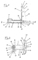
- the filter 1 for liquids shown in the drawings, in particular fuels, consists of all individual parts a plastic suitable for this purpose.
- the filter 1 contains a support body 4, which is a plastic fabric or Filter fabric 6 supports to the opposite Pages 8 and 10 one formed by the filter fabric 6 Keeps the filter body apart from each other to prevent that the filter 1 collapses in operation.
- the support body 4 is completely enclosed by the filter fabric 6 and is only on the inlet opening 16 and the pump connection piece 14 with the outside of the filter 1 in connection.
- the filter 1 is made of two, in the embodiment Parts 18 and 20 at right angles to each other constructed, the first part 18 the pump connection piece 14 and the second part 20 contains the support body 4.
- the first part 18 is in one piece with the pump connector 14 formed tubular body 22nd educated.
- the tubular body 22 has, as can be seen from the view 3 shows a rectangular cross section.
- On its first end 24 of the tubular body 22 is approximately in right angle to the main axis of the tubular body 22 standing Pump connector 14 formed.
- At its second end 26 is the tubular body 22 with the axially extending inlet opening 16 provided on which, as further below is explained, the filter body 12 is attached.
- the tubular body 22 is the pump connection piece 14 directly provided with a suction opening 28 opposite, which is covered by filter fabric 30.
- the suction opening 28 can have any shape, but is in In the present case, it is also expedient to have a circular shape corresponding to the cross section of the pump connector 14 formed and preferably has at least the same cross section as the pump connector 14 on.
- the illustrated embodiment is consequently that which forms the other side 8 of the filter body 12 Filter fabric 6 only over the three side edges of the filter body 12 circumferential weld 13 with the opposite Page 10 of the filter body 12 forming filter fabric 6 connected.
- the inner shoulder 34 is supported a connecting part 36 of the filter body 12, which with the Support body 4 formed in one piece and also to the Injection molded side 10 of the filter fabric 6 of the filter body 12 is.
- the dimensions are chosen such that the Connection between the connecting part 36 and the tubular body 22nd is such that the flow cross section in the inlet opening 16 remains unchanged.
- the connecting part 36 is at the inlet opening 16 of the tubular body 22 by ultrasonic welding or equivalent permanently attached.
- the desired angular position between the first part 18 and the second part 20 of the filter 1 consequently by appropriate design of the connecting part 36 during manufacture according to the geometry of the intended Location of filter 1 selected.
- the outer inner edge is also 38 of the inlet opening 36 is provided with an inlet slope 40.
- a specially designed clamping device 42 is provided, which in a one-piece side extension 44 of the Tubular body 22 is formed.
- the clamping device 42 is made from an apron 48 pointing downwards surrounding slot 46, the apron 48 has a low taper downward, which in the embodiment is about 3 °.
- Will the elongated hole 46 with the apron 48 a mandrel provided on the fuel delivery device put on, so is the taper of the apron 48 extremely secure, frictional connection in the simplest Manufactured way. Since such filters in practice Use one unit with the fuel delivery system form, which inside a likewise not shown Fuel tank of the motor vehicle arranged such a secure connection represents a significant one Advantage.
Landscapes
- Chemical & Material Sciences (AREA)
- Chemical Kinetics & Catalysis (AREA)
- Engineering & Computer Science (AREA)
- Combustion & Propulsion (AREA)
- Mechanical Engineering (AREA)
- General Engineering & Computer Science (AREA)
- Filtration Of Liquid (AREA)
- Details Of Reciprocating Pumps (AREA)
- Cooling, Air Intake And Gas Exhaust, And Fuel Tank Arrangements In Propulsion Units (AREA)
- Filtering Materials (AREA)
Applications Claiming Priority (2)
| Application Number | Priority Date | Filing Date | Title |
|---|---|---|---|
| DE20102217U DE20102217U1 (de) | 2001-02-08 | 2001-02-08 | Filter für Flüssigkeiten, insbesondere Kraftstoffe |
| DE20102217U | 2001-02-08 |
Publications (4)
| Publication Number | Publication Date |
|---|---|
| EP1231377A2 true EP1231377A2 (fr) | 2002-08-14 |
| EP1231377A3 EP1231377A3 (fr) | 2003-12-03 |
| EP1231377B1 EP1231377B1 (fr) | 2005-04-27 |
| EP1231377B9 EP1231377B9 (fr) | 2005-07-13 |
Family
ID=7952711
Family Applications (1)
| Application Number | Title | Priority Date | Filing Date |
|---|---|---|---|
| EP02002803A Expired - Lifetime EP1231377B9 (fr) | 2001-02-08 | 2002-02-07 | Filtre pour liquides, en particulier carburants |
Country Status (5)
| Country | Link |
|---|---|
| US (1) | US6736273B2 (fr) |
| EP (1) | EP1231377B9 (fr) |
| BR (1) | BR0201272B1 (fr) |
| CA (1) | CA2370779C (fr) |
| DE (2) | DE20102217U1 (fr) |
Cited By (1)
| Publication number | Priority date | Publication date | Assignee | Title |
|---|---|---|---|---|
| WO2009043764A1 (fr) * | 2007-09-26 | 2009-04-09 | Continental Automotive Gmbh | Conduit de liquide à optimisation acoustique |
Families Citing this family (7)
| Publication number | Priority date | Publication date | Assignee | Title |
|---|---|---|---|---|
| US20070151920A1 (en) * | 2005-12-06 | 2007-07-05 | Kay Ronald J | System and method of micromolded filtration microstructure and devices |
| JP2008255843A (ja) * | 2007-04-03 | 2008-10-23 | Kawasaki Heavy Ind Ltd | 車輌用燃料供給システム及びこれを備えた不整地用四輪走行車 |
| JP2010019151A (ja) * | 2008-07-10 | 2010-01-28 | Nifco Inc | 燃料用フィルタ |
| CN103635243B (zh) * | 2011-03-29 | 2016-06-08 | 酷思滤清系统有限公司 | 具有塑料保持器的箱内流体过滤器 |
| US8372278B1 (en) * | 2012-03-21 | 2013-02-12 | GM Global Technology Operations LLC | Liquid fuel strainer assembly |
| DE102013001237B4 (de) * | 2013-01-25 | 2015-04-16 | Kautex Textron Gmbh & Co. Kg | Filtervorrichtung für einen Flüssigkeitsbehälter, insbesondere für wässrige Harnstofflösung |
| KR102178858B1 (ko) * | 2019-09-25 | 2020-11-13 | 주식회사 코아비스 | 연료펌프용 스트레이너 |
Citations (1)
| Publication number | Priority date | Publication date | Assignee | Title |
|---|---|---|---|---|
| DE29812483U1 (de) | 1998-07-16 | 1998-10-01 | Filtertek, S.A., Plailly | Filter für Flüssigkeiten |
Family Cites Families (37)
| Publication number | Priority date | Publication date | Assignee | Title |
|---|---|---|---|---|
| US1235438A (en) | 1916-10-24 | 1917-07-31 | Henry William Chynoweth | Gasolene tank and filter. |
| DE925712C (de) | 1941-12-19 | 1955-03-28 | Seitz Werke Gmbh | Tragbares Kleinfiltergeraet |
| US2381949A (en) | 1944-08-17 | 1945-08-14 | Metal Textile Corp | Means for detachably mounting strainer bags |
| DE814362C (de) | 1949-10-14 | 1951-09-20 | Ernst Kreissig | Gummistahlfeder |
| US3826372A (en) | 1973-06-14 | 1974-07-30 | Kuss R & Co Inc | Flexible filter |
| DE2658358C3 (de) | 1976-12-23 | 1979-11-29 | Volkswagenwerk Ag, 3180 Wolfsburg | Schallisolierende Aufhängung für eine Leitung, insbesondere eine Abgasleitung |
| US4077887A (en) | 1977-05-17 | 1978-03-07 | Sigmund Coll Langvik | Filter disc for vacuum filter system |
| US4159951A (en) | 1978-01-25 | 1979-07-03 | Envirotech Corporation | Sector assembly |
| US4312753A (en) | 1980-01-17 | 1982-01-26 | Bell Steven L | Intank fuel filter |
| JPS57184408A (en) | 1981-05-08 | 1982-11-13 | Jidosha Denki Kogyo Co Ltd | Filter for fuel tank |
| JPS59162354A (ja) | 1983-03-08 | 1984-09-13 | Nissan Motor Co Ltd | 燃料フイルタ− |
| JPS59199324A (ja) | 1983-04-25 | 1984-11-12 | Nissan Motor Co Ltd | 燃料タンクのフイルタ−装置 |
| US4772044A (en) | 1983-08-22 | 1988-09-20 | Booher Benjamin V | Vehicle suspension system with flexible control arm |
| JPS6151471U (fr) * | 1984-09-10 | 1986-04-07 | ||
| JPS6241962A (ja) | 1985-08-15 | 1987-02-23 | Nissan Motor Co Ltd | 燃料タンクのフイ−ドポンプ取付構造 |
| JPH0773643B2 (ja) | 1986-01-17 | 1995-08-09 | 株式会社ニフコ | 燃料タンクのフイルタ− |
| JPH0244805Y2 (fr) | 1986-01-17 | 1990-11-28 | ||
| JPH0529134Y2 (fr) | 1986-08-01 | 1993-07-27 | ||
| JPH064888Y2 (ja) | 1987-05-15 | 1994-02-09 | 株式会社ニフコ | フィルタ |
| US5055187A (en) * | 1988-05-27 | 1991-10-08 | Kyosan Denki Kabushiki Kaisha | Fuel filter incorporated in a fuel tank |
| ATE81603T1 (de) | 1988-11-08 | 1992-11-15 | Filtertek Gmbh | Filter fuer fluessige kraftstoffe. |
| JPH02222705A (ja) | 1989-02-22 | 1990-09-05 | Mitsubishi Electric Corp | 燃料濾過器 |
| US5169531A (en) | 1989-02-22 | 1992-12-08 | Mitsubishi Denki Kabushiki Kaisha | Noise diffusing fuel filter |
| DE3914938C1 (en) | 1989-05-06 | 1990-10-11 | Bayerische Motoren Werke Ag, 8000 Muenchen, De | Fuel filter - comprising bag-shaped liq. permeable fabric structure with support member on inside |
| US5174841A (en) | 1989-05-09 | 1992-12-29 | Kuss Corporation | Method of making an in-tank fuel filter |
| US4961850A (en) | 1989-05-09 | 1990-10-09 | Kuss Corporation | In-tank fuel filter |
| ATE88245T1 (de) | 1989-05-30 | 1993-04-15 | Filtertek Gmbh | Verfahren zum herstellen eines filters fuer fluessige kraftstoffe. |
| US5049271A (en) | 1990-08-27 | 1991-09-17 | Filtertek, Inc. | Fuel tank filter |
| DE4102474A1 (de) | 1991-01-29 | 1992-08-06 | Filtertek Gmbh | Filter fuer fluessigkeiten, insbesondere fuer kraftstoffe |
| DE69217451T2 (de) | 1991-11-12 | 1997-09-04 | Filtertek Inc | Filter für Kraftstoffbehälter |
| JP3353986B2 (ja) | 1993-10-04 | 2002-12-09 | 株式会社ニフコ | 燃料用フィルター |
| US5665229A (en) * | 1995-07-07 | 1997-09-09 | Kuss Corporation | In-tank fuel filter with floating mounting |
| DE29518501U1 (de) | 1995-11-23 | 1996-02-01 | Filtertek, S.A., Plailly | Vorrichtung zum Verbinden des Ansaugstutzens einer Kraftstoffpumpe mit einem aus Kunststoff bestehenden Kraftstoffilter |
| DE29609750U1 (de) | 1996-06-04 | 1996-11-28 | Filtertek, S.A., Plailly | Kraftstoff-Filter |
| US5795468A (en) * | 1997-03-31 | 1998-08-18 | Ford Motor Company | In-tank automotive fuel filter |
| US5876599A (en) * | 1997-04-07 | 1999-03-02 | Kuss Corporation | Compact in-tank fuel filter and module |
| US6176133B1 (en) * | 1999-03-08 | 2001-01-23 | Robert B. Hutter | Fuel sending unit having a fuel filter combined with a fuel float |
-
2001
- 2001-02-08 DE DE20102217U patent/DE20102217U1/de not_active Expired - Lifetime
-
2002
- 2002-02-07 DE DE50202877T patent/DE50202877D1/de not_active Expired - Lifetime
- 2002-02-07 EP EP02002803A patent/EP1231377B9/fr not_active Expired - Lifetime
- 2002-02-08 CA CA002370779A patent/CA2370779C/fr not_active Expired - Fee Related
- 2002-02-08 US US10/071,865 patent/US6736273B2/en not_active Expired - Lifetime
- 2002-02-08 BR BRPI0201272-3A patent/BR0201272B1/pt not_active IP Right Cessation
Patent Citations (1)
| Publication number | Priority date | Publication date | Assignee | Title |
|---|---|---|---|---|
| DE29812483U1 (de) | 1998-07-16 | 1998-10-01 | Filtertek, S.A., Plailly | Filter für Flüssigkeiten |
Cited By (3)
| Publication number | Priority date | Publication date | Assignee | Title |
|---|---|---|---|---|
| WO2009043764A1 (fr) * | 2007-09-26 | 2009-04-09 | Continental Automotive Gmbh | Conduit de liquide à optimisation acoustique |
| CN101809275B (zh) * | 2007-09-26 | 2013-07-31 | 大陆汽车有限责任公司 | 声音优化的流体管道 |
| KR101493547B1 (ko) * | 2007-09-26 | 2015-02-13 | 콘티넨탈 오토모티브 게엠베하 | 음향적으로 최적화된 유체 라인 |
Also Published As
| Publication number | Publication date |
|---|---|
| US20020162790A1 (en) | 2002-11-07 |
| DE50202877D1 (de) | 2005-06-02 |
| CA2370779A1 (fr) | 2002-08-08 |
| BR0201272B1 (pt) | 2011-01-25 |
| EP1231377B9 (fr) | 2005-07-13 |
| US6736273B2 (en) | 2004-05-18 |
| CA2370779C (fr) | 2005-06-21 |
| EP1231377B1 (fr) | 2005-04-27 |
| EP1231377A3 (fr) | 2003-12-03 |
| DE20102217U1 (de) | 2001-06-13 |
| BR0201272A (pt) | 2002-10-01 |
Similar Documents
| Publication | Publication Date | Title |
|---|---|---|
| DE19600980B4 (de) | Brennstoff-Tank-Filter mit Halterung | |
| EP2399019B1 (fr) | Séparateur d'eau, en particulier pour systèmes d'alimentation en carburant de moteurs à combustion interne dans des véhicules à moteur | |
| DE2723771C3 (de) | Behälteranordnung, insbesondere Kraftstoff-Behälteranordnung für ein Kraftfahrzeug | |
| DE69200117T2 (de) | Lenksäulenrohr und Gehäuse für Kraftfahrzeug. | |
| EP0612944A1 (fr) | Elément de fixation monobloc | |
| DE2936318B2 (de) | Behälter, insbesondere Kraftstoffbehälter für Kraftfahrzeuge | |
| DE69504469T2 (de) | Verbesserungen in vibrationsdämpfenden hydraulischen Stützen | |
| DE3843659A1 (de) | Anschlussvorrichtung fuer einspritzduesen | |
| DE102005045442A1 (de) | Anordnung bestehend aus einem Zapfmodul und einem Zubehörteil, welche in einen Kraftstofftank für ein Kraftfahrzeug einsetzbar ist | |
| EP1231377B9 (fr) | Filtre pour liquides, en particulier carburants | |
| DE29812483U1 (de) | Filter für Flüssigkeiten | |
| DE69612351T2 (de) | Vorrichtung für die Aufhängung einer Pumpe und/oder Sieb zur Pumpeneinheit gehörend | |
| DE10328456A1 (de) | Vorrichtung zur Befestigung eines Behälters zur Aufnahme von flüssigen Brennstoffen | |
| DE19943292C1 (de) | Endseitige Haltevorrichtung für eine Entlüftungsleitung eines Kraftstoffbehälters | |
| DE10023487A1 (de) | Befestigungssystem für Kunststoffteile | |
| DE29518501U1 (de) | Vorrichtung zum Verbinden des Ansaugstutzens einer Kraftstoffpumpe mit einem aus Kunststoff bestehenden Kraftstoffilter | |
| DE102020210818A1 (de) | Anordnung für ein Fahrzeug, Fahrzeug | |
| DE3730567C2 (de) | Flüssigkeitspumpe | |
| DE3320492C2 (fr) | ||
| EP1056625B1 (fr) | Dispositif d'entrainement pour essuie-glace | |
| DE3600134C1 (en) | Steering column tube for a steering column of motor vehicles | |
| DE19957967B4 (de) | Tankklappe aus Kunststoff für ein Kraftfahrzeug | |
| DE69404908T2 (de) | Scheibenwischer mit gelenkig verbundenen Elementen | |
| DE2758914B1 (fr) | ||
| DE9311357U1 (de) | Einrichtung zum Befestigen eines Flüssigkeitsfilters an einem Maschinenteil |
Legal Events
| Date | Code | Title | Description |
|---|---|---|---|
| PUAI | Public reference made under article 153(3) epc to a published international application that has entered the european phase |
Free format text: ORIGINAL CODE: 0009012 |
|
| AK | Designated contracting states |
Kind code of ref document: A2 Designated state(s): AT BE CH CY DE DK ES FI FR GB GR IE IT LI LU MC NL PT SE TR |
|
| AX | Request for extension of the european patent |
Free format text: AL;LT;LV;MK;RO;SI |
|
| PUAL | Search report despatched |
Free format text: ORIGINAL CODE: 0009013 |
|
| AK | Designated contracting states |
Kind code of ref document: A3 Designated state(s): AT BE CH CY DE DK ES FI FR GB GR IE IT LI LU MC NL PT SE TR |
|
| AX | Request for extension of the european patent |
Extension state: AL LT LV MK RO SI |
|
| RIC1 | Information provided on ipc code assigned before grant |
Ipc: 7B 01D 35/027 B Ipc: 7F 02M 37/22 A |
|
| 17P | Request for examination filed |
Effective date: 20040417 |
|
| GRAP | Despatch of communication of intention to grant a patent |
Free format text: ORIGINAL CODE: EPIDOSNIGR1 |
|
| AKX | Designation fees paid |
Designated state(s): DE FR GB IT |
|
| GRAS | Grant fee paid |
Free format text: ORIGINAL CODE: EPIDOSNIGR3 |
|
| GRAA | (expected) grant |
Free format text: ORIGINAL CODE: 0009210 |
|
| AK | Designated contracting states |
Kind code of ref document: B1 Designated state(s): DE FR GB IT |
|
| REG | Reference to a national code |
Ref country code: GB Ref legal event code: FG4D Free format text: NOT ENGLISH |
|
| REG | Reference to a national code |
Ref country code: IE Ref legal event code: FG4D Free format text: LANGUAGE OF EP DOCUMENT: GERMAN |
|
| REF | Corresponds to: |
Ref document number: 50202877 Country of ref document: DE Date of ref document: 20050602 Kind code of ref document: P |
|
| GBT | Gb: translation of ep patent filed (gb section 77(6)(a)/1977) |
Effective date: 20050616 |
|
| PLBE | No opposition filed within time limit |
Free format text: ORIGINAL CODE: 0009261 |
|
| STAA | Information on the status of an ep patent application or granted ep patent |
Free format text: STATUS: NO OPPOSITION FILED WITHIN TIME LIMIT |
|
| ET | Fr: translation filed | ||
| 26N | No opposition filed |
Effective date: 20060130 |
|
| PGFP | Annual fee paid to national office [announced via postgrant information from national office to epo] |
Ref country code: GB Payment date: 20110223 Year of fee payment: 10 |
|
| GBPC | Gb: european patent ceased through non-payment of renewal fee |
Effective date: 20120207 |
|
| PG25 | Lapsed in a contracting state [announced via postgrant information from national office to epo] |
Ref country code: GB Free format text: LAPSE BECAUSE OF NON-PAYMENT OF DUE FEES Effective date: 20120207 |
|
| REG | Reference to a national code |
Ref country code: FR Ref legal event code: PLFP Year of fee payment: 14 |
|
| PGFP | Annual fee paid to national office [announced via postgrant information from national office to epo] |
Ref country code: DE Payment date: 20150226 Year of fee payment: 14 Ref country code: IT Payment date: 20150220 Year of fee payment: 14 |
|
| PGFP | Annual fee paid to national office [announced via postgrant information from national office to epo] |
Ref country code: FR Payment date: 20150217 Year of fee payment: 14 |
|
| REG | Reference to a national code |
Ref country code: DE Ref legal event code: R082 Ref document number: 50202877 Country of ref document: DE Representative=s name: WEICKMANN & WEICKMANN PATENT- UND RECHTSANWAEL, DE Ref country code: DE Ref legal event code: R082 Ref document number: 50202877 Country of ref document: DE Representative=s name: WEICKMANN & WEICKMANN PATENTANWAELTE - RECHTSA, DE |
|
| REG | Reference to a national code |
Ref country code: DE Ref legal event code: R119 Ref document number: 50202877 Country of ref document: DE |
|
| REG | Reference to a national code |
Ref country code: FR Ref legal event code: ST Effective date: 20161028 |
|
| PG25 | Lapsed in a contracting state [announced via postgrant information from national office to epo] |
Ref country code: IT Free format text: LAPSE BECAUSE OF NON-PAYMENT OF DUE FEES Effective date: 20160207 |
|
| PG25 | Lapsed in a contracting state [announced via postgrant information from national office to epo] |
Ref country code: FR Free format text: LAPSE BECAUSE OF NON-PAYMENT OF DUE FEES Effective date: 20160229 Ref country code: DE Free format text: LAPSE BECAUSE OF NON-PAYMENT OF DUE FEES Effective date: 20160901 |