EP1233245A2 - Echangeurs de chaleur et méthodes de production de ces échangeurs - Google Patents
Echangeurs de chaleur et méthodes de production de ces échangeurs Download PDFInfo
- Publication number
- EP1233245A2 EP1233245A2 EP02250554A EP02250554A EP1233245A2 EP 1233245 A2 EP1233245 A2 EP 1233245A2 EP 02250554 A EP02250554 A EP 02250554A EP 02250554 A EP02250554 A EP 02250554A EP 1233245 A2 EP1233245 A2 EP 1233245A2
- Authority
- EP
- European Patent Office
- Prior art keywords
- resin
- heat exchanger
- aluminum
- aluminum members
- coated
- Prior art date
- Legal status (The legal status is an assumption and is not a legal conclusion. Google has not performed a legal analysis and makes no representation as to the accuracy of the status listed.)
- Withdrawn
Links
Images
Classifications
-
- F—MECHANICAL ENGINEERING; LIGHTING; HEATING; WEAPONS; BLASTING
- F28—HEAT EXCHANGE IN GENERAL
- F28F—DETAILS OF HEAT-EXCHANGE AND HEAT-TRANSFER APPARATUS, OF GENERAL APPLICATION
- F28F19/00—Preventing the formation of deposits or corrosion, e.g. by using filters or scrapers
- F28F19/02—Preventing the formation of deposits or corrosion, e.g. by using filters or scrapers by using coatings, e.g. vitreous or enamel coatings
- F28F19/04—Preventing the formation of deposits or corrosion, e.g. by using filters or scrapers by using coatings, e.g. vitreous or enamel coatings of rubber; of plastics material; of varnish
-
- F—MECHANICAL ENGINEERING; LIGHTING; HEATING; WEAPONS; BLASTING
- F28—HEAT EXCHANGE IN GENERAL
- F28D—HEAT-EXCHANGE APPARATUS, NOT PROVIDED FOR IN ANOTHER SUBCLASS, IN WHICH THE HEAT-EXCHANGE MEDIA DO NOT COME INTO DIRECT CONTACT
- F28D1/00—Heat-exchange apparatus having stationary conduit assemblies for one heat-exchange medium only, the media being in contact with different sides of the conduit wall, in which the other heat-exchange medium is a large body of fluid, e.g. domestic or motor car radiators
- F28D1/02—Heat-exchange apparatus having stationary conduit assemblies for one heat-exchange medium only, the media being in contact with different sides of the conduit wall, in which the other heat-exchange medium is a large body of fluid, e.g. domestic or motor car radiators with heat-exchange conduits immersed in the body of fluid
- F28D1/03—Heat-exchange apparatus having stationary conduit assemblies for one heat-exchange medium only, the media being in contact with different sides of the conduit wall, in which the other heat-exchange medium is a large body of fluid, e.g. domestic or motor car radiators with heat-exchange conduits immersed in the body of fluid with plate-like or laminated conduits
- F28D1/0308—Heat-exchange apparatus having stationary conduit assemblies for one heat-exchange medium only, the media being in contact with different sides of the conduit wall, in which the other heat-exchange medium is a large body of fluid, e.g. domestic or motor car radiators with heat-exchange conduits immersed in the body of fluid with plate-like or laminated conduits the conduits being formed by paired plates touching each other
- F28D1/0316—Assemblies of conduits in parallel
-
- F—MECHANICAL ENGINEERING; LIGHTING; HEATING; WEAPONS; BLASTING
- F28—HEAT EXCHANGE IN GENERAL
- F28F—DETAILS OF HEAT-EXCHANGE AND HEAT-TRANSFER APPARATUS, OF GENERAL APPLICATION
- F28F2275/00—Fastening; Joining
- F28F2275/02—Fastening; Joining by using bonding materials; by embedding elements in particular materials
- F28F2275/025—Fastening; Joining by using bonding materials; by embedding elements in particular materials by using adhesives
Definitions
- the present invention relates to heat exchangers used in automotive air systems. More particularly, this invention relates to heat exchangers manufactured from resin-coated members and to methods for manufacturing such heat exchangers.
- heat transfer members e.g., heat transfer members, heater cores, or the like
- heat transfer members are made of aluminum, or aluminum alloys, to facilitate heat transfer and to reduce heat exchanger weight.
- Such known heat exchangers comprise constituent parts made of aluminum members and may be manufactured according to the following process.
- a brazing filler metal is clad to a surface or surfaces of an aluminum member. The melting point of the brazing filler metal is lower than the melting point of the aluminum member.
- the aluminum member may be combined with other aluminum members to form a heater core of a heat exchanger. Some or all of the aluminum members may be clad with the brazing filler metal. Each aluminum member is formed and shaped. After the aluminum members are assembled, they may be heated in a furnace until the brazing filler metal melts. As a result, aluminum members constituting the core of heat exchanger are connected together. By this method, the core of a heat exchanger may be manufactured.
- the melting temperature of the brazing filler metal is at about 600°C. Therefore, the temperature of a furnace used to heat the aluminum members is increased to about 600°C or higher.
- a flux may be sprayed on the aluminum members that are to be connected using brazing filler metals to form the heat exchangers.
- the flux promotes the brazing connection between the aluminum members, e.g., by removing oxides from or preventing the formation of oxides on the surfaces to be joined, by facilitating the melting of the brazing filler metals. Therefore, the manufacturing cost of such heat exchangers may be increased due to the expense of providing a flux spray and due to an increase in the amount of manufacturing time needed for spraying the flux.
- connection formed between the aluminum members by brazing may be incomplete or of insufficient strength, e.g., due to the presence or formation of oxides that impede the connection of the aluminum members, by the uneven melting and flow of the brazing filler metals.
- the heat exchangers formed by such incompletely-brazed aluminum members may have to be disposed of instead of being shipped, or they later may have to be recalled.
- repair of heat exchangers made of aluminum members that are not connected properly, e.g., due to an uneven or an imprecise flux spray, may be necessary.
- each of the clad aluminum members of the heat exchanger may be formed by a die press. In such cases, reduced friction between the aluminum members of the heat exchanger and the die press is important in order to improve the quality of the formed aluminum members.
- a lubricant e.g., lubricating oil
- lubricating oil may be used to reduce friction and to enhance relative movement between the aluminum members and the die press. Consequently, the lubricant may be sprayed on the aluminum members. Nevertheless, this lubricant may have to be removed, by, for example cleaning, from the aluminum members after their formation in a die press.
- the manufacture time of the heat exchanger may increase, as well as the cost of manufacturing the heat exchanger due to the need to provide a lubricant and to later remove the lubricant from the aluminum members.
- heat exchangers that may be manufactured by methods that consume less energy than known methods for manufacturing heat exchangers.
- a further need has arisen to reduce or eliminate problems that may be encountered in the manufacture of known heat exchangers using a sprayed flux and brazing filler metals.
- a still further need has arisen for heat exchangers that may be manufactured by methods, in which the temperature of a furnace that is used to beat the aluminum members for brazing need not to be increased to about 600°C or higher to melt the brazing filler metals, as is common in known heat exchangers and known methods of making those heat exchangers.
- a heat exchanger may comprise an aluminum member coated with a resin. Moreover, at least one constituent part of the heat exchanger comprises one of the aluminum members.
- a method for manufacturing a heat exchanger comprises the following steps. A surface of an aluminum member is coated with a resin. The aluminum member is cut to a predetermined size. The aluminum member is connected to another resin-coated aluminum member by fusing the resin.
- a method for manufacturing a heat exchanger comprises the following steps. A surface of an aluminum member is coated with a resin. The aluminum member is formed, e.g., die pressed, as a constituent part of the heat exchanger. The aluminum member is cut to a predetermined size. The aluminum member is connected to another resin-coated aluminum member by fusing the resin.
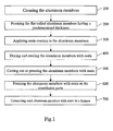
- Fig. 1 shows the steps of a method of manufacturing a heat exchanger according to the present invention.
- a heat exchanger of the present invention used in automotive air systems are explained, as follows.
- aluminum members which are coated with a resin, may be formed, e.g., die pressed, as constituent parts of a heat exchanger, e.g, a heat transfer member, a heater core, or the like.
- a thermoplastic resin or a thermosetting resin may be used for coating the aluminum members.
- a resin having lubricity is coated, e.g., applied or clad, to the aluminum members.
- the aluminum members further may be molded in a die press.
- the resin-coated aluminum members may be manufactured in the following manner.
- Aluminum members are cleaned (step 100). After they are cleaned, the aluminum members are formed, e.g, flat-rolled or the like, according to a predetermined thickness (step 200).
- a resin coating may be applied to at least one surface of the aluminum members (step 300).
- the aluminum members may be dried and cooled (step 400).
- the aluminum members then may be rolled into a coil-shape.
- the resin-coated aluminum members are cut out to a predetermined size for each of the constituting parts, e.g, a heat transfer member, a heater core, or the like, of the heat exchanger (step 500). Each member may be pressed, drilled, or drawn, as necessary (step 600).
- the aluminum members may be cut out to a predetermined size for each of the constituent parts of the heat exchanger after the resin-coated aluminum members are pressed, drilled, or drawn, or the like (not shown).
- the aluminum members of heat exchanger are formed as constituent parts, e.g., a heat transfer member, a heater core, or the like, of the heat exchanger.
- the aluminum members are placed in a furnace, in which they are fused together (step 700). In the furnace, the temperature is increased to a melting temperature or a softening temperature, as appropriate, of the coating resin or to a higher temperature.
- the aluminum members are thereby connected together by fusing the resin coating on each of the aluminum members to form the constituent parts, e.g., a heat transfer member, a heater core, or the like, of the heat exchanger. Because a resin is used to join the aluminum members, the temperature of the furnace is increased to, and maintained at, a melting point or a softening point, as appropriate, of the selected resin.
- the melting point or the softening point of a suitable resin generally falls within a range between about 90°C and about 300°C.
- the temperature of the furnace need not be increased to about 600°C, as is common for melting brazing filler metals used in known heat exchangers.
- energy consumption of the furnace may be reduced effectively by the use of resins.
- the manufacturing cost of the heat exchangers, according to the present invention also may be reduced due to the reduced energy consumption of the furnace.
- the aluminum members are formed as constituent parts of a heat exchanger that come into contact with water, e.g., a heater core, or the like, those aluminum members of the heat exchanger that are in contact with water may require some form of corrosion protection.
- cladding comprising an anti-corrosion material may be applied on those aluminum members that are in contact with water, or the thickness of the aluminum members may be increased to better withstand corrosion.
- adding an anti-corrosion material to the aluminum members may not be necessary. Therefore, corrosion resistance of the heat exchanger of the present invention may be achieved by using aluminum members coated with a resin that provides protection against corrosion.
- the manufacturing cost of the heat exchanger may be reduced.
- the thickness of the aluminum members need not be increased in order to improve their corrosion resistance. Accordingly, the amount of aluminum needed for the manufacture of the aluminum members may be reduced, and the manufacturing cost of the heat exchanger may be reduced further. Moreover, by providing aluminum members of reduced thickness, the weight of the heat exchanger may be reduced effectively.
- lubricating oil or another lubricant may be used to permit or enhance relative movement, and to reduce friction, between the aluminum members and the die press.
- the aluminum members may be cleaned, e.g., degreased.
- the resin-coated aluminum members have increased lubricity.
- a variety of resins may be used to coat the aluminum members that form constituent parts of the heat exchanger.
- Suitable resins used to the aluminum members of a heat exchanger include, e.g., a polyester resin, a nylon resin, a vinylidene fluoride resin, and similar thermoplastic and thermosetting resins.
- the softening point of a polyester resin may be in a range between about 165°C and about 185°C.
- the melting point of a nylon resin may be in a range between about 95°C and about 130°C.
- the melting point of vinylidene fluoride resin may be in a range between about 250°C and about 270°C. Therefore, the temperature of the furnace, which is used to join the aluminum members by fusing the resin, may be set in accordance with the softening point or melting point, as appropriate, of each of the resins that are used.
- a resin coating may be applied to a surface or surfaces of each aluminum member.
- the resin coating may be applied to a particular surface, or to particular surfaces, of an aluminum member depending upon the particular constituent part of a heat exchanger, into which the aluminum member is to be formed, e.g., a heat transfer member, a heater core, or the like.
- the thickness of the resin coating preferably is in a range between about 5 ⁇ m and about 50 ⁇ m .
- Resin spraying may be employed to provide a uniform thickness resin coating and to reduce the amount of resin that is used to the coat the aluminum members.
- the strength of the connections between the aluminum members coated with a resin may be increased compared with the connections formed by known brazing filler metals.
- the following examples are provided to demonstrate the strength of connections formed between resin-coated aluminum members.
- Flat, plate-shaped aluminum members having a width of about 30mm, were formed.
- the edge of two flat, plate shaped aluminum members were overlapped along a length of about 50mm and a width of about 30mm.
- the aluminum members were coated with a resin and then connected by fusing the resin coatings. After the aluminum members were connected, the strength of the connection between the members was measured by pulling both sides of the connected members apart using a tensile test machine.
- the resins used were a polyester resin (softening point: about 180° C), a nylon resin (melting point: in a range between about 95°C and about 130°C), and a vinylidene fluoride resin (melting point: about 260°C).
- the polyester resin was coated in one layer on each surface of one pair of flat, plate-shaped aluminum members to a thickness of about 5 ⁇ m .
- the nylon resin was coated in one layer on each surface of another pair of flat, plate-shaped aluminum members to a thickness of about 5 ⁇ m.
- An epoxy resin was sprayed for a first coat on a third pair of flat, plate-shaped aluminum members.
- the vinylidene fluoride resin was coated in two layers on each surface of the third pair of aluminum members to a thickness of about 20 ⁇ m.
- a respective resin i.e., two aluminum members coated with a polyester resin, two aluminum members coated with a nylon resin, two aluminum members coated with an epoxy and a vinylidene fluoride resin
- the aluminum members of each pair were overlapped, as described above.
- each of the two overlapped aluminum members was placed in a furnace under the conditions that appear in the following table to fuse the aluminum members together. After the fused aluminum members were cooled, a tensile test was performed on each of the respective, connected aluminum members.
- the heat exchanger formed by fusing aluminum members coated with a resin may achieve extensive reductions in manufacturing cost, a simplified manufacturing process, and a high strength of connection between the aluminum members.
- the present invention may be suitable for a stacked-type heat excchanger, which has a plurality of heat transfer tubes and a plurality of fins stacked alternately.
- the heat transfer tubes and fins may be stacked together and connected by fusing a resin coating on the heat transfer tubes and the fins at a lower temperature than is common using known methods with brazing filler metals.
- the present invention reduces the energy consumption in the furnace compared with known methods of making heat exchangers.
- the present invention may be suitable for a heat exchanger having a plurality of heat transfer tubes, each of which is formed by a pair of tube plates. The flange portions of each pair of tube plates are fused together.
- the pair of tube plates may be fused efficiently in the furnace at a lower temperature than is used in the known methods. Because the resin is coated uniformly on the aluminum members, the pair of tube plates is connected with uniformity along the length of the tube plates. As a result, seal efficiency of the fused tube plates may be increased. Moreover, because a high fusion strength is achieved between the aluminum members, as disclosed in the above-described examples, heat exchangers according to the present invention may operate at higher pressures than known heat exchangers that are made using known methods.
- the energy consumed during connection of the aluminum members of the heat exchanger may be effectively reduced, and the manufacturing cost of the heat exchanger may be reduced, as well.
- spraying flux upon the aluminum members which is common in known methods that use brazing filler metals, is not necessary. Therefore, the cost of the manufacturing time for spraying flux, in addition to the cost of flux, may be eliminated.
- the possibility of forming an incomplete or an insufficiently-strong brazing connection, which may accompany an uneven or an imprecise flux spray using known methods may be eliminated.
- the use of a lubricant on aluminum members, and a solvent to remove lubricant from each of the aluminum members is no longer necessary. Consequently, the manufacturing cost of the heat exchanger again may be reduced.
Landscapes
- Engineering & Computer Science (AREA)
- Physics & Mathematics (AREA)
- Thermal Sciences (AREA)
- Mechanical Engineering (AREA)
- General Engineering & Computer Science (AREA)
- Heat-Exchange Devices With Radiators And Conduit Assemblies (AREA)
- Application Of Or Painting With Fluid Materials (AREA)
Applications Claiming Priority (2)
| Application Number | Priority Date | Filing Date | Title |
|---|---|---|---|
| JP2001038539A JP2002243395A (ja) | 2001-02-15 | 2001-02-15 | 熱交換器およびその製造方法 |
| JP2001038539 | 2001-02-15 |
Publications (2)
| Publication Number | Publication Date |
|---|---|
| EP1233245A2 true EP1233245A2 (fr) | 2002-08-21 |
| EP1233245A3 EP1233245A3 (fr) | 2003-07-02 |
Family
ID=18901493
Family Applications (1)
| Application Number | Title | Priority Date | Filing Date |
|---|---|---|---|
| EP02250554A Withdrawn EP1233245A3 (fr) | 2001-02-15 | 2002-01-28 | Echangeurs de chaleur et méthodes de production de ces échangeurs |
Country Status (3)
| Country | Link |
|---|---|
| US (1) | US6945321B2 (fr) |
| EP (1) | EP1233245A3 (fr) |
| JP (1) | JP2002243395A (fr) |
Cited By (3)
| Publication number | Priority date | Publication date | Assignee | Title |
|---|---|---|---|---|
| EP1808264A1 (fr) | 2006-01-11 | 2007-07-18 | Akzo Nobel Coatings International B.V. | Composition de flux de soudure comportant un lubrifiant |
| WO2014147035A1 (fr) * | 2013-03-18 | 2014-09-25 | Behr Gmbh & Co. Kg | Procédé pour produire des éléments échangeurs de chaleur couplés |
| DE102014217075A1 (de) * | 2014-08-27 | 2016-03-03 | Mahle International Gmbh | Verfahren zum Herstellen einer Temperiervorrichtung und Temperiervorrichtung |
Families Citing this family (9)
| Publication number | Priority date | Publication date | Assignee | Title |
|---|---|---|---|---|
| NL1022794C2 (nl) * | 2002-10-31 | 2004-09-06 | Oxycell Holding Bv | Werkwijze voor het vervaardigen van een warmtewisselaar, alsmede met de werkwijze verkregen warmtewisselaar. |
| JP4418182B2 (ja) * | 2003-06-25 | 2010-02-17 | ソマール株式会社 | 熱交換器形成用材料、これを用いた熱交換器の製造方法及び熱交換器 |
| US7669327B2 (en) * | 2004-09-01 | 2010-03-02 | Jw Aluminum Company | Methods of applying ozone-depleting catalysts to heat exchangers |
| US20070187462A1 (en) * | 2006-01-11 | 2007-08-16 | Aleris Aluminum Koblenz Gmbh | Method of manufacturing a brazed assembly |
| WO2014112600A1 (fr) * | 2013-01-18 | 2014-07-24 | 大成プラス株式会社 | Échangeur thermique et procédé pour sa fabrication |
| EP2808114A3 (fr) * | 2013-05-30 | 2015-09-02 | Lucas-Milhaupt, Inc. | Procédé de revêtement de flux des préformes de brasure et parties discrètes |
| JP7126388B2 (ja) | 2018-06-28 | 2022-08-26 | 昭和電工パッケージング株式会社 | 樹脂融着製熱交換器 |
| JP7239370B2 (ja) * | 2019-03-28 | 2023-03-14 | 株式会社レゾナック・パッケージング | 熱交換器 |
| JP7781514B2 (ja) * | 2019-12-25 | 2025-12-08 | 株式会社Dnp高機能マテリアル彦根 | 熱交換器およびそのインナーフィン |
Family Cites Families (39)
| Publication number | Priority date | Publication date | Assignee | Title |
|---|---|---|---|---|
| US2569097A (en) | 1951-02-20 | 1951-09-25 | Gen Motors Corp | Method of coating ferrous metal with aluminum or an aluminum alloy |
| US3310868A (en) | 1964-05-04 | 1967-03-28 | Fedders Corp | Method of making radiators |
| US3440712A (en) | 1966-10-27 | 1969-04-29 | Aluminum Co Of America | Brazing aluminum |
| US3498371A (en) * | 1967-06-12 | 1970-03-03 | Alfred E Zygiel | Heat transfer device |
| US3489448A (en) | 1967-08-17 | 1970-01-13 | Nippon Denso Co | Method of making aluminum heat exchangers |
| DE1601216B2 (de) * | 1967-11-03 | 1971-06-16 | Linde Ag, 6200 Wiesbaden | Blechtafel fuer platten waermetauscher mit einem stapel solcher blechtafeln |
| US3666006A (en) * | 1970-05-04 | 1972-05-30 | Olin Corp | Heat exchanger |
| IT969325B (it) | 1971-08-06 | 1974-03-30 | Chausson Usines Sa | Procedimento per la brasatura di radiatori in alluminio e radiato ri ottenuti |
| FR2199489B1 (fr) | 1972-09-21 | 1975-06-13 | Chausson Usines Sa | |
| JPS5461015A (en) | 1977-10-25 | 1979-05-17 | Kobe Steel Ltd | Manufacture of aluminum-soldered fin heat exchanger |
| JPS57184892A (en) * | 1981-05-06 | 1982-11-13 | Sharp Corp | Sensible heat exchanger |
| JPS582596A (ja) | 1981-06-30 | 1983-01-08 | Nippon Parkerizing Co Ltd | アルミニウム製熱交換器の表面処理法 |
| FR2512715A1 (fr) | 1981-09-17 | 1983-03-18 | Chausson Usines Sa | Procede pour le brasage d'echangeurs de chaleur par soufflage de gaz chauds et four pour sa mise en oeuvre |
| US4428418A (en) * | 1982-05-17 | 1984-01-31 | Chromalloy American Corporation | Heat exchanger fin element with folded over side edges |
| US4601089A (en) * | 1983-10-21 | 1986-07-22 | Pal Gal | Process for the manufacture of heat-exchanger elements of strip-finned heat-exchangers |
| US4732311A (en) | 1984-05-31 | 1988-03-22 | Nippondenso Co., Ltd. | Process of producing lightweight and corrosion-resistant heat exchanger |
| US4571352A (en) | 1985-01-16 | 1986-02-18 | Sanden Corporation | Method for coating aluminum metal body with aluminum alloy brazing filler metal |
| JPS61184395A (ja) | 1985-02-12 | 1986-08-18 | Sanden Corp | アルミニウム製熱交換器の防食処理法 |
| JPH0612217B2 (ja) * | 1985-04-30 | 1994-02-16 | 日本電装株式会社 | アルミニウム製熱交換器およびその製法 |
| JPS62140677A (ja) | 1985-12-13 | 1987-06-24 | Taiheiyo Kiko Kk | 粉粒体の塗布方法 |
| JPS6357674A (ja) * | 1986-08-28 | 1988-03-12 | Nippon Paint Co Ltd | 親水性皮膜形成用処理剤及び処理方法 |
| JPS63117085A (ja) * | 1986-11-05 | 1988-05-21 | Central Glass Co Ltd | 粘着剤用樹脂組成物 |
| AU597475B2 (en) | 1987-02-27 | 1990-05-31 | Nihon Radiator Co., Ltd. | Heat exchanger core made of aluminum and method for application of flux during process of soldering thereof |
| US4781320A (en) | 1987-04-27 | 1988-11-01 | Nihon Radiator Co., Ltd. | Method for the production of a heat exchanger |
| JPH01157794A (ja) | 1987-09-09 | 1989-06-21 | Nippon Denso Co Ltd | ろう付用アルミニウム素材,その製法及びアルミニウム合金製熱交換器の製法 |
| US4989775A (en) | 1987-12-15 | 1991-02-05 | Showa Aluminum Kabushiki Kaisha | Method for brazing aluminum components |
| US5800673A (en) * | 1989-08-30 | 1998-09-01 | Showa Aluminum Corporation | Stack type evaporator |
| JP2798093B2 (ja) | 1990-03-02 | 1998-09-17 | 日本ペイント株式会社 | 潤滑性親水化処理剤及び処理方法 |
| JP2825949B2 (ja) | 1990-07-26 | 1998-11-18 | サンデン株式会社 | ろう付け方法 |
| JP2689358B2 (ja) * | 1991-02-18 | 1997-12-10 | 株式会社ゼクセル | 熱交換器 |
| JP3302713B2 (ja) * | 1992-02-05 | 2002-07-15 | 大洋製鋼株式会社 | 傷部耐食性・加工性を兼ね備えた高耐久性塗装金属板及びその連続製造方法 |
| EP0623653B1 (fr) * | 1993-05-07 | 2000-12-06 | Nippon Paint Co., Ltd. | Solutions aqueuses de polyoxyalkylène pour le traitement de surface |
| JPH07251130A (ja) | 1994-03-11 | 1995-10-03 | Kansai Paint Co Ltd | 撥水性塗膜形成方法 |
| US5538078A (en) | 1994-04-08 | 1996-07-23 | Nippondenso Co., Ltd. | Aluminum-containing metal composite material and process for producing same |
| WO1996019298A1 (fr) | 1994-12-22 | 1996-06-27 | Henkel Corporation | Procede pour recouvrir d'un revetement protecteur l'aluminium et ses alliages ainsi que des articles composites contenant de l'aluminium et des alliages d'aluminium |
| JPH11131254A (ja) | 1997-10-24 | 1999-05-18 | Nippon Parkerizing Co Ltd | アルミニウム含有金属材料の表面処理方法 |
| JP3337416B2 (ja) | 1998-02-24 | 2002-10-21 | 株式会社デンソー | ろう付け性に優れた自動車熱交換器用アルミニウム押出多孔偏平管およびその製造方法 |
| TW415867B (en) | 1998-07-29 | 2000-12-21 | Calsonic Corp | Method for applying flux for use in brazing aluminum material, flux coating apparatus, and method for manufacturing a heat exchanger |
| JP2001167782A (ja) | 1999-09-28 | 2001-06-22 | Calsonic Kansei Corp | 燃料電池用循環水熱交換器の製造方法 |
-
2001
- 2001-02-15 JP JP2001038539A patent/JP2002243395A/ja active Pending
-
2002
- 2002-01-24 US US10/053,582 patent/US6945321B2/en not_active Expired - Fee Related
- 2002-01-28 EP EP02250554A patent/EP1233245A3/fr not_active Withdrawn
Cited By (3)
| Publication number | Priority date | Publication date | Assignee | Title |
|---|---|---|---|---|
| EP1808264A1 (fr) | 2006-01-11 | 2007-07-18 | Akzo Nobel Coatings International B.V. | Composition de flux de soudure comportant un lubrifiant |
| WO2014147035A1 (fr) * | 2013-03-18 | 2014-09-25 | Behr Gmbh & Co. Kg | Procédé pour produire des éléments échangeurs de chaleur couplés |
| DE102014217075A1 (de) * | 2014-08-27 | 2016-03-03 | Mahle International Gmbh | Verfahren zum Herstellen einer Temperiervorrichtung und Temperiervorrichtung |
Also Published As
| Publication number | Publication date |
|---|---|
| US20020139519A1 (en) | 2002-10-03 |
| US6945321B2 (en) | 2005-09-20 |
| EP1233245A3 (fr) | 2003-07-02 |
| JP2002243395A (ja) | 2002-08-28 |
Similar Documents
| Publication | Publication Date | Title |
|---|---|---|
| EP1233245A2 (fr) | Echangeurs de chaleur et méthodes de production de ces échangeurs | |
| CA1088974A (fr) | Collage de bobines en aluminium | |
| JP7281866B2 (ja) | フィンアンドチューブ型熱交換器及びその製造方法 | |
| US6120848A (en) | Method of making a braze sheet | |
| CA2275569A1 (fr) | Faisceau d'echangeur thermique a base d'aluminium et son procede de production | |
| JP2012052747A (ja) | フィン・アンド・チューブ型熱交換器用伝熱管及びそれを用いたフィン・アンド・チューブ型熱交換器並びにその製造方法 | |
| EP4164836B1 (fr) | Matériau de feuille de brasage d'alliage d'aluminium multicouches pour brasage exempt de flux | |
| US6604669B1 (en) | Manifold for heat exchanger and process therefor | |
| KR20050084231A (ko) | 알루미늄 합금 브레이징 재료, 브레이징용 부재, 상기재료를 사용한 브레이징 물품 및 그 제조 방법, 브레이징용열교환 튜브, 및 상기 브레이징용 열교환 튜브를 사용한열교환기 및 그 제조 방법 | |
| JPH1133709A (ja) | アルミニウム合金製チューブ及び熱交換器 | |
| US6422451B2 (en) | Interconnection of aluminum components | |
| US7213737B2 (en) | Graphite braze bar inserts | |
| CA3162701C (fr) | Materiau du type tole a brasage en alliage d'aluminium multicouche pour brasage sans flux | |
| JPS6334495A (ja) | アルミニウム熱交換器 | |
| US20060196645A1 (en) | Heat exchanger with multilayer cladded tubes | |
| JPH0612219B2 (ja) | 熱交換器の製造方法 | |
| CA3181199C (fr) | Materiau de tole a brasage en alliage d'aluminium multicouche pour brasage sans flux | |
| KR100707479B1 (ko) | 알루미늄 클래드판과 그 제조방법 | |
| KR20020076910A (ko) | 알루미늄 제품의 접합재와 그 코팅방법 및 장치 | |
| JP2009082971A (ja) | 耐食性が良好なアルミニウム合金製熱交換器の継手及びそれを用いた熱交換器、並びにそれらの製造方法 | |
| JPH0612218B2 (ja) | 熱交換器の製造方法 | |
| JP2001276966A (ja) | 熱交換器用伝熱管及びフィンチューブ型熱交換器 | |
| KR100364378B1 (ko) | 열 교환기의 제조방법 | |
| KR20030039194A (ko) | 열교환기의 헤더파이프 접합방법과 그 접합재 | |
| EP2902146A1 (fr) | Procédure et appareil d'assemblage de composants métalliques résistants de recuit |
Legal Events
| Date | Code | Title | Description |
|---|---|---|---|
| PUAI | Public reference made under article 153(3) epc to a published international application that has entered the european phase |
Free format text: ORIGINAL CODE: 0009012 |
|
| 17P | Request for examination filed |
Effective date: 20020215 |
|
| AK | Designated contracting states |
Kind code of ref document: A2 Designated state(s): AT BE CH CY DE DK ES FI FR GB GR IE IT LI LU MC NL PT SE TR |
|
| AX | Request for extension of the european patent |
Free format text: AL;LT;LV;MK;RO;SI |
|
| PUAL | Search report despatched |
Free format text: ORIGINAL CODE: 0009013 |
|
| RIC1 | Information provided on ipc code assigned before grant |
Ipc: 7B 23K 35/36 B Ipc: 7F 28F 13/18 B Ipc: 7F 28F 13/04 B Ipc: 7B 23K 1/20 B Ipc: 7F 28F 19/04 A |
|
| AK | Designated contracting states |
Designated state(s): AT BE CH CY DE DK ES FI FR GB GR IE IT LI LU MC NL PT SE TR |
|
| AX | Request for extension of the european patent |
Extension state: AL LT LV MK RO SI |
|
| AKX | Designation fees paid |
Designated state(s): DE FR |
|
| 17Q | First examination report despatched |
Effective date: 20081219 |
|
| STAA | Information on the status of an ep patent application or granted ep patent |
Free format text: STATUS: THE APPLICATION IS DEEMED TO BE WITHDRAWN |
|
| 18D | Application deemed to be withdrawn |
Effective date: 20090430 |