EP1233531A1 - Systeme de communication d'information, carte a circuit imprime sans contact et puce associee - Google Patents
Systeme de communication d'information, carte a circuit imprime sans contact et puce associee Download PDFInfo
- Publication number
- EP1233531A1 EP1233531A1 EP00971742A EP00971742A EP1233531A1 EP 1233531 A1 EP1233531 A1 EP 1233531A1 EP 00971742 A EP00971742 A EP 00971742A EP 00971742 A EP00971742 A EP 00971742A EP 1233531 A1 EP1233531 A1 EP 1233531A1
- Authority
- EP
- European Patent Office
- Prior art keywords
- response signal
- time
- time slot
- transmission
- signal
- Prior art date
- Legal status (The legal status is an assumption and is not a legal conclusion. Google has not performed a legal analysis and makes no representation as to the accuracy of the status listed.)
- Withdrawn
Links
Images


Classifications
-
- G—PHYSICS
- G06—COMPUTING OR CALCULATING; COUNTING
- G06K—GRAPHICAL DATA READING; PRESENTATION OF DATA; RECORD CARRIERS; HANDLING RECORD CARRIERS
- G06K7/00—Methods or arrangements for sensing record carriers, e.g. for reading patterns
- G06K7/10—Methods or arrangements for sensing record carriers, e.g. for reading patterns by electromagnetic radiation, e.g. optical sensing; by corpuscular radiation
- G06K7/10009—Methods or arrangements for sensing record carriers, e.g. for reading patterns by electromagnetic radiation, e.g. optical sensing; by corpuscular radiation sensing by radiation using wavelengths larger than 0.1 mm, e.g. radio-waves or microwaves
- G06K7/10019—Methods or arrangements for sensing record carriers, e.g. for reading patterns by electromagnetic radiation, e.g. optical sensing; by corpuscular radiation sensing by radiation using wavelengths larger than 0.1 mm, e.g. radio-waves or microwaves resolving collision on the communication channels between simultaneously or concurrently interrogated record carriers.
- G06K7/10029—Methods or arrangements for sensing record carriers, e.g. for reading patterns by electromagnetic radiation, e.g. optical sensing; by corpuscular radiation sensing by radiation using wavelengths larger than 0.1 mm, e.g. radio-waves or microwaves resolving collision on the communication channels between simultaneously or concurrently interrogated record carriers. the collision being resolved in the time domain, e.g. using binary tree search or RFID responses allocated to a random time slot
- G06K7/10059—Methods or arrangements for sensing record carriers, e.g. for reading patterns by electromagnetic radiation, e.g. optical sensing; by corpuscular radiation sensing by radiation using wavelengths larger than 0.1 mm, e.g. radio-waves or microwaves resolving collision on the communication channels between simultaneously or concurrently interrogated record carriers. the collision being resolved in the time domain, e.g. using binary tree search or RFID responses allocated to a random time slot transponder driven
-
- G—PHYSICS
- G06—COMPUTING OR CALCULATING; COUNTING
- G06K—GRAPHICAL DATA READING; PRESENTATION OF DATA; RECORD CARRIERS; HANDLING RECORD CARRIERS
- G06K19/00—Record carriers for use with machines and with at least a part designed to carry digital markings
- G06K19/06—Record carriers for use with machines and with at least a part designed to carry digital markings characterised by the kind of the digital marking, e.g. shape, nature, code
- G06K19/067—Record carriers with conductive marks, printed circuits or semiconductor circuit elements, e.g. credit or identity cards also with resonating or responding marks without active components
- G06K19/07—Record carriers with conductive marks, printed circuits or semiconductor circuit elements, e.g. credit or identity cards also with resonating or responding marks without active components with integrated circuit chips
- G06K19/0723—Record carriers with conductive marks, printed circuits or semiconductor circuit elements, e.g. credit or identity cards also with resonating or responding marks without active components with integrated circuit chips the record carrier comprising an arrangement for non-contact communication, e.g. wireless communication circuits on transponder cards, non-contact smart cards or RFIDs
-
- G—PHYSICS
- G06—COMPUTING OR CALCULATING; COUNTING
- G06K—GRAPHICAL DATA READING; PRESENTATION OF DATA; RECORD CARRIERS; HANDLING RECORD CARRIERS
- G06K7/00—Methods or arrangements for sensing record carriers, e.g. for reading patterns
- G06K7/0008—General problems related to the reading of electronic memory record carriers, independent of its reading method, e.g. power transfer
Definitions
- the present invention relates to an information communication system for conducting communications between a master station and a plurality of slave stations, a contactless IC card used as a slave station in the information communication system, and an IC chip.
- a user carries a plurality of commuter tickets (slave stations), they respond to a request from the master station by transmitting a plurality of response signals simultaneously.
- the system has a problem that the master station cannot appropriately recognize overlapping response signals from the slave stations. This problem is especially serious when the master station attempts, at the start of the communication, to acquire the identifiers (hereafter abbreviated as "IDs") of the slave stations. Once having acquired the IDs of the slave stations, the master station can separately transmit or receive information to/from the slave stations by adding the IDs to signals.
- IDs identifiers
- time slots As one method for avoiding the overlapping of response signals from slave stations, use of time slots is currently studied. In this method, a time period during which the slave stations are allowed to transmit their response signals is divided into a plurality of time slots having a certain time length. Each slave station then selects one time slot at random and transmits a response signal during the selected time slot.
- FIG. 1 is a timing chart for explaining a case where a master station 901 conducts information communications with each of a plurality of slave stations (in this example, a slave station A 902, a slave station B 903, a slave station C 904, and a slave station D 905).
- a master station 901 conducts information communications with each of a plurality of slave stations (in this example, a slave station A 902, a slave station B 903, a slave station C 904, and a slave station D 905).
- each slave station When receiving the first ID request signal 911 transmitted from the master station 901, each slave station transmits an ID response signal with timing corresponding to a time slot number which is determined by the slave station at random.
- the slave station A 902 selects a time slot with the slot number 1 and transmits an ID response signal 912 with timing corresponding to the selected time slot number 1.
- the remaining slave stations B 903 to D 905 select a time slot with the slot number 2 and transmit their ID response signals with timing corresponding to the selected time slot number 2.
- the slave station 901 can recognize the ID response signal 912 transmitted from the slave station A 902, because only the ID response signal 912 is transmitted during the time slot 1 without overlapping.
- the master station 901 cannot recognize any of the ID response signals 913, 914, and 915 that are transmitted during the time slot 2 since they overlap with one another.
- the master station 901 needs to transmit an ID request signal 916 for the second time to each of the slave stations B 903 to D 905 to acquire the IDs.
- each slave station Upon receiving the second ID request signal 916, each slave station transmits the ID response signal for the second time with timing corresponding to the time slot number selected at random.
- the second ID request signal 916 is attached with information indicating that the slave station A 902 need not transmit the ID response signal to the second ID request signal 916, because the master station has already acquired the ID of the slave station A 902. In this way, by retransmitting the ID request signal, the master station 901 can finally acquire the IDs of all the slave stations.
- the number of time slots may be increased. For example, if ten time slots instead of four shown in FIG. 1 are provided, a probability that a plurality of slave stations select the same time slot will be decreased.
- both methods i.e., the method of allowing the master station 901 to repeat transmitting the ID request signal and the method of increasing the time slot numbers
- both methods have a problem that the whole processing time tends to be increased.
- all processes including a process for writing data into each slave station have to be completed in a predetermined time period during which the slave stations are in an area in which they can communicate with the master station (hereinafter, this area is referred to as "service area") .
- service area this area in which the slave stations are in an area in which they can communicate with the master station
- increase in the processing time may cause a problem that the whole process does not complete in the predetermined time period. This is a serious problem from a practical point of view.
- An information communication system including a master station and a plurality of slave stations which perform contactless communication with the master station, wherein each slave station comprises: reception means for receiving a signal from the master station; transmission means for transmitting a response signal in response to the signal from the master station; time slot determining means for determining a time slot used to transmit the response signal; and time delay determining means for determining a delayed time for transmitting the response signal within the determined time slot.
- This construction increases the possibility that transmission starting timing of response signals are different from one slave station to another, even when the plurality of slave stations select the same time slot. With this, the possibility that, by a certain operation done by the master station or each slave station, the master station can normally recognize at least one response signal form a slave station increases. This also reduces the whole processing time.
- each slave station may further comprises: detecting means for detecting a transmission of a response signal by another slave station having been performed prior to the determined delayed time within the same time slot; and response signal transmission control means for controlling not to transmit the response signal if the detecting means detects the transmission of the response signal.
- each slave station can be controlled so as not to transmit its response signal, whereby such overlap can be avoided.
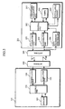
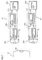
- FIG. 2 is a schematic block diagram showing the construction of the master station 101 (reader/writer) and the slave station 201 (contactless IC card) in the information communication system of the present invention.
- the master station 101 includes a control unit 102, a modulation unit 103, a demodulation unit 104, a memory 105, and an antenna 106.
- the slave station 201 includes a control unit 202, a modulation unit 203, a demodulation unit 204, a nonvolatile memory 205, a timer 206, a time number generation unit 207, a data transmission detection unit 208, and an antenna 209.
- the master station 101 allows the memory 105 and the control unit 102 to generate a request signal, allows the modulation unit 103 to modulate the generated request signal by the Amplitude Shift Keying (ASK) modulation or the like, and transmits the modulated request signal to the slave station 201 via the antenna 106.
- ASK Amplitude Shift Keying
- the contactless IC card as the slave station 201 in this embodiment does not contain a battery, and uses as the power source the electromotive force that is generated across the antenna 209 when the antenna receives a radio wave from the master station.
- the present invention can be applied to contactless IC cards complying with the ISO14 or IS015693 standard, but is not limited to them.
- the demodulation unit 104 demodulates the modulated wave received from the slave station via the antenna 106 and passes the demodulated signal to the control unit 102.
- the control unit 102 performs necessary processes based on the information transmitted from the slave station 201.
- the demodulation unit 204 in the slave station demodulates the modulated wave received from the master station 101 via the antenna 209 and passes the demodulated signal to the control unit 202.
- the control unit 202 includes a logic circuit as a main component. This control unit 202 performs various processes including a process for writing/reading data on/from the nonvolatile memory 205, based on commands and data transmitted from the master station 101, and generates a response signal to the master station 101.
- the generated response signal is modulated by the modulation unit 203 by the BPSK modulation method or the like and transmitted to the master station 101 via the antenna 209.
- the time number generation unit 207 allows the control unit 202 to generate time slot numbers and time delay numbers which are used in transmitting the ID of the slave station 201 in response to the ID request signal from the master station 101.
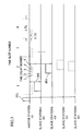
- FIG. 3 is a timing chart for explaining the time delays.
- this embodiment provides time delays in each time slot.
- the timing with which the ID response signal is transmitted from the slave station 201 to the master station 101 is delayed based on the time delay number determined by the time number generation unit 207 of the slave station 201.
- the delayed times are obtained by repetitively delaying the ID response signal transmission start timing of the slave station 201 by a certain time period.
- the delayed times are assigned with numbers called time delay numbers.
- the time number generation unit 207 in the slave station B 401 generates a number "2" for both the time slot number and time delay number. Then, after receiving the ID request signal 191 from the master station 101, the slave station B 401 waits until the time slot 2, further waits and transmits the ID response signal 491 with the timing of the time delay 2.
- the slave station C 501 generates "2" and "4" for the time slot number and time delay number, respectively, and the slave station D 601 generates "2" and "3", respectively.
- FIG. 3 shows that the slave stations C 501 and D 601 do not transmit response signals in the time slot 2 since the slave station B 401 has already transmitted the ID response signal at the time delay 2 in the time slot 2.
- the present embodiment at least prevents the case where the master station cannot acquire an ID from any of a plurality of slave stations using the same time slot, by allowing the plurality of slave stations using the same time slot to transmit ID response signals with different timing and exercising a control so that when one of the plurality of slave stations detects that another one of them has already transmitted an ID response signal, the slave station refrains from transmitting an ID response signal.
- the slave stations C 501 and D 601 do not transmit the ID response signals since the data transmission detection units 208 of the slave stations C 501 and D 601 detect transmission of the ID response signal by the slave station B 401.
- time duration ⁇ Td between each delayed time is set to such a time duration as is enough for the data transmission detection unit 208 to detect that another slave station has transmitted an ID response signal.
- the time duration ⁇ Td is represented by the following formula: ⁇ Ts > (packet transmission time period) + ⁇ Td ⁇ N, where ⁇ Ts represents a time period of one time slot, and N the number of delayed times.
- the master station 101 receives, as a response to the first ID request signal 191, the ID response signal 391 from the slave station A 301 and the ID response signal 491 from the slave station B 401 and acquires IDs of these slave stations.
- the slave station B 401 no longer needs to transmit an ID response signal in response to the second ID request signal 192 (See FIG. 4).
- a probability of occurrence of the overlapping of response signals from slave stations is reduced. This leads to the reduction in the number of times the master station 101 transmits the ID request signal to the slave stations. This also contributes to the reduction in the processing time of the whole system.
- the slave stations having transmitted an ID response signal in response to the first ID request signal do not transmit the ID response signal in response to the second ID request signal. Accordingly, no slave station transmits an ID response signal in response to the third ID request signal that is not illustrated in FIG. 4. This allows the master station 101 to detect that all IDs of the slave stations currently in the service area have been acquired. This enables the master station to separately transmit or receive information to/from the slave stations by adding the IDs to signals.
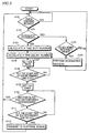
- FIG. 5 is a flow chart showing the procedures by the control unit 202 of the slave station 201.
- the slave station 201 When the slave station 201 enters the service area, the slave station 201 powers up under the influence of electric waves from the master station 101, and the procedure shown in FIG. 5 starts.
- the control unit 202 in the slave station 201 awaits a command from the master station 101 (S101).
- the control unit 202 judges whether the command is an ID request command or not (S102).
- the control unit 202 judges whether the ID expected to be attached to the command agrees with an ID held by the slave station 201 (S103). If they do not agree with each other (S103:No), it is judged that the received command is intended for another slave station, then the control returns to the command wait state without performing any process.
- control unit 202 performs the process designated by the command (S104).
- S104 The procedure explained so far enables the master station to separately handle processes requested by a plurality of slave stations in the service area.
- the time number generation unit 207 If the received command is an ID request command (S102:Yes), the time number generation unit 207 generates a time slot number (S105) and a time delay number (S106).
- time slot numbers and time delay numbers (hereafter, in generalization, they are referred to as time numbers) are generated will be described.
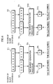
- FIG. 6 shows the method for generating the time numbers.
- each slave station generates the time numbers using the ID of each slave station.
- the main reason for this is that the use of the ID, which is uniquely assigned, is considered to be the preferable way to prevent a plurality of slave stations from generating the same time number so as to prevent the occurrence of overlapping response signals from the slave stations.
- IDs T1 "00230167” and T7 "00230168” are assigned to the slave stations A 301 and B 401, respectively.
- time slot numbers are generated using upper four digits, that is "0023" (T2 and T8) of the IDs T1 and T7, for both slave station A 301 and B 401.
- time delay numbers are generated using lower four digits of IDs, that is "0167” (T3) for the slave station A 301 and "0168” (T9) for the slave station B 401.
- time slot numbers (T5 and T11) and time delay numbers (T6 and T12) are generated, respectively.
- the same time slot number "2" (T5 and T11) is generated since the upper four digits of the two IDs are both "0023", but the probability that the same time delay number is generated is very low since the two IDs have different sets of lower four digits.
- different time delay numbers are generated ("2" for slave station A 301, represented as T6, and "4" for slave station B 401, represented as T12). Accordingly, the probability that the same time slot number and the same time delay number are generated is very low. As a result, even if the same time slot number is generated, it is highly possible that different time delay numbers are generated. This prevents the occurrence of overlapping ID response signals transmitted from a plurality of slave stations.
- the method for generating time numbers is not limited to the above-described one including the use of slave station IDs.
- a variety of methods can be applicable.
- a plurality of slave stations generate the same time number in response to the first ID request signal. So, it is preferable that each slave station generates, in response to the second ID request signal and onwards, a time number different from the previously generated one.
- the following methods are applicable: (a) a method of using a random number generation circuit provided in the time number generation unit 207; and (b) a combination of a method of generating a time number by assigning a different weight to each bit and a method of shifting bits of an input ID.
- the transmission timing of the ID response signal is controlled based on the generated time numbers.
- the value corresponding to the generated time slot number is set in the timer 206 (S107), and the control unit 202 waits until the time reaches the start time of the determined time slot (S108).
- the control unit 202 When the time reaches the start time of the determined time slot (S108: Yes), the value corresponding to the generated time delay number is set in the timer 206 (S109). Then, if the data transmission detection unit 208 detects that another slave station has transmitted an ID response signal (S110:Yes), the control unit 202 returns to the command wait state without performing a process.
- the control unit 202 transmits an ID response signal containing the ID of the slave station 201 (S112).
- the control returns to the command wait state.
- FIG. 7 shows the detailed construction of the data transmission detection unit 208. This figure also shows portions of the master station 101 including the antenna 106, and the slave stations A 301 and B 401.
- the slave station A 301 transmits a signal to the master station 101 by inputting a modulated response signal into a transistor (not illustrated) provided in the modulation unit 203a whose source and drain are respectively connected to the ends of the antenna 209a, allowing a load fluctuation to be generated.
- the slave station B 401 transmits a signal by inputting a modulated response signal into a transistor provided in the modulation unit 203b.
- the slave station B 401 detects a signal fluctuation that is input to the level comparator 210b via a signal line. Then, the level comparator 210b judges whether the detected signal fluctuation is a small signal fluctuation due to noise or the like, or a relatively large fluctuation due to transmission of the ID response signal by another slave station. The detection result is transmitted to the control unit 202b as a data transmission detection signal 211b.
- the level comparator 210b in the slave station B 401 judges that the detected fluctuation is a relatively large fluctuation due to transmission of the response signal by another slave station.
- the detection result transmitted to the control unit 202b prevents the slave station B 401 from transmitting a response signal to the master station.
- the control unit 202 can recognize that it does not indicate a response signal transmission by another slave station since the control unit 202 knows the slave station A 301 is transmitting a response signal. In this way, when a slave station transmits a response signal, the other slave stations can detect it and do not transmit a response signal.
- the present invention is applicable to information communication systems having a plurality of slave stations which are, for example, contactless IC cards.
Landscapes
- Engineering & Computer Science (AREA)
- Physics & Mathematics (AREA)
- Theoretical Computer Science (AREA)
- General Physics & Mathematics (AREA)
- Computer Vision & Pattern Recognition (AREA)
- Artificial Intelligence (AREA)
- Toxicology (AREA)
- Health & Medical Sciences (AREA)
- Computer Networks & Wireless Communication (AREA)
- Electromagnetism (AREA)
- General Health & Medical Sciences (AREA)
- Computer Hardware Design (AREA)
- Microelectronics & Electronic Packaging (AREA)
- Mobile Radio Communication Systems (AREA)
- Time-Division Multiplex Systems (AREA)
- Telephone Function (AREA)
- Near-Field Transmission Systems (AREA)
Applications Claiming Priority (3)
| Application Number | Priority Date | Filing Date | Title |
|---|---|---|---|
| JP31342299A JP2001136100A (ja) | 1999-11-04 | 1999-11-04 | 情報通信処理方式 |
| JP31342299 | 1999-11-04 | ||
| PCT/JP2000/007721 WO2001033725A1 (fr) | 1999-11-04 | 2000-11-02 | Systeme de communication d'information, carte a circuit imprime sans contact et puce associee |
Publications (2)
| Publication Number | Publication Date |
|---|---|
| EP1233531A1 true EP1233531A1 (fr) | 2002-08-21 |
| EP1233531A4 EP1233531A4 (fr) | 2004-11-03 |
Family
ID=18041117
Family Applications (1)
| Application Number | Title | Priority Date | Filing Date |
|---|---|---|---|
| EP00971742A Withdrawn EP1233531A4 (fr) | 1999-11-04 | 2000-11-02 | Systeme de communication d'information, carte a circuit imprime sans contact et puce associee |
Country Status (5)
| Country | Link |
|---|---|
| US (1) | US7187692B1 (fr) |
| EP (1) | EP1233531A4 (fr) |
| JP (1) | JP2001136100A (fr) |
| CN (1) | CN1175588C (fr) |
| WO (1) | WO2001033725A1 (fr) |
Cited By (8)
| Publication number | Priority date | Publication date | Assignee | Title |
|---|---|---|---|---|
| EP1313057A3 (fr) * | 2001-11-20 | 2004-02-04 | Matsushita Electric Industrial Co., Ltd. | Carte à puce sans contact, procède à réponse et programme correspondant |
| WO2004025544A1 (fr) * | 2002-09-11 | 2004-03-25 | Koninklijke Philips Electronics N.V. | Procede de lecture d'une pluralite de supports de donnees sans contact, comprenant un systeme anti-collision |
| EP1422652B1 (fr) * | 2002-11-20 | 2007-07-18 | Siemens Aktiengesellschaft | Procédé pour la transmission sans collision d'informations entre un appareil de lecture/écriture et un support d'information mobile, appareil de lecture/écriture et système d'identification |
| EP1889089A4 (fr) * | 2005-06-03 | 2009-01-07 | Tagent Corp | Fabrication d'etiquettes d'identification a haute frequence |
| WO2008141232A3 (fr) * | 2007-05-09 | 2009-02-19 | Atmel Corp | Gestion de puissance et de synchronisation dans un dispositif de carte à puce |
| EP2226742A1 (fr) * | 2002-12-17 | 2010-09-08 | Sony Corporation | Appareil et procédé de communication pour la détermination d'identificateurs de communication |
| US7958291B2 (en) | 2006-10-10 | 2011-06-07 | Atmel Rousset S.A.S. | Supplemental communication interface |
| EP2537120A4 (fr) * | 2010-02-18 | 2014-07-23 | Nokia Corp | Procédé et appareil de différenciation d'étiquettes rfid |
Families Citing this family (9)
| Publication number | Priority date | Publication date | Assignee | Title |
|---|---|---|---|---|
| DE10227558A1 (de) * | 2002-06-20 | 2004-01-15 | Infineon Technologies Ag | System zum Datenaustausch zwischen mindestens zwei kontaktlosen Datenträgern |
| WO2004100453A1 (fr) | 2003-05-07 | 2004-11-18 | Sony Corporation | Systeme de communication radio, dispositif de communication radio, procede de communication radio et programme informatique |
| DE602004017904D1 (de) * | 2003-12-23 | 2009-01-02 | Nxp Bv | Verfahren und schaltung zum erzeugen von stromversorgungs-unterbrechungszeit-informationen in einem kontaktlosen datenträger |
| JP4072503B2 (ja) * | 2004-02-04 | 2008-04-09 | シャープ株式会社 | 補助演算用コプロセッサ内蔵型icカード及びその制御方法 |
| WO2010007540A1 (fr) * | 2008-07-17 | 2010-01-21 | Ipico South Africa (Pty) Limited | Protocole de transmission rfid et procédé de fonctionnement d’un transpondeur |
| DE102011003659A1 (de) * | 2011-02-04 | 2012-08-09 | MESH Mobile Electronics in Sports & Health GmbH | Verfahren zur Formierung einer Gruppe aus mehreren Teilnehmern zum gemeinsamen Nutzen mindestens eines Übertragungskanals |
| JP6582477B2 (ja) * | 2014-11-28 | 2019-10-02 | カシオ計算機株式会社 | 無線通信装置、無線通信方法及びプログラム |
| US9965658B2 (en) | 2015-06-16 | 2018-05-08 | Motorola Mobility Llc | Person-centric activation of radio frequency identification (RFID) tag |
| CN114234922B (zh) * | 2021-12-30 | 2025-02-07 | 国网黑龙江省电力有限公司鸡西供电公司 | 杆塔在线监测系统 |
Family Cites Families (21)
| Publication number | Priority date | Publication date | Assignee | Title |
|---|---|---|---|---|
| US4471345A (en) | 1982-03-05 | 1984-09-11 | Sensormatic Electronics Corporation | Randomized tag to portal communication system |
| JPH0666788B2 (ja) | 1986-06-30 | 1994-08-24 | 日本電信電話株式会社 | システム制御方式 |
| US4750171A (en) * | 1986-07-11 | 1988-06-07 | Tadiran Electronics Industries Ltd. | Data switching system and method |
| US5119373A (en) * | 1990-02-09 | 1992-06-02 | Luxcom, Inc. | Multiple buffer time division multiplexing ring |
| GB2259387B (en) * | 1991-09-07 | 1994-11-02 | Motorola Israel Ltd | Communications apparatus |
| JPH05300166A (ja) | 1992-04-22 | 1993-11-12 | Nippon Telegr & Teleph Corp <Ntt> | バースト信号多重化制御方式 |
| JPH07143142A (ja) | 1993-06-17 | 1995-06-02 | Nissin Electric Co Ltd | データ通信システム |
| USRE36353E (en) * | 1993-06-30 | 1999-10-26 | Cabletron Systems, Inc. | Methods and apparatus for use in a network of the ethernet type, to improve fairness by controlling collision backoff times and using stopped backoff timing in the event of channel capture |
| GB9408588D0 (en) | 1994-04-29 | 1994-06-22 | Disys Corp | Passive transponder |
| JPH0869583A (ja) | 1994-08-26 | 1996-03-12 | Tec Corp | 移動体識別方法 |
| JPH08123919A (ja) * | 1994-10-28 | 1996-05-17 | Mitsubishi Electric Corp | 非接触icカードシステムおよびその通信方法 |
| JPH08223081A (ja) | 1995-02-20 | 1996-08-30 | Fuji Electric Co Ltd | 移動体識別装置の応答制御方法 |
| DE19526353A1 (de) | 1995-07-19 | 1997-01-23 | Anatoli Stobbe | Verfahren zur automatischen Identifikation einer unbekannten Anzahl von Transpondern durch einen Leser sowie Identifikationssystem zur Durchführung des Verfahrens |
| US5777561A (en) * | 1996-09-30 | 1998-07-07 | International Business Machines Corporation | Method of grouping RF transponders |
| JPH113407A (ja) | 1997-06-13 | 1999-01-06 | Omron Corp | 通信システム及び装置 |
| JP3961645B2 (ja) | 1997-10-29 | 2007-08-22 | 株式会社オーイズミ | メダル計数機 |
| JPH11134458A (ja) * | 1997-10-30 | 1999-05-21 | Hitachi Chem Co Ltd | Icカード |
| JP3239294B2 (ja) * | 1998-01-12 | 2001-12-17 | 株式会社デンソー | 非接触式icカード通信システム及びicカード通信方法 |
| US6535109B1 (en) * | 1998-12-01 | 2003-03-18 | Texas Instruments Sensors And Controls, Inc. | System and method for communicating with multiple transponders |
| US6456191B1 (en) * | 1999-03-23 | 2002-09-24 | Exi Wireless Systems Inc. | Tag system with anti-collision features |
| US6954438B2 (en) * | 2001-02-21 | 2005-10-11 | 3Com Corporation | Wireless callback access control for a LAN network access point |
-
1999
- 1999-11-04 JP JP31342299A patent/JP2001136100A/ja active Pending
-
2000
- 2000-11-02 WO PCT/JP2000/007721 patent/WO2001033725A1/fr not_active Ceased
- 2000-11-02 US US10/111,985 patent/US7187692B1/en not_active Expired - Fee Related
- 2000-11-02 CN CNB00817797XA patent/CN1175588C/zh not_active Expired - Fee Related
- 2000-11-02 EP EP00971742A patent/EP1233531A4/fr not_active Withdrawn
Cited By (20)
| Publication number | Priority date | Publication date | Assignee | Title |
|---|---|---|---|---|
| US6749117B2 (en) | 2001-11-20 | 2004-06-15 | Matsushita Electric Industrial Co., Ltd. | Contactless IC card, responding method, and program therefor |
| US6923380B2 (en) | 2001-11-20 | 2005-08-02 | Matsushita Electric Industrial Co., Ltd. | Contactless IC card, responding method, and program therefor |
| EP1610256A3 (fr) * | 2001-11-20 | 2006-01-04 | Matsushita Electric Industrial Co., Ltd. | Carte à puce sans contact, procède à réponse et programme correspondant |
| EP1313057A3 (fr) * | 2001-11-20 | 2004-02-04 | Matsushita Electric Industrial Co., Ltd. | Carte à puce sans contact, procède à réponse et programme correspondant |
| CN100470584C (zh) * | 2002-09-11 | 2009-03-18 | Nxp股份有限公司 | 包括防冲突方案的读取多个无接触数据载体的方法 |
| WO2004025544A1 (fr) * | 2002-09-11 | 2004-03-25 | Koninklijke Philips Electronics N.V. | Procede de lecture d'une pluralite de supports de donnees sans contact, comprenant un systeme anti-collision |
| EP1798660A3 (fr) * | 2002-09-11 | 2007-09-12 | Koninklijke Philips Electronics N.V. | Procédé anticollision pour lire plusieurs supports de données |
| EP1873683A3 (fr) * | 2002-09-11 | 2008-06-25 | Nxp B.V. | Procédé anticollision pour lire plusieurs supports de données |
| US9875380B2 (en) | 2002-09-11 | 2018-01-23 | Nxp B.V. | Non-contact data carriers including an anti-collision scheme |
| US8203432B2 (en) | 2002-09-11 | 2012-06-19 | Nxp B.V. | Method of reading a plurality of non-contact data carriers, including an anti-collision scheme |
| EP1422652B1 (fr) * | 2002-11-20 | 2007-07-18 | Siemens Aktiengesellschaft | Procédé pour la transmission sans collision d'informations entre un appareil de lecture/écriture et un support d'information mobile, appareil de lecture/écriture et système d'identification |
| EP2226742A1 (fr) * | 2002-12-17 | 2010-09-08 | Sony Corporation | Appareil et procédé de communication pour la détermination d'identificateurs de communication |
| EP1889089A4 (fr) * | 2005-06-03 | 2009-01-07 | Tagent Corp | Fabrication d'etiquettes d'identification a haute frequence |
| US7958291B2 (en) | 2006-10-10 | 2011-06-07 | Atmel Rousset S.A.S. | Supplemental communication interface |
| US7845568B2 (en) | 2007-05-09 | 2010-12-07 | Atmel Rousset S.A.S. | Managing power and timing in a smart card device |
| WO2008141232A3 (fr) * | 2007-05-09 | 2009-02-19 | Atmel Corp | Gestion de puissance et de synchronisation dans un dispositif de carte à puce |
| CN105488555A (zh) * | 2007-05-09 | 2016-04-13 | 英赛瑟库尔公司 | 智能卡装置中的功率管理及定时 |
| CN105488555B (zh) * | 2007-05-09 | 2024-03-15 | 伦巴士公司 | 智能卡装置中的功率管理及定时 |
| EP2537120A4 (fr) * | 2010-02-18 | 2014-07-23 | Nokia Corp | Procédé et appareil de différenciation d'étiquettes rfid |
| US9213872B2 (en) | 2010-02-18 | 2015-12-15 | Nokia Technologies Oy | Method and apparatus for discrimination of RFID tags |
Also Published As
| Publication number | Publication date |
|---|---|
| US7187692B1 (en) | 2007-03-06 |
| CN1175588C (zh) | 2004-11-10 |
| EP1233531A4 (fr) | 2004-11-03 |
| JP2001136100A (ja) | 2001-05-18 |
| CN1413389A (zh) | 2003-04-23 |
| WO2001033725A1 (fr) | 2001-05-10 |
Similar Documents
| Publication | Publication Date | Title |
|---|---|---|
| US7187692B1 (en) | Information communication system, noncontact IC card, and IC chip | |
| US7026935B2 (en) | Method and apparatus to configure an RFID system to be adaptable to a plurality of environmental conditions | |
| CA2190546C (fr) | Systeme de communication a retrodiffusion a liaison ascendante amelioree | |
| US7970353B2 (en) | Reflective communication using radio-frequency devices | |
| US20040116074A1 (en) | Communication apparatus and communication method | |
| CN111033576B (zh) | 闸门装置和闸门装置中的方法 | |
| US20080088366A1 (en) | Semiconductor integrated circuit device and noncontact ic card | |
| US20020024421A1 (en) | Apparatus and method for preventing data collision in a radio frequency identification tag system | |
| US8717147B2 (en) | Passive RFID system and method | |
| EP1313057B1 (fr) | Carte à puce sans contact, procède à réponse et programme correspondant | |
| JP4709895B2 (ja) | 多重プロトコルによるデータ通信のための非接触式icカード及びその通信方法 | |
| JPH11120307A (ja) | 通信機 | |
| JPH11102419A (ja) | リーダライタ | |
| JP4352326B2 (ja) | 受信装置及び半導体集積回路 | |
| JP4134143B2 (ja) | 非接触icカード、応答方法、及びそのプログラム | |
| JPH08167090A (ja) | 移動体識別方法 | |
| US11748742B2 (en) | Information processing device and information processing system | |
| JPH08153223A (ja) | 非接触icカード装置 | |
| JP4133242B2 (ja) | 非接触icカード、応答方法、及びそのプログラム | |
| JPH1166249A (ja) | 入退室管理システム及び非接触icカードのゲート通過処理方法 | |
| UA46781C2 (uk) | Спосіб керування доступом станції даних до мобільних носіїв даних, мобільний носій даних, станція даних і система для здійснення способу | |
| JPH04304718A (ja) | 非接触パスゲートシステムおよびゲート装置 | |
| JP2001358609A (ja) | 質問器 | |
| WO2010007540A1 (fr) | Protocole de transmission rfid et procédé de fonctionnement d’un transpondeur |
Legal Events
| Date | Code | Title | Description |
|---|---|---|---|
| PUAI | Public reference made under article 153(3) epc to a published international application that has entered the european phase |
Free format text: ORIGINAL CODE: 0009012 |
|
| 17P | Request for examination filed |
Effective date: 20020521 |
|
| AK | Designated contracting states |
Kind code of ref document: A1 Designated state(s): DE FR GB IT NL |
|
| RIC1 | Information provided on ipc code assigned before grant |
Ipc: 7H 04B 7/212 B Ipc: 7G 06K 19/07 B Ipc: 7H 04B 1/59 A Ipc: 7G 06K 7/00 B |
|
| A4 | Supplementary search report drawn up and despatched |
Effective date: 20040920 |
|
| STAA | Information on the status of an ep patent application or granted ep patent |
Free format text: STATUS: THE APPLICATION IS DEEMED TO BE WITHDRAWN |
|
| 18D | Application deemed to be withdrawn |
Effective date: 20041202 |