EP1234894A1 - Korrosionsbeständige, hochfeste Legierung und Herstellungsverfahren - Google Patents
Korrosionsbeständige, hochfeste Legierung und Herstellungsverfahren Download PDFInfo
- Publication number
- EP1234894A1 EP1234894A1 EP02004277A EP02004277A EP1234894A1 EP 1234894 A1 EP1234894 A1 EP 1234894A1 EP 02004277 A EP02004277 A EP 02004277A EP 02004277 A EP02004277 A EP 02004277A EP 1234894 A1 EP1234894 A1 EP 1234894A1
- Authority
- EP
- European Patent Office
- Prior art keywords
- less
- powder
- steel
- grain size
- stainless steel
- Prior art date
- Legal status (The legal status is an assumption and is not a legal conclusion. Google has not performed a legal analysis and makes no representation as to the accuracy of the status listed.)
- Granted
Links
Images




Classifications
-
- C—CHEMISTRY; METALLURGY
- C22—METALLURGY; FERROUS OR NON-FERROUS ALLOYS; TREATMENT OF ALLOYS OR NON-FERROUS METALS
- C22C—ALLOYS
- C22C38/00—Ferrous alloys, e.g. steel alloys
- C22C38/18—Ferrous alloys, e.g. steel alloys containing chromium
- C22C38/40—Ferrous alloys, e.g. steel alloys containing chromium with nickel
- C22C38/50—Ferrous alloys, e.g. steel alloys containing chromium with nickel with titanium or zirconium
-
- C—CHEMISTRY; METALLURGY
- C22—METALLURGY; FERROUS OR NON-FERROUS ALLOYS; TREATMENT OF ALLOYS OR NON-FERROUS METALS
- C22C—ALLOYS
- C22C33/00—Making ferrous alloys
- C22C33/02—Making ferrous alloys by powder metallurgy
- C22C33/0257—Making ferrous alloys by powder metallurgy characterised by the range of the alloying elements
- C22C33/0278—Making ferrous alloys by powder metallurgy characterised by the range of the alloying elements with at least one alloying element having a minimum content above 5%
- C22C33/0285—Making ferrous alloys by powder metallurgy characterised by the range of the alloying elements with at least one alloying element having a minimum content above 5% with Cr, Co, or Ni having a minimum content higher than 5%
-
- C—CHEMISTRY; METALLURGY
- C22—METALLURGY; FERROUS OR NON-FERROUS ALLOYS; TREATMENT OF ALLOYS OR NON-FERROUS METALS
- C22C—ALLOYS
- C22C38/00—Ferrous alloys, e.g. steel alloys
- C22C38/18—Ferrous alloys, e.g. steel alloys containing chromium
- C22C38/40—Ferrous alloys, e.g. steel alloys containing chromium with nickel
- C22C38/44—Ferrous alloys, e.g. steel alloys containing chromium with nickel with molybdenum or tungsten
-
- C—CHEMISTRY; METALLURGY
- C22—METALLURGY; FERROUS OR NON-FERROUS ALLOYS; TREATMENT OF ALLOYS OR NON-FERROUS METALS
- C22C—ALLOYS
- C22C38/00—Ferrous alloys, e.g. steel alloys
- C22C38/18—Ferrous alloys, e.g. steel alloys containing chromium
- C22C38/40—Ferrous alloys, e.g. steel alloys containing chromium with nickel
- C22C38/48—Ferrous alloys, e.g. steel alloys containing chromium with nickel with niobium or tantalum
-
- B—PERFORMING OPERATIONS; TRANSPORTING
- B22—CASTING; POWDER METALLURGY
- B22F—WORKING METALLIC POWDER; MANUFACTURE OF ARTICLES FROM METALLIC POWDER; MAKING METALLIC POWDER; APPARATUS OR DEVICES SPECIALLY ADAPTED FOR METALLIC POWDER
- B22F9/00—Making metallic powder or suspensions thereof
- B22F9/02—Making metallic powder or suspensions thereof using physical processes
- B22F9/04—Making metallic powder or suspensions thereof using physical processes starting from solid material, e.g. by crushing, grinding or milling
- B22F2009/041—Making metallic powder or suspensions thereof using physical processes starting from solid material, e.g. by crushing, grinding or milling by mechanical alloying, e.g. blending, milling
-
- B—PERFORMING OPERATIONS; TRANSPORTING
- B22—CASTING; POWDER METALLURGY
- B22F—WORKING METALLIC POWDER; MANUFACTURE OF ARTICLES FROM METALLIC POWDER; MAKING METALLIC POWDER; APPARATUS OR DEVICES SPECIALLY ADAPTED FOR METALLIC POWDER
- B22F2998/00—Supplementary information concerning processes or compositions relating to powder metallurgy
- B22F2998/10—Processes characterised by the sequence of their steps
-
- B—PERFORMING OPERATIONS; TRANSPORTING
- B22—CASTING; POWDER METALLURGY
- B22F—WORKING METALLIC POWDER; MANUFACTURE OF ARTICLES FROM METALLIC POWDER; MAKING METALLIC POWDER; APPARATUS OR DEVICES SPECIALLY ADAPTED FOR METALLIC POWDER
- B22F2999/00—Aspects linked to processes or compositions used in powder metallurgy
Definitions
- the present invention relates to an advanced austenitic stainless steel, more particularly to a structural austenitic stainless steel suited for use in a corrosive environment or a high stress loaded environment, and a method for manufacturing the same.
- austenitic stainless steel has widely been used as a structural material because of its excellent corrosion resistance and workability. This steel, however, is low in strength in comparison with other types of structural steel. Also, although the austenitic stainless steel has high corrosion resistance, it is rather inferior to other types of steel in use in a specific corrosive environment where pitting or stress corrosion cracking is likely to occur.
- the primary cause of deformation of metal material is slip deformation caused by the so-called dislocation, which is the transfer of lattice defect existing in the crystal.
- a high resistance is produced due to the interaction between the grain boundaries and dislocation when dislocation passes across the crystal grain boundaries.
- the impurity element segregated at the grain boundaries is considered as one of the causes of intergranular corrosion, but introduction of the grain boundaries into bulk as a result of grain refinement may dilute the concentration of the impurity element down to improve corrosion resistance.
- Conventional means for fining the crystal grains of steel materials include thermomechanical treatment comprising combination of such operation as rolling or upsetting with ensuing heat treatment.
- the crystal grain size is strongly affected by workability, namely by the degree of working in the direction of rolling and in the thickness direction, and tends to have a non-uniform distribution, so that this method is unsuited for obtaining thick-walled components. Further, it is not easy to obtain a high degree of working by cold rolling while avoiding the formation of cracks.
- Mechanical milling which performs forced working of metal powder by a ball mill or such, is capable of forming powder having a crystal structure of nanometer grain size, since the strain energy accumulated by working is much larger than the conventional methods such as rolling.
- mechanically milled powder For consolidating the powder which has undergone mechanical milling (hereinafter referred to as mechanically milled powder), the powder needs to be sintered at a high temperature under a high pressure. Usually, strain energy is released in the course of high-temperature heating to cause coarsening of the crystal grains, so that it is difficult to carry out the consolidation process of the powder while maintaining the nano-scale crystalline state.
- the sigma phase is dispersed to control the growth of austenite crystal grains.
- the M 23 C 6 type carbide or sigma phase which emerges principally in austenitic stainless steel, is mainly composed of Cr, so that it acts to lower Cr concentration in the surrounding and to encourage corrosion. It is possible to reduce the influence of such carbide or sigma phase by reducing the grain size, but such material can not be deemed suited as dispersed grains to be reduced in size.
- an object of the present invention is to provide austenitic stainless steel of ultra-fine crystal structure having high strength and high corrosion resistance in comparison with the conventional steel materials, and a method for manufacturing such austenitic stainless steel.
- mechanically milled powder it is possible to use products obtained by subjecting a pre-alloy powder or a powder that meets the composition defined above as a whole to mechanical grinding or alloying treatment with an attrition mill or ball mill at 100°C or lower for 30 hours or more so that the products have an average crystal grain size of 200 nm or less.
- said mechanical grinding or alloying treatment with an attrition mill or ball mill is conducted using steel balls made of an Fe alloy containing 0.3% or less of combination of C and N and having a heat conductivity at 100°C of 16.7 W/m ⁇ K or higher.
- said consolidation process are carried out at 700 to 900°C after the mechanically milled powder has been retained at a temperature within a range of from 400 to 650°C for a period of 0.5 to 6 hours, or alternatively, after the mechanically processed powder has been suffered from a rise of temperature from 400 to 650°C for a period of 0.5 to 6 hours.
- the step of consolidating and the step of successive thermomechanical treatment of the consolidated material include the step of consolidating the mechanically milled powder by hot compression, hot rolling, hot isostatic pressing or hot extrusion at 700 to 900°C, or the step of subjecting the consolidated material to a heat treatment or hot forging at 700 to 900°C, and the additional step of imparting a desired shape to the consolidated material during any of these preceding steps.
- Said corrosion resistant, high strength austenite stainless steel can be worked into a desired shape by press molding at 700 to 900°C.
- the corrosion resistant, high strength austenitic stainless steel according to the present invention is of a structure in which a carbonitride with a grain size of several to 100 nm is dispersed, and has an average crystal grain size is 1 ⁇ m or less and 90% by volume or more of austenite phase.
- the method for manufacturing the steel according to the present invention is characterized by including the steps of providing a mechanically milled powder containing austenitic stainless steel main components, predetermined amounts of carbonitride forming elements Ti, Zr and Nb, and C and N; vacuum sealing the mechanically processed powder in a metallic container; and consolidating the sealed powder at 700 to 900°C.
- the mechanically milled powder is preferably the one prepared by subjecting a pre-alloy powder or a powder meeting the above-defined composition as a whole to mechanical grinding or alloying treatment by an attrition mill or ball mill at 100°C or lower for 30 hours or more so that the powder will have an average crystal grain size of 200 nm or less, preferably 100 nm or less.
- evaluation of crystal grain size is preferably made by microscopical observation.
- the elements such as Fe and Cr, in addition to C, N, O and H, may get into the powder from the atmosphere, container, steel balls, stirring rod, etc., so that the chemical composition of the austenitic stainless steel according to the present invention is specified in relation to the mechanically milled powder and consolidated product.
- the material of the steel balls is preferably made of Fe-base alloy that is equivalent of the mechanically milled powder, which contains C and N in a combined amount of 0.3% or less, preferably 0.1 to 0.3%.
- steel balls made of Fe alloy having a heat conductivity at 100°C of 16.7 W/m ⁇ K or higher it is preferable to use steel balls made of Fe alloy having a heat conductivity at 100°C of 16.7 W/m ⁇ K or higher.
- the ultra-fine crystal structure of the austenitic stainless steel according to the present invention it is important to control the grain growth during consolidating the mechanically milled powder having an average crystal grain size of 200 nm or less, preferably 100 nm or less.
- the consolidating step For controlling the grain growth by precipitating the carbonitride and effectively pinning the intergranular transfer, it is desirable to carry out the consolidating step after retaining the mechanically processed powder within the temperature range of from 400 to 650°C for 0.5 to 6 hours, or after raising the temperature to the range of 400 to 650°C over a period of 0.5 to 6 hours.
- a metastable austenitic stainless steel composition corresponding to SUS304 is used as a base material
- the composition is transformed into a deformation-induced martensite structure when subjected to mechanical grinding or alloying treatment, and for effecting inverse transformation, it needs to heat the powder to 700°C or higher.
- the consolidating step is preferably carried out at 700 to 900°C.
- stainless steel having an austenite structure is adopted as a base material. It is essential for the material according to the present invention to be worked so as to have a mean grain size of 200 nm or less, preferably 100 nm or lessl, by mechanical grinding or alloying; but it is not essential for the material to have a deformation-induced transformation structure such as deformation-induced martensite structure.
- mechanically milled powder having a deformation-induced transformation structure is advantageous for forming finer grains, because, in the heating process, the powder temporarily becomes finer than the pre-transformation structure as a result of inverse transformation, whereby the effect of retarding grain growth can be expected. Therefore, it is preferable to employ a chemical composition that undergoes deformation-induced transformation when subjected to mechanical grinding or alloying treatment.
- the desirable form of structure for elevating strength and corrosion resistance is the one in which the alloy has as its matrix an austenite phase mainly composed of Fe-Cr-Ni or Fe-Cr-Ni-Mo, and the mean grain size of the matrix-forming crystals falls within the range of from 30 to 1,000 nm. Since the presence of other phases is detrimental to corrosion resistance, it is desirable that the austenite phase accounts for at least 90% by volume of the structure.
- carbonitrides such as M 23 (C, N) 6 and M (C, N) or sigma phase are formed as fine precipitates that control grain growth in the consolidation process.
- the carbonitride M (C, N) (M being Ti, Zr or Nb) can be precipitated at a relatively low temperature in the structure where the defects have been introduced in large quantities like the mechanically milled powder. The carbonitride is precipitated finely, and its coarsening speed is low.
- the M 23 (C, N) 6 carbonitride and sigma phase are coarser than M (C, N) and composed mainly of Cr, so that they lower the Cr concentration in the surrounding to give adverse effect to corrosion resistance. Therefore, the M (C, N) carbonitride is suited as a grain growth inhibitory precipitate, and its grain size is preferably in the range of several to 100 nm.
- M 23 (C, N) 6 carbonitride and sigma phase As much as possible, it is important that Ti, Zr and Nb, which encourage the formation of sigma phase, be precipitated as M (C, N) carbonitride before formation of sigma phase, and that C and N, which forms the M 23 (C, N) 6 carbonitride, be precipitated as M (C, N) carbonitride before precipitation of M 23 (C, N) 6 carbonitride.
- M (C, N) carbonitride is more stable than M 23 (C, N) 6 carbonitride, and in a structure where a large quantity of defects have been introduced, such as the mechanically milled powder, it is possible to let M (C, N) carbonitride be precipitated preferentially even at a relatively low temperature.
- Cr needs to be contained in an amount of 14% or more for improving corrosion resistance.
- a high Cr content destabilizes the austenite phase and also encourages the formation of sigma phase to embrittle the material, so that the Cr content is set at 26% at maximum, preferably 14 to 26%.
- Mo is an additive element for raising corrosion resistance and strengthening the solid solution. It is to be noted, however, that addition of this element in excess of 3% extraordinarily promotes the formation of sigma phase to embrittle the material, so that its content is preferably limited to 3% or less for obtaining desired corrosion resistance and strength.
- Ni has an action to stabilize the austenite phase to improve corrosion resistance.
- a metastable composition which can cause deformation-induced martensite transformation is advantageous for fining the crystal grains, but a low Ni content is preferable, with its lower limit being 7%.
- this element is usually contained in an amount of 9% or more for raising corrosion resistance of the material.
- a high Ni content is preferable for improving corrosion resistance, but when this element is used in the same corrosive environment with other parts, it may trigger an electrochemical reaction at the contact portion to promote corrosion of other parts, so that the upper limit of its content is preferably set at 30%.
- Ti, Zr and Nb when added to a steel material, are usually precipitated as M (C, N) carbonitrides to strengthen the material. They also have a function to control crystal grain growth and serve for fining the crystal grains of other M 23 (C, N) 6 carbides. In this powder-based alloy, these elements act as a getter of oxygen impurities to purify the matrix.
- the preferred content of Ti, when added, is 1.0% or less, and the preferred content of Zr and Nb is 2.0% or less.
- C and N are preferably contained in an amount of at least 0.02% for strengthening the solid solution and encouraging precpiptation of carbonitrides.
- excess addition of these elements can give rise to excessive precipitation of chromium carbonitride to cause lowering of corrosion resistance due to the decrease of the amount of chromium dissolved in the matrix. Therefore, the upper limit of the content of these elements is preferably set at 0.3%.
- Oxygen (O) is already contained as an impurity in the preparation of the powder. It also gets mixed in the material in the step of mechanical milling. This element produces oxides to strengthen the material, but the oxide film on the powder surface impedes sintering, and excessive formation of oxides leads to embrittlement of the material, so that the content of O is set at 0.5% by weight at maximum, preferably 0.1% by weight or less. As this element has the role of fixing sigma phase-forming Si as an oxide, its content is preferably decided depending on the amount of Si contained.
- Si and Mn are added as a deoxidizer in the preparation of the powder, Mn also serving as a desulfurizer.
- Si is eluted out from the melting crucible in the powder preparation and mixed in the material. Since Si and Mn promote the formation of sigma phase, their content is preferably lessened as much as it can be.
- Si is contained in an amount of 1.0% or less, preferably 0.6% or less, and Mn in an amount of 2.0% or less, preferably 0.2% or less, according to the JIS standards of austenitic stainless steel.
- P and S which have an action to reduce corrosion resistance, are contained in the course of preparation of the powder.
- P is contained in an amount of 0.045% or less and S in an amount of 0.030% or less according to the JIS standards of austenitic stainless steel.
- a method for manufacturing a nano-size crystalline steel material according to the present invention is described.
- a planetary ball mill illustrated in FIG. 1 was used for mechanical grinding and alloying.
- starting powder 3 and 9.5 mm diameter stainless steel balls 4 were filled in a stainless steel-made 470 ml-capacity ball mill 1 containing argon gas, and the mill was closed airtight by a stainless steel cover 2.
- the packed ball mill 1 was secured to a mill holder 6 on a ball mill rotary table 5 by a fixture 7. Rotating force was transmitted to the rotary table 5 from an outside driving system, producing a centrifugal force in four sets of ball mill 1 disposed crosswise on the table, each ball mill rotating itself its own axis, causing the steel balls 4 to collide against each other or against the inner wall of the mill 1. Consequently, the starting powder 3 was forcibly worked to produce a mechanically processed powder having a large quantity of defects and fine crystal grains with an average size of around 50 to 100 nm.
- the speed of the rotating table 5 was set at 200 rpm.
- Starting powder was a pre-alloy powder or a mixed powder conforming to the specified composition as a whole. It was possible to obtain the mechanically processed powder in each case by adjusting the milling conditions. Ball mill 1 was cooled by the cooling fins 8 provided in the mill and by the blast produced by the rotation. It was confirmed that the temperature was maintained at 50°C during milling upon measuring the temperature immediately after milling.
- the mechanically milled powder was contained in the vacuum sealed, mild steel-made capsules and subjected to hot isostatic pressing in 196 MPa of argon gas at 800 to 900°C for more than one hour to obtain a consolidated product compacted to substantially the same density as ingot steel of the same composition.
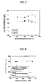
- FIG. 2 shows difference in strength of the consolidated products immediately after hot isostatic pressing, with the type of the carbide-forming additive element Zr, Ti, Nb or Mo.
- the Zr-, Ti- and Nb-added materials are improved in strength in comparison with the 0.12% C-added material (No. 5 in Table 1).
- Table 2 shows the carbonitrides identified by X-ray diffractometry. It is seen that M 23 (C, N) 6 carbonitride alone is observed in the 0.12% C-added material (No.5 in Table 1) and in the V- and Mo-added materials (Nos. 9 and 10, respectively, in Table 1), whereas M 23 (C, N) 6 carbonitride as well as M (C, N) carbonitride are observed in the Zr-, Ti- and Nb-added materials (No. 6, 7 and 8, respectively, in Table 1). This shows that the presence of M (C, N) carbonitride contributes to the improvement of strength.
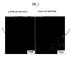
- the structure of the Zr-added material (No. 6 in Table 1) is shown in FIG. 3.
- the crystal grains 9 in this material are finer than the non-added material (No. 1 in Table 1).
- No. Carbonitrides identified by X-ray diffractometry 1 M 23 (C,N) 6 5 M 23 (C,N) 6 6 Zr(C,N), M 23 (C,N) 6 7 Ti(C,N), M 23 (C,N) 6 8 Nb(C,N), M 23 (C,N) 6 9 M 23 (C,N) 6 10 M 23 (C,N) 6
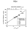
- the relationship between strength and crystal grain size shown in FIG. 4 is substantially in accord with Hall-Petch relationship, which indicates that grain refinement is the main factor of strengthening.
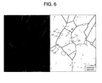
- the microscopic structure of the non-added material shows that M 23 (C, N) 6 carbonitride 13 was dispersed at the crystal grain boundaries 10 and in the inside 11 of the crystal grains as shown in FIG. 6, the grain size of the carbonitride in the crystal grains being several tens to 100 nm and that of the carbonitride at the crystal grain boundaries being 100 to 200 nm.
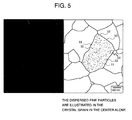
- the fine grains of M (C ,N) and M 23 (C, N) 6 carbonitrides 10 such as shown in FIG. 5 are precipitated and dispersed to pin intergranular transfer, with the result that the grain growth during the consolidation process is controlled and a finer structure can be obtained.
- the temperature at which the precipitation of carbonitride begins is lower than the temperature at which the grain growth is promoted.
- the temperatures from 400 to 650°C are the temperature zone in which the grain growth is not promoted but the carbonitrides are precipitated, so that by effecting sufficient precipitation of the carbonitrides by keeping the temperature within the range, it is possible to control the grain growth in the ensuing high temperature process to provide high strength.
- Table 3 shows the mechanical properties of the consolidated products subjected to hot isostatic pressing process and then hot forging at 850°C.
- a diagrammatic illustration of comparison with the conventional materials regarding toughness and tensile strength is shown in FIG. 8. Toughness was evaluated by absorbed energy determined by the V-notched Charpy impact test pieces.
- Conventional material (indicated by shadowed rhombi in FIG. 8) was a solid soluted material of austenitic stainless steel with a composition of 18% Cr and close to 8% Ni (compositions of Nos. 22 to 26 in Table 1);
- Conventional material 2 (indicated by unshadowed rhomb in FIG. 8) was a cold worked material of austenitic stainless steel (composition of No. 22 in Table 1); and
- Conventional material 3 (indicated by shadowed triangle) was semi-austenitic precipitation hardened stainless steel (composition of No. 27 in Table 1).
- the conventional materials would prove low in toughness if they were provided with high strength, but the steel material according to the present invention is high in both strength and toughness. Some conventional materials are within the same range of composition as the material according to the present invention, but they are low in strength because of their coarse structure due to the difference in the manufacturing process. Although the conventional material of No. 1 (comparative material) has an improved strength by cold working, it is low in toughness.
- FIG. 9 shows the result of evaluation of corrosion resistance of the material according to the present invention by determination of anode polarization curve in a sulfuric acid solution (1N, 30°C).
- the material according to the present invention (for example, No. 7 in Table 1) is low in critical passivation current density and passive state maintaining current density in comparison with the conventional materials. This indicates that the material according to the present invention exhibits higher corrosion resistance than the conventional materials at a potential in or lower than the passive region.
- FIG. 10 A perspective view of the testing apparatus is shown in FIG. 10.
- a plate-like test piece 14 was held between rounded holders 16 together with a spacing piece of glass fiber wool 15 and bolts were passed through bolt holes 17 and fastened.
- This assembly was immersed in an autoclave filled with high-temperature (288°C) and high-pressure (85 kg/cm 2 ) pure water (with 8 ppm of oxygen dissolved therein). The immersion time was 500 hours.
- each test piece was checked for cracks by its sectional observation under a light microscope. As a result, no crack was observed in all of the test pieces of the materials according to the present invention.
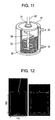
- an attrition mill shown in FIG. 11 was used for mechanical milling.
- This attrition mill comprised a stainless crushing tank 18 with a capacity of 25 liters, a cooling water inlet 19 of the tank 18, a cooling water outlet 20, a gas seal 21 for sealing a replacing gas such as argon or nitrogen gas, 10 mm-diameter crushing steel balls 23 placed in the tank, and an agitator arm 24. 5 kg of starting powder 22 was contained in the tank.
- a pre-alloy powder corresponding to No. 11 in Table 1 was used as starting powder 22.
- Rotating force was transmitted to arm shaft 25 from an outside driving system to rotate agitator arm 24.
- Steel balls 23 were agitated by said rotating agitator arm 24 so that these steel balls 23 collide against each other or against the inner wall of tank 18, whereby mixed powder 22 was forcibly processed to produce an alloy powder composed of fine crystal grains.
- the speed of arm shaft 25 was set at 150 rpm, and the treating time was 50 hours.
- Example 2 2.8 kg of a mechanically milled powder produced according to the process of Example 2 was vacuum sealed in the mild steel capsules and then consolidated by hot direct powder extrusion. In the extrusion process, the powder was once held at close to 600°C for 2 hours and then at 750°C, 800°C and 850°C for one hour each, and thereafter extruded from a die set at an extrusion ratio of 5.7.
- the relation of the consolidation temperature to the density of the consolidated product is shown in FIG. 15.
- the consolidated product obtained by hot isostatic pressing of 196 MPa it was necessary to raise the consolidation temperature to 800°C or above for compacting the product to substantially the same density as the ingot steel, but in the case of the consolidated product made by hot extrusion, it was possible to obtain substantially the same density as the ingot steel even at a consolidating temperature of 750°C.
- Example 3 The consolidated product made in Example 3 was cut into a disc, and the disc was heated to 750°C, then held in a heated mold and compressed by a press. It was confirmed that a part of such complicate configuration as shown in FIG. 16 could be produced with a lower compressive force than required for ingot steel.
- a bulk material of austenitic stainless steel can be obtained by consolidating a powder having its structure ultra-fined by mechanical milling while controlling the crystal grain growth.
- Such bulk material has higher strength and higher corrosion resistance with less reduction of toughness than that obtainable with the conventional methods, and in such bulk material, the nano scale fine crystal grain structure is uniformly distributed and its properties are uniformalized throughout the whole material.
Landscapes
- Chemical & Material Sciences (AREA)
- Engineering & Computer Science (AREA)
- Materials Engineering (AREA)
- Mechanical Engineering (AREA)
- Metallurgy (AREA)
- Organic Chemistry (AREA)
- Powder Metallurgy (AREA)
- Manufacture Of Metal Powder And Suspensions Thereof (AREA)
Applications Claiming Priority (2)
| Application Number | Priority Date | Filing Date | Title |
|---|---|---|---|
| JP2001052335 | 2001-02-27 | ||
| JP2001052335A JP3689009B2 (ja) | 2001-02-27 | 2001-02-27 | 高耐食性高強度オーステナイト系ステンレス鋼とその製法 |
Publications (2)
| Publication Number | Publication Date |
|---|---|
| EP1234894A1 true EP1234894A1 (de) | 2002-08-28 |
| EP1234894B1 EP1234894B1 (de) | 2007-07-18 |
Family
ID=18912984
Family Applications (1)
| Application Number | Title | Priority Date | Filing Date |
|---|---|---|---|
| EP02004277A Expired - Lifetime EP1234894B1 (de) | 2001-02-27 | 2002-02-27 | Korrosionsbeständige, hochfeste Legierung und Herstellungsverfahren |
Country Status (4)
| Country | Link |
|---|---|
| US (1) | US6767416B2 (de) |
| EP (1) | EP1234894B1 (de) |
| JP (1) | JP3689009B2 (de) |
| DE (1) | DE60221173T2 (de) |
Cited By (11)
| Publication number | Priority date | Publication date | Assignee | Title |
|---|---|---|---|---|
| EP1295958A1 (de) * | 2001-09-21 | 2003-03-26 | Hitachi, Ltd. | Ferritischer Stahl mit hoher Festigkeit und Zähigkeit und Verfahren zu dessen Herstellung |
| RU2215815C1 (ru) * | 2002-11-18 | 2003-11-10 | Закрытое акционерное общество "Ижевский опытно-механический завод" | Коррозионно-стойкая сталь |
| WO2004029313A1 (ja) * | 2002-09-30 | 2004-04-08 | Nano Technology Institute, Inc | 高硬度・高強度で強靭なナノ結晶金属バルク材及びその製造方法 |
| WO2004029312A1 (ja) * | 2002-09-27 | 2004-04-08 | Nano Technology Institute, Inc | 超硬質・強靭で優れた耐食性を有するナノ結晶オ−ステナイト鋼バルク材及びその製造方法 |
| EP1469095A1 (de) * | 2003-04-14 | 2004-10-20 | General Electric Company | Dispersionsgehärtete ausscheidungshärtbare Nickel-Eisen-Chromlegierung und zugehöriges Verfahren |
| FR2864108A1 (fr) * | 2003-12-22 | 2005-06-24 | Ugine Et Alz France | Tole en acier inoxydable presentant une grande resistance et un bon allongement, et procede de fabrication |
| RU2427451C2 (ru) * | 2009-11-16 | 2011-08-27 | Федеральное Государственное Унитарное Предприятие "Центральный Научно-Исследовательский Институт Конструкционных Материалов "Прометей" (Фгуп "Цнии Км "Прометей") | Способ получения нанокристаллического магнитного порошка для создания широкополосных радиопоглощающих материалов |
| US20120125067A1 (en) * | 2009-05-14 | 2012-05-24 | National Institute For Materials Science | Orifice plate and manufacturing method of the orifice plate |
| CN105772700A (zh) * | 2015-01-09 | 2016-07-20 | 精工爱普生株式会社 | 粉末冶金用金属粉末、复合物、造粒粉末以及烧结体 |
| CN110306104A (zh) * | 2019-08-06 | 2019-10-08 | 华北理工大学 | 一种耐腐蚀合金及其制备方法 |
| CN112935265A (zh) * | 2021-01-25 | 2021-06-11 | 北京科技大学 | 一种高强度粉末奥氏体不锈钢的制备方法 |
Families Citing this family (25)
| Publication number | Priority date | Publication date | Assignee | Title |
|---|---|---|---|---|
| US8562664B2 (en) * | 2001-10-25 | 2013-10-22 | Advanced Cardiovascular Systems, Inc. | Manufacture of fine-grained material for use in medical devices |
| JP4325521B2 (ja) * | 2004-09-28 | 2009-09-02 | 住友金属工業株式会社 | ガスケット用ステンレス鋼板とその製造方法 |
| US20060275168A1 (en) * | 2005-06-03 | 2006-12-07 | Ati Properties, Inc. | Austenitic stainless steel |
| US9040865B2 (en) * | 2007-02-27 | 2015-05-26 | Exxonmobil Upstream Research Company | Corrosion resistant alloy weldments in carbon steel structures and pipelines to accommodate high axial plastic strains |
| US8430075B2 (en) * | 2008-12-16 | 2013-04-30 | L.E. Jones Company | Superaustenitic stainless steel and method of making and use thereof |
| US8479700B2 (en) * | 2010-01-05 | 2013-07-09 | L. E. Jones Company | Iron-chromium alloy with improved compressive yield strength and method of making and use thereof |
| JP5585237B2 (ja) * | 2010-06-24 | 2014-09-10 | セイコーエプソン株式会社 | 粉末冶金用金属粉末および焼結体 |
| RU2484170C1 (ru) * | 2012-05-18 | 2013-06-10 | Федеральное государственное бюджетное образовательное учреждение высшего профессионального образования "Санкт-Петербургский государственный политехнический университет" (ФГБОУ ВПО "СПбГПУ") | Способ получения высокоазотистой аустенитной порошковой стали с нанокристаллической структурой |
| JP6354592B2 (ja) * | 2014-03-04 | 2018-07-11 | セイコーエプソン株式会社 | 粉末冶金用金属粉末、コンパウンド、造粒粉末および焼結体 |
| JP6319110B2 (ja) * | 2014-03-26 | 2018-05-09 | セイコーエプソン株式会社 | 粉末冶金用金属粉末、コンパウンド、造粒粉末、焼結体および焼結体の製造方法 |
| EP3168317A1 (de) * | 2014-07-07 | 2017-05-17 | Hitachi, Ltd. | Austenitischer edelstahl und verfahren zur herstellung davon |
| US10179943B2 (en) | 2014-07-18 | 2019-01-15 | General Electric Company | Corrosion resistant article and methods of making |
| JP6308123B2 (ja) * | 2014-12-16 | 2018-04-11 | セイコーエプソン株式会社 | 粉末冶金用金属粉末、コンパウンド、造粒粉末および焼結体 |
| CN104593692B (zh) * | 2014-12-24 | 2017-01-04 | 北京科技大学 | 一种具有优异高温综合性能的耐热铸造奥氏体不锈钢 |
| JP6314842B2 (ja) * | 2015-01-06 | 2018-04-25 | セイコーエプソン株式会社 | 粉末冶金用金属粉末、コンパウンド、造粒粉末および焼結体 |
| JP6314866B2 (ja) * | 2015-02-09 | 2018-04-25 | セイコーエプソン株式会社 | 粉末冶金用金属粉末、コンパウンド、造粒粉末および焼結体の製造方法 |
| CN104651731B (zh) * | 2015-02-12 | 2016-07-06 | 北京工业大学 | 一种大型球磨机衬板及其制备方法 |
| WO2017073422A1 (ja) * | 2015-10-30 | 2017-05-04 | 株式会社日立製作所 | 分散強化型オーステナイト系ステンレス鋼材、該ステンレス鋼材の製造方法および該ステンレス鋼材からなる製造物 |
| WO2018186424A1 (ja) | 2017-04-03 | 2018-10-11 | 王子ホールディングス株式会社 | ポリプロピレンフィルム、金属層一体型ポリプロピレンフィルムおよびフィルムコンデンサ |
| KR102468929B1 (ko) | 2017-04-03 | 2022-11-21 | 오지 홀딩스 가부시키가이샤 | 폴리프로필렌 필름, 금속층 일체형 폴리프로필렌 필름 및 필름 콘덴서 |
| JP7141251B2 (ja) * | 2018-06-06 | 2022-09-22 | 株式会社日立製作所 | オーステナイト系ステンレス鋼及び原子炉内構造物 |
| CN109439853A (zh) * | 2018-11-01 | 2019-03-08 | 天津中德应用技术大学 | 新型低合金超高强度钢及形变热处理工艺 |
| CN110241364B (zh) * | 2019-07-19 | 2021-03-26 | 东北大学 | 一种高强塑纳米/亚微米晶冷轧304不锈钢带及其制备方法 |
| CN113231648B (zh) * | 2021-04-29 | 2022-08-19 | 西安建筑科技大学 | 一种高强度奥氏体不锈钢及其制备方法 |
| CN113500196B (zh) * | 2021-07-14 | 2023-04-18 | 燕山大学 | 一种通过调控Si的纳米网络分布提高奥氏体不锈钢抗高温氧化性的方法 |
Citations (7)
| Publication number | Priority date | Publication date | Assignee | Title |
|---|---|---|---|---|
| US4770703A (en) * | 1984-06-06 | 1988-09-13 | Sumitomo Metal Industries, Ltd. | Sintered stainless steel and production process therefor |
| JPH08269547A (ja) * | 1995-03-27 | 1996-10-15 | Nippon Steel Corp | 超電導材生成熱処理後の極低温特性の優れたステンレス鋼板の製造方法 |
| EP0747497A1 (de) * | 1995-06-09 | 1996-12-11 | Hitachi, Ltd. | Hochfester, korrosionsbeständiger austenitischer Stahl geeignet für Kernreaktorteile und dessen Herstellung |
| JPH1088289A (ja) * | 1996-09-12 | 1998-04-07 | Hitachi Ltd | 高耐食性高強度Cr−Mn系オーステナイト焼結鋼とその製造方法及びその用途 |
| EP0834580A1 (de) * | 1996-04-16 | 1998-04-08 | Nippon Steel Corporation | Legierung mit hoher korrosionsbeständigkeit in stark korrosiver umbegung, stahlrohr aus der legierung und herstellungsverfahren des stahlrohres |
| JPH10195502A (ja) * | 1997-01-09 | 1998-07-28 | Ritsumeikan | ステンレス鋼粉末、ステンレス鋼部材及び該ステンレス鋼部材の製造方法 |
| JPH1143748A (ja) * | 1997-07-23 | 1999-02-16 | Hitachi Ltd | 高強度オーステナイト焼結鋼とその製造方法及びその用途 |
Family Cites Families (3)
| Publication number | Priority date | Publication date | Assignee | Title |
|---|---|---|---|---|
| US3620690A (en) * | 1968-07-10 | 1971-11-16 | Minnesota Mining & Mfg | Sintered austenitic-ferritic chromium-nickel steel alloy |
| JPS5814847B2 (ja) * | 1977-10-03 | 1983-03-22 | 石川島播磨重工業株式会社 | オ−ステナイトステンレス鋼の結晶粒微細化方法 |
| US5908486A (en) * | 1996-04-26 | 1999-06-01 | Lockheed Martin Idaho Technologies Company | Strengthening of metallic alloys with nanometer-size oxide dispersions |
-
2001
- 2001-02-27 JP JP2001052335A patent/JP3689009B2/ja not_active Expired - Lifetime
-
2002
- 2002-02-27 DE DE60221173T patent/DE60221173T2/de not_active Expired - Lifetime
- 2002-02-27 EP EP02004277A patent/EP1234894B1/de not_active Expired - Lifetime
- 2002-02-27 US US10/083,544 patent/US6767416B2/en not_active Expired - Lifetime
Patent Citations (7)
| Publication number | Priority date | Publication date | Assignee | Title |
|---|---|---|---|---|
| US4770703A (en) * | 1984-06-06 | 1988-09-13 | Sumitomo Metal Industries, Ltd. | Sintered stainless steel and production process therefor |
| JPH08269547A (ja) * | 1995-03-27 | 1996-10-15 | Nippon Steel Corp | 超電導材生成熱処理後の極低温特性の優れたステンレス鋼板の製造方法 |
| EP0747497A1 (de) * | 1995-06-09 | 1996-12-11 | Hitachi, Ltd. | Hochfester, korrosionsbeständiger austenitischer Stahl geeignet für Kernreaktorteile und dessen Herstellung |
| EP0834580A1 (de) * | 1996-04-16 | 1998-04-08 | Nippon Steel Corporation | Legierung mit hoher korrosionsbeständigkeit in stark korrosiver umbegung, stahlrohr aus der legierung und herstellungsverfahren des stahlrohres |
| JPH1088289A (ja) * | 1996-09-12 | 1998-04-07 | Hitachi Ltd | 高耐食性高強度Cr−Mn系オーステナイト焼結鋼とその製造方法及びその用途 |
| JPH10195502A (ja) * | 1997-01-09 | 1998-07-28 | Ritsumeikan | ステンレス鋼粉末、ステンレス鋼部材及び該ステンレス鋼部材の製造方法 |
| JPH1143748A (ja) * | 1997-07-23 | 1999-02-16 | Hitachi Ltd | 高強度オーステナイト焼結鋼とその製造方法及びその用途 |
Non-Patent Citations (4)
| Title |
|---|
| PATENT ABSTRACTS OF JAPAN vol. 1997, no. 02 28 February 1997 (1997-02-28) * |
| PATENT ABSTRACTS OF JAPAN vol. 1998, no. 09 31 July 1998 (1998-07-31) * |
| PATENT ABSTRACTS OF JAPAN vol. 1998, no. 12 31 October 1998 (1998-10-31) * |
| PATENT ABSTRACTS OF JAPAN vol. 1999, no. 05 31 May 1999 (1999-05-31) * |
Cited By (23)
| Publication number | Priority date | Publication date | Assignee | Title |
|---|---|---|---|---|
| EP1295958A1 (de) * | 2001-09-21 | 2003-03-26 | Hitachi, Ltd. | Ferritischer Stahl mit hoher Festigkeit und Zähigkeit und Verfahren zu dessen Herstellung |
| US6827755B2 (en) | 2001-09-21 | 2004-12-07 | Hitachi, Ltd. | High-toughness and high-strength ferritic steel and method of producing the same |
| EP1555332A4 (de) * | 2002-09-27 | 2007-07-11 | Nano Technology Inst Inc | Nanokristallines austenitstahl-bulkmaterial mit ultrahärte, zähigkeit und hervorragender korrosionsbeständigkeit sowie zugehöriges herstellungsverfahren |
| US7662207B2 (en) | 2002-09-27 | 2010-02-16 | Nano Technology Institiute, Inc. | Nano-crystal austenitic steel bulk material having ultra-hardness and toughness and excellent corrosion resistance, and method for production thereof |
| RU2324757C2 (ru) * | 2002-09-27 | 2008-05-20 | Нано Текнолоджи Инститьют, Инк. | Нанокристаллический материал со структурой аустенитной стали, обладающий высокой твердостью, прочностью и коррозионной стойкостью, и способ его изготовления |
| WO2004029312A1 (ja) * | 2002-09-27 | 2004-04-08 | Nano Technology Institute, Inc | 超硬質・強靭で優れた耐食性を有するナノ結晶オ−ステナイト鋼バルク材及びその製造方法 |
| RU2324576C2 (ru) * | 2002-09-30 | 2008-05-20 | Нано Текнолоджи Инститьют, Инк | Нанокристаллический металлический материал с аустенитной структурой, обладающий высокой твердостью, прочностью и вязкостью, и способ его изготовления |
| EP1548138A4 (de) * | 2002-09-30 | 2007-07-18 | Nano Technology Inst Inc | Nanokristallines austenitmetall-bulkmaterial mit hoher härte, hoher festigkeit und zähigkeit und herstellungsverfahren dafür |
| WO2004029313A1 (ja) * | 2002-09-30 | 2004-04-08 | Nano Technology Institute, Inc | 高硬度・高強度で強靭なナノ結晶金属バルク材及びその製造方法 |
| RU2215815C1 (ru) * | 2002-11-18 | 2003-11-10 | Закрытое акционерное общество "Ижевский опытно-механический завод" | Коррозионно-стойкая сталь |
| EP1469095A1 (de) * | 2003-04-14 | 2004-10-20 | General Electric Company | Dispersionsgehärtete ausscheidungshärtbare Nickel-Eisen-Chromlegierung und zugehöriges Verfahren |
| CN100410404C (zh) * | 2003-04-14 | 2008-08-13 | 通用电气公司 | 沉淀强化的镍-铁-铬合金及其生产方法 |
| KR100917482B1 (ko) | 2003-04-14 | 2009-09-16 | 제너럴 일렉트릭 캄파니 | 석출 강화된 니켈-철-크롬 합금 및 이의 제조방법 |
| US7118636B2 (en) | 2003-04-14 | 2006-10-10 | General Electric Company | Precipitation-strengthened nickel-iron-chromium alloy |
| FR2864108A1 (fr) * | 2003-12-22 | 2005-06-24 | Ugine Et Alz France | Tole en acier inoxydable presentant une grande resistance et un bon allongement, et procede de fabrication |
| US9366211B2 (en) * | 2009-05-14 | 2016-06-14 | National Institute For Materials Science | Orifice plate and manufacturing method of the orifice plate |
| US20120125067A1 (en) * | 2009-05-14 | 2012-05-24 | National Institute For Materials Science | Orifice plate and manufacturing method of the orifice plate |
| RU2427451C2 (ru) * | 2009-11-16 | 2011-08-27 | Федеральное Государственное Унитарное Предприятие "Центральный Научно-Исследовательский Институт Конструкционных Материалов "Прометей" (Фгуп "Цнии Км "Прометей") | Способ получения нанокристаллического магнитного порошка для создания широкополосных радиопоглощающих материалов |
| CN105772700A (zh) * | 2015-01-09 | 2016-07-20 | 精工爱普生株式会社 | 粉末冶金用金属粉末、复合物、造粒粉末以及烧结体 |
| CN105772700B (zh) * | 2015-01-09 | 2019-11-26 | 精工爱普生株式会社 | 粉末冶金用金属粉末、复合物、造粒粉末以及烧结体 |
| CN110306104A (zh) * | 2019-08-06 | 2019-10-08 | 华北理工大学 | 一种耐腐蚀合金及其制备方法 |
| CN110306104B (zh) * | 2019-08-06 | 2021-07-06 | 华北理工大学 | 一种耐腐蚀合金及其制备方法 |
| CN112935265A (zh) * | 2021-01-25 | 2021-06-11 | 北京科技大学 | 一种高强度粉末奥氏体不锈钢的制备方法 |
Also Published As
| Publication number | Publication date |
|---|---|
| DE60221173T2 (de) | 2008-04-10 |
| JP2002256400A (ja) | 2002-09-11 |
| JP3689009B2 (ja) | 2005-08-31 |
| US20020164259A1 (en) | 2002-11-07 |
| EP1234894B1 (de) | 2007-07-18 |
| US6767416B2 (en) | 2004-07-27 |
| DE60221173D1 (de) | 2007-08-30 |
Similar Documents
| Publication | Publication Date | Title |
|---|---|---|
| US6767416B2 (en) | Corrosion resistant, high strength alloy and a method for manufacturing the same | |
| JP7601463B2 (ja) | 高エントロピーのオーステナイト系ステンレス鋼及びその製造方法 | |
| US6827755B2 (en) | High-toughness and high-strength ferritic steel and method of producing the same | |
| Cheng et al. | Microstructure and mechanical properties of FeCoCrNiMn high-entropy alloy produced by mechanical alloying and vacuum hot pressing sintering | |
| US8409497B2 (en) | Hot and cold rolling high strength L12 aluminum alloys | |
| US7922841B2 (en) | Method for preparing high-temperature nanophase aluminum-alloy sheets and aluminum-alloy sheets prepared thereby | |
| US20100143177A1 (en) | Method for forming high strength aluminum alloys containing L12 intermetallic dispersoids | |
| JP4652490B2 (ja) | 統合粉末冶金法により製造したスチールとその熱処理工具及び該スチールの工具への使用 | |
| US20100226817A1 (en) | High strength l12 aluminum alloys produced by cryomilling | |
| Gao et al. | Microstructure evolution and strengthening mechanism of high-performance powder metallurgy TA15 titanium alloy by hot rolling | |
| Zhao | In situ thermomechanical processing to avoid grain boundary precipitation and strength-ductility loss of age hardening alloys | |
| Oksiuta et al. | Optimization of the chemical composition and manufacturing route for ODS RAF steels for fusion reactor application | |
| EP2253725B1 (de) | Direktschmieden und -walzen von L12-Aluminiumlegierungen für Panzerungsanwendungen | |
| CN113073274A (zh) | 一种新型制备双相超细晶高熵合金的方法 | |
| JP3020924B1 (ja) | 高強度高耐食性フェライト鋼の製造方法 | |
| JPH1143748A (ja) | 高強度オーステナイト焼結鋼とその製造方法及びその用途 | |
| JP4281857B2 (ja) | 焼結工具鋼及びその製造方法 | |
| CN116065101B (zh) | 无钴钢、制备方法及应用 | |
| JP2005281768A (ja) | 高硬度のナノ結晶白鋳鉄粉末及び高硬度・高強度で強靱なナノ結晶白鋳鉄バルク材並びにその製造方法 | |
| Lei et al. | Bulk nanocrystalline Al–Mg–Y alloys with amorphous grain boundary complexions display high strength and compressive plasticity | |
| CN116536583A (zh) | 性能均匀且热处理前后三维尺寸稳定模具钢及其制备方法 | |
| Si et al. | Towards high strain-hardening capability through precipitating coherent L12 nanoprecipitates in non-equiatomic CoVFe medium entropy alloys | |
| WO2005092542A1 (ja) | 高硬度の高炭素ナノ結晶鉄合金粉末及びバルク材並びにその製造方法 | |
| Jiménez et al. | Microstructural and mechanical characterisation of composite materials consisting of M3/2 high speed steel reinforced with niobium carbides | |
| EP4450186A1 (de) | Verwaltung von stahlpulver frei von co, ti und al |
Legal Events
| Date | Code | Title | Description |
|---|---|---|---|
| PUAI | Public reference made under article 153(3) epc to a published international application that has entered the european phase |
Free format text: ORIGINAL CODE: 0009012 |
|
| AK | Designated contracting states |
Kind code of ref document: A1 Designated state(s): AT BE CH CY DE DK ES FI FR GB GR IE IT LI LU MC NL PT SE TR |
|
| AX | Request for extension of the european patent |
Free format text: AL;LT;LV;MK;RO;SI |
|
| 17P | Request for examination filed |
Effective date: 20021216 |
|
| AKX | Designation fees paid |
Designated state(s): DE FR GB SE |
|
| GRAP | Despatch of communication of intention to grant a patent |
Free format text: ORIGINAL CODE: EPIDOSNIGR1 |
|
| GRAS | Grant fee paid |
Free format text: ORIGINAL CODE: EPIDOSNIGR3 |
|
| GRAA | (expected) grant |
Free format text: ORIGINAL CODE: 0009210 |
|
| RIN1 | Information on inventor provided before grant (corrected) |
Inventor name: AONO, YASUHISA,HITACHI,LTD., INTELL.PROP.GROUP Inventor name: ISHIBASHI, RYO,HITACHI,LTD., INTELL.PROP.GROUP |
|
| RAP1 | Party data changed (applicant data changed or rights of an application transferred) |
Owner name: HITACHI, LTD. |
|
| AK | Designated contracting states |
Kind code of ref document: B1 Designated state(s): DE FR GB SE |
|
| REG | Reference to a national code |
Ref country code: GB Ref legal event code: FG4D |
|
| REF | Corresponds to: |
Ref document number: 60221173 Country of ref document: DE Date of ref document: 20070830 Kind code of ref document: P |
|
| REG | Reference to a national code |
Ref country code: SE Ref legal event code: TRGR |
|
| ET | Fr: translation filed | ||
| PLBE | No opposition filed within time limit |
Free format text: ORIGINAL CODE: 0009261 |
|
| STAA | Information on the status of an ep patent application or granted ep patent |
Free format text: STATUS: NO OPPOSITION FILED WITHIN TIME LIMIT |
|
| 26N | No opposition filed |
Effective date: 20080421 |
|
| PGFP | Annual fee paid to national office [announced via postgrant information from national office to epo] |
Ref country code: SE Payment date: 20140211 Year of fee payment: 13 |
|
| PGFP | Annual fee paid to national office [announced via postgrant information from national office to epo] |
Ref country code: DE Payment date: 20140417 Year of fee payment: 13 |
|
| REG | Reference to a national code |
Ref country code: DE Ref legal event code: R119 Ref document number: 60221173 Country of ref document: DE |
|
| REG | Reference to a national code |
Ref country code: SE Ref legal event code: EUG |
|
| PG25 | Lapsed in a contracting state [announced via postgrant information from national office to epo] |
Ref country code: SE Free format text: LAPSE BECAUSE OF NON-PAYMENT OF DUE FEES Effective date: 20150228 |
|
| REG | Reference to a national code |
Ref country code: FR Ref legal event code: PLFP Year of fee payment: 15 |
|
| PG25 | Lapsed in a contracting state [announced via postgrant information from national office to epo] |
Ref country code: DE Free format text: LAPSE BECAUSE OF NON-PAYMENT OF DUE FEES Effective date: 20150901 |
|
| PGFP | Annual fee paid to national office [announced via postgrant information from national office to epo] |
Ref country code: GB Payment date: 20160224 Year of fee payment: 15 Ref country code: FR Payment date: 20160108 Year of fee payment: 15 |
|
| GBPC | Gb: european patent ceased through non-payment of renewal fee |
Effective date: 20170227 |
|
| REG | Reference to a national code |
Ref country code: FR Ref legal event code: ST Effective date: 20171031 |
|
| PG25 | Lapsed in a contracting state [announced via postgrant information from national office to epo] |
Ref country code: FR Free format text: LAPSE BECAUSE OF NON-PAYMENT OF DUE FEES Effective date: 20170228 |
|
| PG25 | Lapsed in a contracting state [announced via postgrant information from national office to epo] |
Ref country code: GB Free format text: LAPSE BECAUSE OF NON-PAYMENT OF DUE FEES Effective date: 20170227 |