EP1235323A1 - Alimentation pour ascenseur a ca - Google Patents
Alimentation pour ascenseur a ca Download PDFInfo
- Publication number
- EP1235323A1 EP1235323A1 EP00976270A EP00976270A EP1235323A1 EP 1235323 A1 EP1235323 A1 EP 1235323A1 EP 00976270 A EP00976270 A EP 00976270A EP 00976270 A EP00976270 A EP 00976270A EP 1235323 A1 EP1235323 A1 EP 1235323A1
- Authority
- EP
- European Patent Office
- Prior art keywords
- battery
- power source
- source device
- charge
- elevator according
- Prior art date
- Legal status (The legal status is an assumption and is not a legal conclusion. Google has not performed a legal analysis and makes no representation as to the accuracy of the status listed.)
- Withdrawn
Links
Images








Classifications
-
- H—ELECTRICITY
- H02—GENERATION; CONVERSION OR DISTRIBUTION OF ELECTRIC POWER
- H02J—ELECTRIC POWER NETWORKS; CIRCUIT ARRANGEMENTS OR SYSTEMS FOR SUPPLYING OR DISTRIBUTING ELECTRIC POWER; SYSTEMS FOR STORING ELECTRIC ENERGY
- H02J7/00—Circuit arrangements for charging or discharging batteries or for supplying loads from batteries
- H02J7/34—Parallel operation in networks using both storage and other DC sources, e.g. providing buffering
-
- B—PERFORMING OPERATIONS; TRANSPORTING
- B66—HOISTING; LIFTING; HAULING
- B66B—ELEVATORS; ESCALATORS OR MOVING WALKWAYS
- B66B1/00—Control systems of elevators in general
- B66B1/24—Control systems with regulation, i.e. with retroactive action, for influencing travelling speed, acceleration, or deceleration
- B66B1/28—Control systems with regulation, i.e. with retroactive action, for influencing travelling speed, acceleration, or deceleration electrical
- B66B1/30—Control systems with regulation, i.e. with retroactive action, for influencing travelling speed, acceleration, or deceleration electrical effective on driving gear, e.g. acting on power electronics, on inverter or rectifier controlled motor
-
- H—ELECTRICITY
- H02—GENERATION; CONVERSION OR DISTRIBUTION OF ELECTRIC POWER
- H02J—ELECTRIC POWER NETWORKS; CIRCUIT ARRANGEMENTS OR SYSTEMS FOR SUPPLYING OR DISTRIBUTING ELECTRIC POWER; SYSTEMS FOR STORING ELECTRIC ENERGY
- H02J7/00—Circuit arrangements for charging or discharging batteries or for supplying loads from batteries
- H02J7/80—Circuit arrangements for charging or discharging batteries or for supplying loads from batteries including monitoring or indicating arrangements
- H02J7/84—Control of state of health [SOH]
-
- H—ELECTRICITY
- H02—GENERATION; CONVERSION OR DISTRIBUTION OF ELECTRIC POWER
- H02J—ELECTRIC POWER NETWORKS; CIRCUIT ARRANGEMENTS OR SYSTEMS FOR SUPPLYING OR DISTRIBUTING ELECTRIC POWER; SYSTEMS FOR STORING ELECTRIC ENERGY
- H02J7/00—Circuit arrangements for charging or discharging batteries or for supplying loads from batteries
- H02J7/90—Regulation of charging or discharging current or voltage
- H02J7/96—Regulation of charging or discharging current or voltage in response to battery voltage
-
- H—ELECTRICITY
- H02—GENERATION; CONVERSION OR DISTRIBUTION OF ELECTRIC POWER
- H02J—ELECTRIC POWER NETWORKS; CIRCUIT ARRANGEMENTS OR SYSTEMS FOR SUPPLYING OR DISTRIBUTING ELECTRIC POWER; SYSTEMS FOR STORING ELECTRIC ENERGY
- H02J9/00—Circuit arrangements for emergency or stand-by power supply, e.g. for emergency lighting
- H02J9/04—Circuit arrangements for emergency or stand-by power supply, e.g. for emergency lighting in which the distribution system is disconnected from the normal source and connected to a standby source
- H02J9/06—Circuit arrangements for emergency or stand-by power supply, e.g. for emergency lighting in which the distribution system is disconnected from the normal source and connected to a standby source with automatic change-over, e.g. UPS systems
- H02J9/062—Circuit arrangements for emergency or stand-by power supply, e.g. for emergency lighting in which the distribution system is disconnected from the normal source and connected to a standby source with automatic change-over, e.g. UPS systems for AC powered loads
-
- H—ELECTRICITY
- H02—GENERATION; CONVERSION OR DISTRIBUTION OF ELECTRIC POWER
- H02M—APPARATUS FOR CONVERSION BETWEEN AC AND AC, BETWEEN AC AND DC, OR BETWEEN DC AND DC, AND FOR USE WITH MAINS OR SIMILAR POWER SUPPLY SYSTEMS; CONVERSION OF DC OR AC INPUT POWER INTO SURGE OUTPUT POWER; CONTROL OR REGULATION THEREOF
- H02M3/00—Conversion of DC power input into DC power output
- H02M3/02—Conversion of DC power input into DC power output without intermediate conversion into AC
- H02M3/04—Conversion of DC power input into DC power output without intermediate conversion into AC by static converters
- H02M3/10—Conversion of DC power input into DC power output without intermediate conversion into AC by static converters using discharge tubes with control electrode or semiconductor devices with control electrode
- H02M3/145—Conversion of DC power input into DC power output without intermediate conversion into AC by static converters using discharge tubes with control electrode or semiconductor devices with control electrode using devices of a triode or transistor type requiring continuous application of a control signal
- H02M3/155—Conversion of DC power input into DC power output without intermediate conversion into AC by static converters using discharge tubes with control electrode or semiconductor devices with control electrode using devices of a triode or transistor type requiring continuous application of a control signal using semiconductor devices only
- H02M3/156—Conversion of DC power input into DC power output without intermediate conversion into AC by static converters using discharge tubes with control electrode or semiconductor devices with control electrode using devices of a triode or transistor type requiring continuous application of a control signal using semiconductor devices only with automatic control of output voltage or current, e.g. switching regulators
- H02M3/158—Conversion of DC power input into DC power output without intermediate conversion into AC by static converters using discharge tubes with control electrode or semiconductor devices with control electrode using devices of a triode or transistor type requiring continuous application of a control signal using semiconductor devices only with automatic control of output voltage or current, e.g. switching regulators including plural semiconductor devices as final control devices for a single load
- H02M3/1582—Buck-boost converters
Definitions
- the present invention relates to improvements in power source devices for a.c. elevators.
- elevators generally have a well bucket construction which comprises a rope 83 wound on a hoist 82 and provided with an elevator car 8 connected to one end thereof and a counterweight 81 connected to the other end thereof.
- the weight of the counterweight is so adjusted as to be in balance with a load corresponding to 40 to 50% of the rated movable load.
- inverter drive systems are placed into use which comprise an inverter 3 for supplying voltage-variable frequency-variable a.c. power to an induction motor of the hoist 82 as illustrated for speed control to lift and lower the elevator car 8.
- a method of returning the regenerative power to the power source using a converter comprising transistors and adapted to regenerate the power source and a method of dissipating into air the regenerative power as converted to heat by resistance.
- the former method is used chiefly for high-speed elevators in high-rise buildings, while the latter method is used for medium- to low-speed elevators in medium to low buildings.
- the converter for use in the former method exhibits a high conversion efficiency, affords a power factor of nearly 1, is therefore very excellent, but has the drawback of necessitating an expensive apparatus.
- the latter method is easy to control and inexpensive in apparatus, but has the problem of being low in energy utilizing efficiency since the regenerative power is released as heat.
- a power source device For use with electric motors for driving elevators, a power source device has been proposed which comprises a battery connected in parallel with a d.c. power supply unit of constant voltage and to be charged with regenerative power when the elevator motor is decelerated, such that the battery chiefly supplies current to the motor when the motor is accelerated [JP-B No. 53-4839(1978)].
- the proposed power source device there must be a specific corresponding relationship between the voltage regulation characteristics of the rectifying circuit for converting the a.c. output of the power source to direct current and the voltage regulation characteristics of the battery, whereas it is difficult to design a rectifying circuit and battery which will fulfill such a corresponding relationship.
- the proposed device has the problem of being difficult to realize.
- an object of the present invention is to provide a power source device for a.c. elevators which achieves a high energy utilization efficiency and which is nevertheless easy to realize.
- the present invention provides an a.c. elevator having a commercial power source, an inverter operable with the power from the commercial power source for generating a.c. power, and an electric motor to be driven with the a.c. power generated by the inverter.
- a power source device for the a.c. elevator comprises a rechargeable battery, a charge/discharge circuit for charging and discharging the battery, and a control circuit for controlling the voltage to be input to the inverter by controlling the operation of the charge/discharge circuit, the battery being chargeable with regenerative power from the electric motor, the battery being operable to generate power and supply the power to the inverter.
- the control circuit comprises voltage control means for controlling the input voltage of the inverter to a constant level.
- the charge/discharge circuit has a charge control element for closing a charge circuit and a discharge control element for closing a discharge circuit, and the charge control element and the discharge control element are on/off-controlled by the control circuit.
- the control circuit alternately turns on the charge control element and the discharge control element to alternately charge and discharge the battery. According to the charged state of the battery or the operating state of the elevator, the control circuit alters the on period of the charge control element and the on period of the discharge control element relative to each other to determine the priority of charging by the charge circuit or discharging by the discharge circuit.
- the input voltage of the inverter is controlled to a constant level. For example during the load lowering operation, regenerative power supplied from the motor via the inverter is delivered to the battery for charging, while during the load lifting operation, the power generated by the battery is supplied to the motor via the inverter.
- the control circuit comprises discharge restricting means for restricting the discharging of the battery and charge restricting means for restricting the charging of the battery.
- the charge restricting means of the control circuit prevents charging of the battery upon the charged state of the battery exceeding about 80% of the rated capacity thereof to thereby prevent overcharging.
- the discharge restricting means of the control circuit prevents discharging of the battery upon the charged state of the battery dropping below about 30% of the rated capacity thereof to thereby prevent overdischarging.
- the charge restricting means and the discharge restricting means of the control circuit comprises a limiter circuit for imposing limitation on the deviation of the input voltage of the inverter from the voltage command thereof.
- the charge-side limiter value of the limiter circuit is set to zero upon the charged state of the battery exceeding about 80% of the rated capacity thereof.
- the discharge-side limiter value of the limiter circuit is set to zero upon the charged state of the battery dropping below about 30% of the rated capacity thereof.
- the control circuit comprises a discharge preventing means for preventing discharging of the battery under a predetermined condition.
- the control circuit comprises a charge preventing means for preventing charging of the battery under a predetermined condition.
- the control circuit further comprises means for presetting capacity measuring means for measuring the capacity of the battery, upon completion of charging of the battery, and means for resetting capacity measuring means for measuring the capacity of the battery, upon completion of discharging of the battery, whereby an accumulated error of the capacity measuring means is eliminated.
- the control circuit comprises means for changing over discharging from the battery to constant-current control and changing over charging of the battery to constant-current control, and means for detecting the internal resistance of the battery based on the terminal voltage of the battery during discharging and the terminal voltage of the battery during charging. Accordingly, the life of the battery can be judged from the variation of the internal resistance.
- the power source device of the present invention comprises an output contact provided between an input terminal of the inverter and the control circuit and controllable for opening and closing, a comparator for comparing the input voltage of the inverter with the terminal voltage of the battery, and control means for closing the output contact upon said input voltage exceeding said terminal voltage, whereby rush current is suppressed when the output contact is closed.
- a rope 83 is wound on a hoist 82 to be driven by an induction motor 1M as shown in FIG. 2.
- An elevator car 8 is connected to one end of the rope 83, and a counterweight 81 to the other end of the rope 83.
- the a.c. power supplied from a commercial power source 1 is converted by a converter 2 to d.c. power, then input to an inverter 3 and converted to a.c. power.
- the inverter delivers an a.c. current to the induction motor 1M.
- the inverter 3 is controlled by a known PWM control circuit shown in FIG. 2. Stated more specifically, the inductor motor 1M is provided with a pulse generator PG for detecting the actual speed of the elevator car 8. A speed command 4 for the elevator car 8 and an output signal of the pulse generator PG are fed to a speed adjuster 5 to prepare a speed deviation signal, which is fed to a frequency-variable current command computing circuit 6. This circuit prepares a frequency-variable current command, which is fed to a sine wave PWM control circuit 7 for this circuit to prepare a PWM control signal. This signal is fed to the inverter 3 for the speed control of the elevator car 8.
- the inverter 3 has input terminals a, b, which have connected thereto a power source circuit 10 according to the invention.
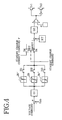
- the power source circuit 10 comprises a battery E comprising secondary cells such as nickel-hydrogen cells, and a pair of transistors Tr1 Tr2 and a pair of diodes D1, D2 for controlling the charging and discharging of the battery E.
- the battery E comprises a plurality of units in accordance with the capacity of the elevator, each of the units comprising eight cells B.
- the battery E has connected thereto a capacity meter Q for detecting the quantity of charge thereof, booster coil L and current detector RT.
- the capacity meter Q is described as being a hardware instrument connected to the battery E, the meter is not limited to such an instrument but can be measuring means as software for calculating the capacity from variations in the current detected by the current detector RT.
- FIG. 7 is a flow chart showing an example of procedure for realizing the capacity meter Q by software.
- a current input is received from the current detector RT in step S-41, and the current is processed for averaging in step S-42.
- an ampere-hour value is referred to in step S-43, and an inquiry is made in step S-44 as to whether the ampere-hour value is above 0. If the inquiry is answered in the negative, step S-45 follows to check whether the ampere-hour value is lower than 0. If the answer is affirmative, step S-46 follows to calculate the amount of discharge. If the inquiry of step S-44 is answered in the affirmative, on the other hand, step S-47 follows to calculate the amount of charge. Subsequently step S-48 calculates the capacity in percentage from the result of calculation of the discharge amount or charge amount, and the calculated capacity is fed to a capacity memory in step S49.
- the battery E has connected thereto an emergency power source supply circuit 11 serving as a control power source for supplying the power of the battery E in an event of a power failure or like emergency, and an emergency contact 12 to be opened in the event of malfunctioning of the power source circuit 10.
- an emergency power source supply circuit 11 serving as a control power source for supplying the power of the battery E in an event of a power failure or like emergency
- an emergency contact 12 to be opened in the event of malfunctioning of the power source circuit 10.
- FIG. 3 shows a control system realized by the power source circuit 10 and the control circuit 9.
- the input voltage Vab of the inverter 3 is negatively fed back, and the deviation signal e is passed through a transfer function G1 and limiter circuit 20 to prepare a current command i.
- a current value from the current detector RT is negatively fed back to the current command i, and the deviation signal is input to a comparator 21 via a transfer function G2.
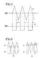
- the comparator 21 compares triangular waves ⁇ from a triangular wave generator 22 and an output signal from the transfer function G2 to prepare a control signal C for the pair of transistors Tr1, Tr2.
- a "not" element 23 is connected to the base of the second transistor Tr2 to make the two transistors Tr1 Tr2 different form each other in conduction period.
- the full-wave rectified voltage obtained from the converter 2 is usually about 280 V.
- the control system for the power source circuit 10 effects voltage control so as to maintain the input voltage Vab of the inverter 3 at 350 V.
- the control signal C delivered from the comparator 21 assumes a pulse waveform having a short on period and a long off period as seen in FIG. 6(a). Consequently, the first transistor Tr1 is shortened in on period and the second transistor Tr2 is extended in on period, making discharging of the battery E predominant over the charging thereof to raise the input voltage Vab to 350 V.
- the control signal C delivered from the comparator 21 assumes a pulse waveform having a long on period and a short off period as seen in FIG. 6(b). Consequently, the second transistor Tr2 is shortened in on period and the first transistor Tr1 is extended in on period, making charging of the battery E predominant over the discharging thereof to lower the input voltage Vab to 350 V.
- the usual path through which the battery E is discharged in FIG. 1 is from the battery E through the coil L, current detector RT and second transistor Tr2, and back to the battery E.
- the usual path through which the battery E is charged is from the inverter input terminal a, via the emergency contact 12, first transistor Tr1 current detector RT, coil L and battery E, and back to the inverter input terminal b.
- the coil L acts to instantaneously pass the charge current or discharge current of the battery E through the diode D2 or D1.
- the discharge-side limiter value of the limiter circuit 20 shown in FIG. 3 is set at zero to effect charging only, while if the charged state of the battery E is, for example, at least 80% of the rated capacity, the charge-side limiter value of the limiter circuit 20 is set to zero to effect discharging only. This precludes overcharging or complete discharging to give an extended life to the battery.
- a limiter circuit 20' having a discharge-side limiter value of zero and a limiter circuit 20" having a charge-size limiter value of zero are connected in parallel to a limiter circuit 20 having a charge-side and a discharge-side limiter value (> zero), and discharge prohibiting switch S1, charge prohibiting switch S3 and a charge-discharge permitting switch S2 are arranged in the rear of and connected to these limiter circuits 20', 20" and 20, respectively.
- These switches are on/off-controlled by the procedure shown in FIG. 8.
- step S-1 An inquiry is made in step S-1 as to whether the capacity is below 80%, and if the answer is affirmative, the charge prohibiting switch S3 is turned off in step S-2.
- step S-3 an inquiry is made as to whether the capacity is below 30%, and if the answer is negative, the discharge prohibiting switch S1 is turned off in step S-4, and charge-discharge permitting switch S2 is turned on in step S-5, whereby both charging and discharging are effected.
- step S-3 an inquiry is made as to whether the capacity is below 30%, and if the answer is negative, the discharge prohibiting switch S1 is turned off in step S-4, and charge-discharge permitting switch S2 is turned on in step S-5, whereby both charging and discharging are effected.
- step S-3 On the other hand, if the answer to the inquiry of step S-3 is affirmative, the discharge prohibiting switch S1 is turned on in step S-6, and the charge-discharge permitting switch S2 is turned off in step S-7, whereby charging only is
- step S-1 Further if the inquiry of step S-1 is answered in the negative, the charge prohibiting switch S3 is turned on in step S-8, the discharge prohibiting switch S1 is thereafter turned off in step S-9, and the charge-discharge permitting switch S2 is turned off in step S-10. The battery is then discharged only.
- the battery When the elevator is at a stop, the battery is charged by the commercial power source to hold the battery charged to about 60% of the rated capacity, whereby the battery can be maintained in the best charged state, that is, the battery can be maintained in such a state as to be charged or discharged free of trouble regardless of whether the elevator is subsequently operated by regeneration or driving. If the capacity is in excess of 60%, the power of the battery may be supplied to the control circuit 9 from the emergency power source supply circuit 11.
- a standby charge prohibiting switch S4 to be changed over by a standby charge command is connected to the output terminal of the limiter circuit 20.
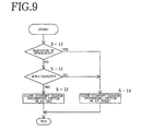
- the output signal of the limiter circuit 20 or a standby charge current command is selected, for example, by changing over the switch by the procedure shown in FIG. 9.
- step S-11 an inquiry is made in step S-11 as to whether the elevator is in operation.
- step S-12 a further inquiry is made in step S-12 as to whether the capacity is below 60%. If the answer is affirmative, step S-13 follows to change over the standby charge prohibiting switch S4 to SET side to select the standby charge current command. If on the other hand the inquiry of step S-11 is answered in the affirmative or the inquiry of step S-12 is answered in the negative, step S-14 follows to change over the switch S4 to RESET side to select the output of the limiter 20. Consequently, the battery is charged to about 60% of the rated capacity when the elevator is at rest.
- a transistor Tr3 interposed between the input terminals a, b of the inverter 3 is turned on to cause a resistor R to consume the regenerative power.
- the mode of handling the limiter value of the limiter circuit 20 shown in FIG. 3 can be altered not only according to the charged state of the battery E described but also according to the operating state of the elevator.
- the proper amount of charge of the battery E is basically set at 60% of the rated capacity, but can be altered for weekdays or holidays or for a particular time zone. For example in the case where a continued power running operation is expected as when people are arriving at office buildings for work, the proper amount of charge of the battery E is set to a somewhat greater value, with preference for use as an auxiliary power source, whereas in the case where a continued regenerative operation is conversely expected as during the lunch time, the amount of charge of the battery E is set at a somewhat smaller value, with preference given to the regenerative operation.
- the discharge-side limiter value may be set at a value which will not greatly alter the charge amount of the battery E, e.g., a value enabling supply of about 30% of the rated power of the motor.
- the power to be supplied from the commercial power source can then be not greater than the remaining 70% even when the elevator is in operation with the rated load thereon. This makes it possible to greatly reduce the capacity of the power source equipment.
- the brake for the motor 1M can be held operable by the power supply from the battery even when a power failure occurs during the operation of the elevator, enabling the elevator to come to a halt at the nearest floor with safety even in the event of a power failure.
- the present embodiment is adapted for use with elevators of the well bucket type, the embodiment is usable also for other elevators, for example, those of the type which carries a battery as a counterweight and wherein the sheave on the counterweight side is driven directly.
- the power source device described needs only to be added to a conventional elevator, whereby regenerative power can be obtained suitably as shown in FIG. 17 to replenish the drive power during the usual operation of the elevator even if the load involves great variations. Accordingly, a great power source equipment need not be pre-set, making it possible to greatly reduce the capacity of the power source equipment.
- the recovery of regenerative power ensures effective use of energy to achieve an improved efficiency.
- the saving of power to be achieved per year can be about 1000 KWh. This value corresponds to about 20% of the total amount of power to be consumed by this elevator.
- the battery comprises nickel-hydrogen cells which are free from harmful substances and are presently considered to be optimal, and is therefore unlikely to entail environmental problems.
- this embodiment has the same construction as the first embodiment, and is further so constructed that the capacity meter is preset or reset by holding the battery charged or discharged under a predetermined condition.
- a state wherein the charge-discharge permitting switch S2 is on and the discharge prohibiting switch S1 is off is changed over to a state wherein the charge-discharge permitting switch S2 is off and the discharge prohibiting switch S1 is on for a predetermined period, for example, every other hour, with the charge prohibiting switch S3 off, and the discharge-side limiter value is set to zero to hold the battery E charged (charging mode).
- the charging mode can be set while the elevator is at rest.
- the battery E is charged up completely until the voltage across the terminals of the battery E becomes sufficiently high, for example, until a voltage is reached at which the battery internally starts to evolve a gas.
- the capacity meter Q is preset at 100%. This eliminates the accumulated error of the meter.
- the capacity meter can be reset by the discharge mode of the battery.
- a state wherein the charge-discharge permitting switch S2 is on and the charge prohibiting switch S3 is off is changed over to a state wherein the charge-discharge permitting switch S2 is off and the charge prohibiting switch S3 is on for a predetermined period, for example, every other hour, with the discharge prohibiting switch S1 off, and the charge-side limiter value is set to zero to hold the battery E discharged (discharging mode).
- the battery E is discharged fully until the voltage across the terminals of the battery E becomes sufficiently low, e.g., until the voltage drops to not higher than about 1/3 of the rated voltage.
- the capacity meter Q is reset to 0%. This eliminates the accumulated error of the meter.
- FIG. 10 shows an example of procedure for presetting the capacity meter by holding the battery charged.
- step S-21 the unit voltages are input, and an inquiry is made in step S-22 as to whether the difference between a maximum value max of the unit voltages and a mininum value min thereof is in excess of a reference voltage 1.
- step S-23 follows to set a reset charge flag, whereby charging of the battery is started.
- step S-24 an inquiry is made in step S-24 as to whether the total sum of the unit voltages is in excess of a reference voltage 2. If the battery is completely charged up, giving an affirmative answer to the inquiry, step S-25 follows to reset the reset charge flag, whereby charging of the battery is completed.
- step S-26 "100%" is stored in the capacity memory of the capacity meter to preset the capacity meter.
- the elevator is operated in the usual manner based on the measurements of the capacity meter, while regenerative power is absorbed suitably and the drive power is replenished, with errors of the capacity meter corrected suitably.
- the power source device of the invention exhibits the advantages thereof to the full extent.
- this embodiment has the same construction as the first embodiment, and is further so constructed that variations in the amounts of charges of the cells constituting the battery are eliminated by holding the battery charged or discharged under a predetermined condition.
- the battery E comprises a plurality of units each comprising eight cells B as shown in FIG. 11.
- the embodiment comprises isolated amplifiers 31 to 31n for detecting voltages V1 to Vn across the terminals of the respective units, an A/D converter 32 for converting output signals from the amplifiers to digital signals, and a microcomputer 33 for on/off controlling the switches S1 to S3 shown in FIG. 4 based on the voltage values V1 to Vn obtained from the A/D converter 32.
- the microcomputer 33 monitors the voltage values V1 to Vn, and changes over a state wherein the charge-discharge permitting switch S2 is on, and the discharge prohibiting switch S1 and the charge prohibiting switch S3 are off (the switches being shown in FIG.
- a discharging mode is set by changing over to a state wherein the charge-discharge permitting switch S2 and the discharge prohibiting switch S1 are off and the charge prohibiting switch S3 are on, and the elevator is held in operation until the terminal voltages of the cells or units become sufficiently low, for example, until the cell voltage drops below about 1/3 of the rated voltage of the cell, to completely discharge each cell and to thereby eliminate the variation in the charge amount of each cell.
- the capacity meter Q is reset at this time as in the second embodiment, the accumulated error of the meter Q can be eliminated.
- the elevator is operated in the usual manner, while regenerative power is absorbed suitably and the drive power is replenished. If variations occurred in the charge amounts of cells or units constituting the battery, the charge amounts can be made uniform, consequently enabling the power source device of the invention to exhibit the advantages thereof to the full extent. The accumulated error of the capacity meter can also be eliminated.
- This embodiment basically has the same construction as the first embodiment and is further so constructed as to judge the life of the battery based on an increase in the internal resistance of the battery.
- the terminal voltage (Va or Vb) of the battery E is fed via an A/D converter 34 to a microcomputer 35, which prepares a life judging signal as shown in FIGS. 12, (a) and (b).
- the signal is fed to the control circuit of the elevator.
- indicated at Ea is the voltage to be produced by the battery E, at Ra the internal resistance of the battery E, and at J a constant-current source for passing a constant current I1 or I2.
- the currents I1 and I2 have the same magnitude but flow in opposite directions.
- the output terminal of the limiter circuit 20 has connected thereto a standby charge prohibiting switch S4 to be changed over for the usual operation or battery life judgement.
- the switch is changed over, the output signal of the limiter circuit 20 is selected for the usual operation, or a standby charge current command I* is selected for passing a constant current through the battery E when the life of the battery E is to be judged.
- the internal resistance Ra of the battery E can be determined by measuring the terminal voltage Va of the battery E during charging and the terminal voltage Vb thereof during discharging. Further a comparison between the internal resistance in the initial state and the internal resistance at present indicates the state of deterioration of the battery E. If the battery E has deteriorated seriously, namely, if the internal resistance of the battery E is in excess of a predetermined value, the battery is replaced by a new one.
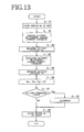
- FIG. 13 shows an example of procedure for judging the life of the battery.
- the standby charge prohibiting switch S4 is changed over to SET side, the battery is charged in response to a standby charge current command in step S-32, and the battery voltage Va is measured in step S-33.
- step S-34 the battery is discharged in response to a standby charge current command, and the battery voltage Vb is then measured in step S-35.
- the internal resistance Ra is thereafter calculated from Mathematical Expression 3 in step S-36.
- An inquiry is made in step S-37 as to whether the internal resistance Ra is in excess of a predetermined value. When the answer is affirmative, an alarm is given in step S-38.
- the switch S4 is closed at RESET side finally in step S-39 to complete the procedure.
- the battery is replaced in response to the alarm. This ensures a high energy efficiency at all times.
- the battery E comprises a plurality of units which are connected in series with one another as shown in FIG. 11, with each of the units comprising eight cells B, the terminal voltage of each unit is checked. This achieves improved accuracy in judging the battery life.
- the life is judged by the above procedure preferably after eliminating the variations in the charge amounts of the cells.
- This embodiment has basically the same construction as the first embodiment and is so constructed as to suppress rush current by a simple circuit.
- contacts 3a connected to the output terminals of the commercial power source 1 are closed to supply power from the converter 2 to the inverter 3, and a capacitor C is charged through a resistor Rb as shown in FIG. 14.
- a contact 2a of a second contact device is closed to short-circuit the resistor Rb to complete preparation for the operation of the elevator.
- an output contact 1a Interposed between an output terminal a of the inverter 3 and the power source circuit 10 is an output contact 1a to be closed when the voltage Vab across the capacitor C is lower than the voltage of the battery E.
- the voltage Vab at the output terminal a of the inverter 3 and the voltage Vdb at a terminal d of the battery E are fed to a comparator 30.
- Vab ⁇ Vdb the comparator delivers a high signal, which closes the output contact 1a of the power source device 10.
- FIG. 15 shows an arrangement wherein the capacitor C is charged in advance through a resistor Ra which is connected in parallel to the output contact 1a, and the output contact 1a is then closed, whereby the rush current can also be suppressed.
Landscapes
- Engineering & Computer Science (AREA)
- Power Engineering (AREA)
- Automation & Control Theory (AREA)
- Business, Economics & Management (AREA)
- Emergency Management (AREA)
- Elevator Control (AREA)
- Charge And Discharge Circuits For Batteries Or The Like (AREA)
Applications Claiming Priority (11)
| Application Number | Priority Date | Filing Date | Title |
|---|---|---|---|
| JP32642199 | 1999-11-17 | ||
| JP32642199A JP4463912B2 (ja) | 1999-11-17 | 1999-11-17 | 交流エレベータの電源装置 |
| JP32832399 | 1999-11-18 | ||
| JP32832399A JP4503746B2 (ja) | 1999-11-18 | 1999-11-18 | 交流エレベータの電源装置 |
| JP35361099 | 1999-12-13 | ||
| JP35361099A JP4503749B2 (ja) | 1999-12-13 | 1999-12-13 | 交流エレベータの電源装置 |
| JP36671999 | 1999-12-24 | ||
| JP36671999A JP4503750B2 (ja) | 1999-12-24 | 1999-12-24 | 交流エレベータの電源装置 |
| JP2000004430 | 2000-01-13 | ||
| JP2000044330 | 2000-01-13 | ||
| PCT/JP2000/008061 WO2001037396A1 (fr) | 1999-11-17 | 2000-11-15 | Alimentation pour ascenseur a ca |
Publications (2)
| Publication Number | Publication Date |
|---|---|
| EP1235323A1 true EP1235323A1 (fr) | 2002-08-28 |
| EP1235323A4 EP1235323A4 (fr) | 2008-08-06 |
Family
ID=27531150
Family Applications (1)
| Application Number | Title | Priority Date | Filing Date |
|---|---|---|---|
| EP00976270A Withdrawn EP1235323A4 (fr) | 1999-11-17 | 2000-11-15 | Alimentation pour ascenseur a ca |
Country Status (9)
| Country | Link |
|---|---|
| US (1) | US6732838B1 (fr) |
| EP (1) | EP1235323A4 (fr) |
| KR (1) | KR100738167B1 (fr) |
| CN (1) | CN100407545C (fr) |
| AU (1) | AU1413001A (fr) |
| CA (1) | CA2391616C (fr) |
| HK (1) | HK1048895A1 (fr) |
| TW (1) | TWI241978B (fr) |
| WO (1) | WO2001037396A1 (fr) |
Cited By (8)
| Publication number | Priority date | Publication date | Assignee | Title |
|---|---|---|---|---|
| WO2005101610A3 (fr) * | 2004-04-16 | 2006-03-30 | Energy Solutions Ni Ltd | Systeme d'alimentation electrique |
| WO2008135626A1 (fr) | 2007-05-02 | 2008-11-13 | Kone Corporation | Appareil d'alimentation d'un système de transport |
| WO2009004644A3 (fr) * | 2007-05-12 | 2009-03-05 | Bharat Shastri | Ascenseur amélioré à des fins de production de puissance |
| ITBO20080427A1 (it) * | 2008-07-07 | 2010-01-08 | Sele S R L | Gruppo di alimentazione per ascensori, elevatori, montacarichi e simili. |
| CN102497160A (zh) * | 2011-11-29 | 2012-06-13 | 东元总合科技(杭州)有限公司 | 电机驱动器交流输入电压幅值估计方法 |
| US8292038B2 (en) | 2007-12-05 | 2012-10-23 | Otis Elevator Company | Control device for operating two elevator cars in a single hoistway |
| US10343872B2 (en) | 2013-05-08 | 2019-07-09 | Otis Elevator Company | Elevator system having battery and energy storage device |
| EP3356274B1 (fr) | 2015-09-30 | 2023-05-31 | Acorn Mobility Services Limited | Système et procédé de montée |
Families Citing this family (48)
| Publication number | Priority date | Publication date | Assignee | Title |
|---|---|---|---|---|
| WO2002081352A1 (fr) * | 2001-04-04 | 2002-10-17 | Toshiba Elevator Kabushiki Kaisha | Dispositif de commande pour treuil |
| CN1213938C (zh) * | 2001-10-17 | 2005-08-10 | 三菱电机株式会社 | 电梯控制装置 |
| KR100874571B1 (ko) * | 2003-10-07 | 2008-12-16 | 오티스 엘리베이터 컴파니 | 전기 엘리베이터 구조 시스템 |
| JP3974899B2 (ja) * | 2004-01-14 | 2007-09-12 | ファナック株式会社 | コンバータ装置、及びコンバータ装置を備えるインバータ装置 |
| US7246686B2 (en) * | 2004-01-30 | 2007-07-24 | Thyssen Elevator Capital Corp. | Power supply for elevator systems having variable speed drives |
| US7165654B2 (en) * | 2004-02-06 | 2007-01-23 | Paceco Corp | Energy storage method for load hoisting machinery |
| US7148652B2 (en) * | 2004-04-30 | 2006-12-12 | Ace-Tronics Company, Inc. | Method and apparatus for determining and handling brake failures in open loop variable frequency drive motors |
| JP4081101B2 (ja) * | 2005-03-28 | 2008-04-23 | 富士通株式会社 | 電力供給装置および電力供給方法 |
| WO2007044000A1 (fr) * | 2005-10-07 | 2007-04-19 | Otis Elevator Company | Systeme electrique pour ascenseur |
| BRPI0520698A2 (pt) * | 2005-11-23 | 2009-09-29 | Otis Elevator Comapany | sistema e método para acionar continuamente um motor de içamento para um elevador a partir de uma fonte de alimentação irregular e sistema para controlar um acionamento regenerativo |
| US7554278B2 (en) * | 2006-06-13 | 2009-06-30 | Railpower Technologies Corp. | Load-lifting apparatus and method of storing energy for the same |
| WO2007145628A1 (fr) * | 2006-06-15 | 2007-12-21 | Otis Elevator Company | Système de stockage d'énergie électrique pour ENTRAÎNer une charge |
| JP4831527B2 (ja) * | 2006-06-28 | 2011-12-07 | 株式会社安川電機 | 電圧形インバータ装置およびその運転方法 |
| EP2117983B1 (fr) * | 2007-02-13 | 2018-09-19 | Otis Elevator Company | Operation de sauvetage automatique pour systeme d'entrainement regenerateur |
| FI120759B (fi) * | 2007-06-20 | 2010-02-15 | Kone Corp | Kuljetusjärjestelmän tehonohjaus |
| FI120426B (fi) * | 2007-09-19 | 2009-10-15 | Kone Corp | Hissin väliaikainen pääkytkinjärjestely |
| CN101149197B (zh) * | 2007-10-26 | 2012-12-05 | 青岛澳柯玛股份有限公司 | 变频制冷系统能量再生控制装置 |
| CA2714974C (fr) * | 2008-02-21 | 2016-07-19 | J.S. Redpath Limited | Systeme mecanise de griffe de montage alimente par batterie |
| RU2484003C2 (ru) * | 2008-07-25 | 2013-06-10 | Отис Элевэйтор Компани | Способ эксплуатации лифта в аварийном режиме |
| JP2012508880A (ja) * | 2008-11-17 | 2012-04-12 | オーチス エレベータ カンパニー | バッテリ充電状態較正 |
| ES2571939T3 (es) * | 2008-11-21 | 2016-05-27 | Otis Elevator Co | Operación de un accionamiento regenerativo trifásico a partir de fuentes de alimentación de corriente continua CC y corriente alterna CA monofásica mezcladas |
| FI122048B (fi) * | 2009-06-01 | 2011-07-29 | Kone Corp | Kuljetusjärjestelmä |
| US20110061976A1 (en) * | 2009-09-17 | 2011-03-17 | Tiner James L | Battery counterweighted elevator |
| EP2598425B1 (fr) | 2010-07-30 | 2020-02-26 | Otis Elevator Company | Commande régénératrice d'entraînement d'ascenseur référencée à un bus cc |
| JP2012040206A (ja) * | 2010-08-19 | 2012-03-01 | Toshiba Corp | 医用画像診断装置及び天板移動ユニット |
| CN102381594B (zh) * | 2010-08-31 | 2014-02-26 | 上海三菱电梯有限公司 | 电梯节能装置 |
| US8884561B2 (en) * | 2010-09-06 | 2014-11-11 | Mitsubishi Electric Corporation | AC motor driving apparatus |
| JP5335855B2 (ja) * | 2011-05-27 | 2013-11-06 | 株式会社日立製作所 | エレベーター駆動システム |
| CN102225730A (zh) * | 2011-06-24 | 2011-10-26 | 上海应用技术学院 | 自动扶梯节能控制的共直流母线变频传动系统 |
| JP5839873B2 (ja) * | 2011-07-19 | 2016-01-06 | 東芝エレベータ株式会社 | ハイブリッド駆動型エレベータの制御装置 |
| CN103874649B (zh) * | 2011-10-18 | 2015-09-30 | 三菱电机株式会社 | 电梯的再生蓄电控制装置 |
| EP2888810A4 (fr) * | 2012-08-21 | 2017-02-08 | John Michael Moltion | Système de production d'énergie électrique |
| JP6196764B2 (ja) * | 2012-10-09 | 2017-09-13 | 三菱重工業株式会社 | 電力供給装置、電力供給方法およびプログラム |
| JP5602890B2 (ja) * | 2013-01-29 | 2014-10-08 | ファナック株式会社 | 蓄電装置および抵抗放電装置を有するモータ制御装置 |
| EP2956395B1 (fr) * | 2013-02-14 | 2020-04-01 | Otis Elevator Company | Commande de vitesse de cabine d'ascenseur dans un système d'ascenseur alimenté par batterie |
| CN103350935A (zh) * | 2013-07-17 | 2013-10-16 | 湖南中建建科机械有限公司 | 节能控制系统 |
| CN103368206B (zh) * | 2013-07-17 | 2016-01-27 | 湖南中建建科机械有限公司 | 整流回馈电路 |
| KR101329366B1 (ko) * | 2013-08-21 | 2013-11-14 | 이옥형 | 회생 에너지 저장 기능을 갖는 엘리베이터 제어 장치 |
| EP3049360A4 (fr) * | 2013-09-24 | 2017-05-24 | Otis Elevator Company | Système d'ascenseur utilisant un dispositif d'emmagasinage de secours pour puissance accrue |
| CN104578848B (zh) * | 2015-01-28 | 2018-03-30 | 哈尔滨工业大学 | 一种基于自动能耗匹配的超高速发电机整流器 |
| JP6331228B2 (ja) * | 2016-02-10 | 2018-05-30 | 株式会社安川電機 | モータ制御装置、電力変換装置、補助電源装置、及び補助電源制御方法 |
| DK3290375T3 (da) * | 2016-08-29 | 2019-09-30 | Kone Corp | Elevator |
| US10604378B2 (en) | 2017-06-14 | 2020-03-31 | Otis Elevator Company | Emergency elevator power management |
| EP3447016B1 (fr) * | 2017-08-24 | 2023-12-06 | KONE Corporation | Système de puissance pour le transport dans le sens vertical, un procédé et des agencements de transport vertical |
| US11053096B2 (en) | 2017-08-28 | 2021-07-06 | Otis Elevator Company | Automatic rescue and charging system for elevator drive |
| JP6593716B2 (ja) * | 2017-11-10 | 2019-10-23 | 株式会社安川電機 | モータ制御装置、電力変換装置、補助電源装置、及び補助電源制御方法 |
| CN112242807A (zh) * | 2020-09-02 | 2021-01-19 | 深圳通业科技股份有限公司 | 电机驱动控制电路及电机驱动控制方法 |
| CN118100331A (zh) * | 2022-11-25 | 2024-05-28 | 台达电子企业管理(上海)有限公司 | 电能转换系统及其辅助供电方法 |
Family Cites Families (37)
| Publication number | Priority date | Publication date | Assignee | Title |
|---|---|---|---|---|
| US4316097A (en) * | 1979-12-14 | 1982-02-16 | Reynolds William R | Backup power circuit |
| JPS5836867A (ja) * | 1981-08-25 | 1983-03-03 | 三菱電機株式会社 | 交流エレベ−タの非常時運転装置 |
| JPS58183578A (ja) * | 1982-04-20 | 1983-10-26 | 三菱電機株式会社 | 交流エレベ−タの制御装置 |
| US4456097A (en) * | 1982-10-12 | 1984-06-26 | Otis Elevator Company | Elevator battery charging control |
| JPS59149781A (ja) * | 1983-02-16 | 1984-08-27 | Mitsubishi Electric Corp | エレベ−タの制御装置 |
| JPS59203072A (ja) * | 1983-05-04 | 1984-11-17 | 三菱電機株式会社 | 交流エレベ−タの制御装置 |
| JPS59207375A (ja) * | 1983-05-10 | 1984-11-24 | 三菱電機株式会社 | エレベ−タの制御装置 |
| US4489812A (en) * | 1983-07-22 | 1984-12-25 | Ferris Loren B | Power recovery system and method for elevator apparatus |
| JPS6043094A (ja) * | 1983-08-17 | 1985-03-07 | Mitsubishi Electric Corp | エレベ−タの故障時運転装置 |
| JPS60191979A (ja) * | 1984-03-11 | 1985-09-30 | 三菱電機株式会社 | エレベ−タ用電動機制御装置 |
| JPS61248881A (ja) * | 1985-04-22 | 1986-11-06 | 三菱電機株式会社 | エレベ−タの制御装置 |
| JPS61267675A (ja) | 1985-05-20 | 1986-11-27 | 株式会社東芝 | エレベ−タの制御装置 |
| FI81465C (fi) | 1986-12-22 | 1990-10-10 | Kone Oy | Anordning foer kopplandet av ett ackumulatorbatteri till en hissinverters likstroemskrets. |
| JPH0710150B2 (ja) * | 1987-09-03 | 1995-02-01 | 富士電機株式会社 | 電流可逆チヨッパの運転方法 |
| US5058710A (en) * | 1990-08-14 | 1991-10-22 | Otis Elevator Company | Elevator power source device |
| JPH04153176A (ja) * | 1990-10-16 | 1992-05-26 | Mitsubishi Electric Corp | エレベータの監視・制御装置 |
| JP2656684B2 (ja) * | 1991-06-12 | 1997-09-24 | 三菱電機株式会社 | エレベータの停電時運転装置 |
| US5341902A (en) * | 1993-03-08 | 1994-08-30 | Ruiz Sr Rene A | Energy saver elevator |
| JP3314789B2 (ja) * | 1993-06-18 | 2002-08-12 | 富士電機株式会社 | インバータ駆動装置 |
| JP3136926B2 (ja) * | 1994-11-08 | 2001-02-19 | 松下電器産業株式会社 | 蓄電池の状態管理システム |
| FI99109C (fi) * | 1994-11-29 | 1997-10-10 | Kone Oy | Varavoimajärjestelmä |
| JP3261901B2 (ja) * | 1994-12-19 | 2002-03-04 | 三菱電機株式会社 | エレベーターの非常時運転装置 |
| JP3487952B2 (ja) * | 1995-04-14 | 2004-01-19 | 株式会社日立製作所 | 電気自動車の駆動装置及び駆動制御方法 |
| JP3177405B2 (ja) * | 1995-05-31 | 2001-06-18 | 三洋電機株式会社 | 二次電池の充放電制御方法及び装置 |
| JPH0921851A (ja) * | 1995-07-04 | 1997-01-21 | Hitachi Building Syst Eng & Service Co Ltd | エレベータ非常電源装置用バッテリの残存容量測定装置 |
| KR19990034240A (ko) * | 1997-10-28 | 1999-05-15 | 류정열 | 전기자동차의 배터리 충방전제어시스템 |
| JP3594283B2 (ja) * | 1998-01-09 | 2004-11-24 | 東芝エレベータ株式会社 | エレベータの停電時救出運転装置 |
| JPH11299275A (ja) | 1998-04-14 | 1999-10-29 | Osaka Gas Co Ltd | エレベータの電源装置 |
| KR100312771B1 (ko) * | 1998-12-15 | 2002-05-09 | 장병우 | 엘리베이터의정전운전제어장치및방법 |
| JP2000255918A (ja) * | 1999-03-04 | 2000-09-19 | Mitsubishi Electric Corp | エレベータ装置及びエレベータシステム |
| US6196355B1 (en) * | 1999-03-26 | 2001-03-06 | Otis Elevator Company | Elevator rescue system |
| JP2001187677A (ja) * | 1999-12-28 | 2001-07-10 | Mitsubishi Electric Corp | エレベータの制御装置 |
| JP4409692B2 (ja) * | 1999-12-28 | 2010-02-03 | 三菱電機株式会社 | エレベータの制御装置 |
| JP4261010B2 (ja) * | 2000-02-28 | 2009-04-30 | 三菱電機株式会社 | エレベータの制御装置 |
| JP4347982B2 (ja) * | 2000-02-28 | 2009-10-21 | 三菱電機株式会社 | エレベーターの制御装置 |
| JP4343381B2 (ja) * | 2000-02-28 | 2009-10-14 | 三菱電機株式会社 | エレベーターの制御装置 |
| JP2001240325A (ja) * | 2000-02-28 | 2001-09-04 | Mitsubishi Electric Corp | エレベータの制御装置 |
-
2000
- 2000-11-15 CN CN008184755A patent/CN100407545C/zh not_active Expired - Fee Related
- 2000-11-15 HK HK03100995.2A patent/HK1048895A1/en unknown
- 2000-11-15 US US10/129,131 patent/US6732838B1/en not_active Expired - Lifetime
- 2000-11-15 EP EP00976270A patent/EP1235323A4/fr not_active Withdrawn
- 2000-11-15 AU AU14130/01A patent/AU1413001A/en not_active Abandoned
- 2000-11-15 WO PCT/JP2000/008061 patent/WO2001037396A1/fr not_active Ceased
- 2000-11-15 CA CA002391616A patent/CA2391616C/fr not_active Expired - Fee Related
- 2000-11-15 KR KR1020027006280A patent/KR100738167B1/ko not_active Expired - Fee Related
- 2000-11-16 TW TW089124232A patent/TWI241978B/zh not_active IP Right Cessation
Non-Patent Citations (2)
| Title |
|---|
| No further relevant documents disclosed * |
| See also references of WO0137396A1 * |
Cited By (12)
| Publication number | Priority date | Publication date | Assignee | Title |
|---|---|---|---|---|
| WO2005101610A3 (fr) * | 2004-04-16 | 2006-03-30 | Energy Solutions Ni Ltd | Systeme d'alimentation electrique |
| WO2008135626A1 (fr) | 2007-05-02 | 2008-11-13 | Kone Corporation | Appareil d'alimentation d'un système de transport |
| US8217617B2 (en) | 2007-05-02 | 2012-07-10 | Kone Corporation | Power supply appliance of a transport system |
| EP2142459A4 (fr) * | 2007-05-02 | 2013-10-16 | Kone Corp | Appareil d'alimentation d'un système de transport |
| WO2009004644A3 (fr) * | 2007-05-12 | 2009-03-05 | Bharat Shastri | Ascenseur amélioré à des fins de production de puissance |
| US8292038B2 (en) | 2007-12-05 | 2012-10-23 | Otis Elevator Company | Control device for operating two elevator cars in a single hoistway |
| ITBO20080427A1 (it) * | 2008-07-07 | 2010-01-08 | Sele S R L | Gruppo di alimentazione per ascensori, elevatori, montacarichi e simili. |
| CN102497160A (zh) * | 2011-11-29 | 2012-06-13 | 东元总合科技(杭州)有限公司 | 电机驱动器交流输入电压幅值估计方法 |
| CN102497160B (zh) * | 2011-11-29 | 2014-03-26 | 东元总合科技(杭州)有限公司 | 电机驱动器交流输入电压幅值估计方法 |
| US10343872B2 (en) | 2013-05-08 | 2019-07-09 | Otis Elevator Company | Elevator system having battery and energy storage device |
| EP2994973B1 (fr) * | 2013-05-08 | 2020-03-25 | Otis Elevator Company | Batterie d'accumulateurs chargée par énergie hybride ou topologies d'attaque alimentées par supercondensateurs |
| EP3356274B1 (fr) | 2015-09-30 | 2023-05-31 | Acorn Mobility Services Limited | Système et procédé de montée |
Also Published As
| Publication number | Publication date |
|---|---|
| US6732838B1 (en) | 2004-05-11 |
| AU1413001A (en) | 2001-05-30 |
| CA2391616C (fr) | 2007-04-03 |
| KR100738167B1 (ko) | 2007-07-10 |
| EP1235323A4 (fr) | 2008-08-06 |
| HK1048895A1 (en) | 2003-04-17 |
| CN100407545C (zh) | 2008-07-30 |
| CN1425214A (zh) | 2003-06-18 |
| WO2001037396A1 (fr) | 2001-05-25 |
| TWI241978B (en) | 2005-10-21 |
| KR20020082204A (ko) | 2002-10-30 |
| CA2391616A1 (fr) | 2001-05-25 |
Similar Documents
| Publication | Publication Date | Title |
|---|---|---|
| CA2391616C (fr) | Dispositif d'alimentation pour ascenseur a ca | |
| JP4452399B2 (ja) | 交流エレベータの電源装置 | |
| KR100407630B1 (ko) | 엘리베이터의 제어장치 | |
| KR100407628B1 (ko) | 엘리베이터의 제어장치 | |
| RU2495813C2 (ru) | Управление мощностью от нескольких источников в системе питания лифта | |
| KR100415747B1 (ko) | 엘리베이터의 제어장치 | |
| US6435313B2 (en) | Controller for dynamically allocating regenerative power to a rechargeable power supply of an elevator | |
| KR100509146B1 (ko) | 엘리베이터의 제어장치 | |
| JP6445190B2 (ja) | 電池制御装置 | |
| JP4302847B2 (ja) | エレベータの制御装置 | |
| JP6236391B2 (ja) | 電力用電池に対する充電量を平衡させるための装置 | |
| RU2493090C2 (ru) | Управление общим током и аккумулированием энергии в приводе лифта | |
| JPH11299275A (ja) | エレベータの電源装置 | |
| JP5457332B2 (ja) | 電源装置、機械式駐車装置、及び電源装置の制御方法 | |
| SG191508A1 (en) | Drive apparatus of elevator apparatus | |
| JP4679756B2 (ja) | エレベータの制御装置 | |
| JP2005089134A (ja) | エレベータの制御装置 | |
| JPH08186940A (ja) | 組電池充電制御回路 |
Legal Events
| Date | Code | Title | Description |
|---|---|---|---|
| PUAI | Public reference made under article 153(3) epc to a published international application that has entered the european phase |
Free format text: ORIGINAL CODE: 0009012 |
|
| 17P | Request for examination filed |
Effective date: 20020617 |
|
| AK | Designated contracting states |
Kind code of ref document: A1 Designated state(s): AT BE CH CY DE DK ES FI FR GB GR IE IT LI LU MC NL PT SE |
|
| AX | Request for extension of the european patent |
Free format text: AL;LT;LV;MK;RO;SI |
|
| RAP1 | Party data changed (applicant data changed or rights of an application transferred) |
Owner name: FUJITEC CO., LTD |
|
| RBV | Designated contracting states (corrected) |
Designated state(s): AT BE DE GB |
|
| A4 | Supplementary search report drawn up and despatched |
Effective date: 20080704 |
|
| 17Q | First examination report despatched |
Effective date: 20081001 |
|
| STAA | Information on the status of an ep patent application or granted ep patent |
Free format text: STATUS: THE APPLICATION HAS BEEN WITHDRAWN |
|
| 18W | Application withdrawn |
Effective date: 20130222 |
|
| REG | Reference to a national code |
Ref country code: HK Ref legal event code: WD Ref document number: 1048895 Country of ref document: HK |