EP1236670A1 - Fin de course de sécurité pour ascenseur - Google Patents
Fin de course de sécurité pour ascenseur Download PDFInfo
- Publication number
- EP1236670A1 EP1236670A1 EP01104968A EP01104968A EP1236670A1 EP 1236670 A1 EP1236670 A1 EP 1236670A1 EP 01104968 A EP01104968 A EP 01104968A EP 01104968 A EP01104968 A EP 01104968A EP 1236670 A1 EP1236670 A1 EP 1236670A1
- Authority
- EP
- European Patent Office
- Prior art keywords
- buffer
- limit switch
- car
- elevator
- emergency limit
- Prior art date
- Legal status (The legal status is an assumption and is not a legal conclusion. Google has not performed a legal analysis and makes no representation as to the accuracy of the status listed.)
- Granted
Links
- 239000000872 buffer Substances 0.000 claims abstract description 95
- 238000013459 approach Methods 0.000 description 4
- 238000010276 construction Methods 0.000 description 2
- 241001441724 Tetraodontidae Species 0.000 description 1
- 230000002349 favourable effect Effects 0.000 description 1
- 239000011888 foil Substances 0.000 description 1
- 230000003993 interaction Effects 0.000 description 1
Images


Classifications
-
- B—PERFORMING OPERATIONS; TRANSPORTING
- B66—HOISTING; LIFTING; HAULING
- B66B—ELEVATORS; ESCALATORS OR MOVING WALKWAYS
- B66B5/00—Applications of checking, fault-correcting, or safety devices in elevators
- B66B5/28—Buffer-stops for cars, cages, or skips
- B66B5/284—Buffer-stops for cars, cages, or skips mounted on cars or counterweights
Definitions
- the invention relates to an elevator for transporting Loads and / or persons with the characteristics of the generic term of claim 1.
- the emergency limit switch is usually on the side of one Guide rail of the car held and includes one Gearshift lever with one mounted on the car Switching curve interacts.
- the car falls below a specified minimum distance to the allocated buffer, so the further movement of the car Shift lever pivoted by means of the shift curve in such a way that the emergency limit switch supplies the power to the drive motor off.
- Such a construction has the disadvantage that the shift lever and the associated Switching curve are aligned exactly to each other need to ensure that the emergency limit switch is reliable is operated.
- the orientation of the pivot lever The switching curve must be at regular intervals be checked.
- Another disadvantage arises from that the switching curve to reach a switching point by pivoting the shift lever relatively large minimum travel path of the car required.
- the elevator shaft is below or if necessary above the respective final stop of the car a not inconsiderable route must provide so that the shaft pit or Shaft head of the elevator shaft an additional depth must have.
- the object of the present invention is an elevator of the type mentioned in such a way that the assembly of the emergency limit switch simplified and the Depth of the pit and the shaft head reduced can be.
- the buffer can be at the top and / or bottom of the Elevator shaft and the associated buffer area can be arranged on the car and / or on the counterweight his. However, it can also be an inverted arrangement be provided such that the buffer on the car and / or on the counterweight and the buffer contact area arranged at the upper and / or lower end of the elevator shaft is.
- the emergency limit switch can be made contactless through the buffer or the buffer impact area assigned to the buffer operated, for example in the form of a proximity switch, especially a magnetic field sensor, which is less than a minimum distance between Car or counterweight on the one hand and buffer on the other detected and then an electrical control signal provides.
- the emergency limit switch is mechanical, for example can be actuated by pressurization. You can do this in particular pressure-sensitive switching elements for Use, with the help of mechanical contact between buffer and assigned buffer contact area can be detected.
- the emergency limit switch is held on the buffer and can be actuated by the buffer contact surface. It is advantageous if the emergency limit switch cannot be moved is fixed to the buffer and by the Buffer allocated, on the car and / or on the counterweight arranged buffer contact surface is actuated. It is favorable if the emergency limit switch can already be actuated is before the buffer strikes the buffer contacted.
- the emergency limit switch can be next to the buffer or with a correspondingly high buffer version also in be arranged in the buffer.
- the emergency limit switch is assigned to the buffer contact area for example on the car and / or on the counterweight held and actuated by the buffer.
- the buffer has a button trains through which an actuator of Emergency limit switch can be actuated.
- the buffer contact area is on a stop is arranged on the car and / or is positioned on the counterweight or in the elevator shaft.
- the emergency limit switch can advantageously on or in the stop can be arranged.
- the buffer assigned to the car Stop is held, the buffer contact area trains, and if at the stop the emergency limit switch is arranged.
- the assembly of the emergency limit switch can thus together with the assembly of the stop respectively.
- the emergency limit switch is over the buffer contact area in the direction of the buffer protruding actuator, for example a Has switching plunger.
- the stop is preferably plate-shaped, the emergency limit switch facing away from the buffer Rear of the stop is arranged and that Actuator a through opening of the stop reaches through and protrudes towards the buffer.
- FIGs 1 to 4 is a schematic representation an elevator with the reference number 10 as a whole shown with two running along an elevator shaft 12 Guide rails 14, 15 on which a car 16 by means of guide elements 22, 23 and one known and therefore not shown in the drawing Drive, for example an electric drive, is kept movable.
- the shaft pit 18 in this area designed with a horizontally running shaft floor 19 and vertically aligned shaft walls 20.
- the buffer 25 has a stop on the car 16 in the form assigned a stop plate 26 which on its Buffer 25 facing the front of a buffer contact area 28 trains. If the car 16 has a in the drawing, not shown final stop move towards the shaft floor 19, see above hits the buffer contact surface 28 on the car 16 facing end face 30 of the buffer 25, the deformed with further movement of the car 16 and the Movement of the car 16 stops.
- an emergency limit switch 34 arranged with whose help is the power supply of the electric drive can be interrupted.
- the emergency limit switch 34 includes an actuator in the form of a spring-loaded Switch plunger 36, the through hole 38 of the stop plate 26 reaches through and over the buffer contact area 28 protrudes towards the buffer 25.
- the emergency limit switch 34 is in the in Figures 1 to 4 shown embodiment held on the car 16 and is actuated by the fixed buffer 25.
- the switching plunger 36 over the end face 30 in the direction of the car 16 survive.
- the buffer contact surface 28 Switch plunger so that the emergency limit switch is actuated mechanically becomes.
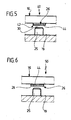
- FIG 5 is a section of the lower end region a further advantageous embodiment in the form of a Elevator 40 shown, with the exception of the for Coming emergency limit switch is constructed as the elevator 10, so that the same for identical components Reference numerals were used as in Figures 1 to 4.
- the elevator 40 also includes a car 16, that on its underside facing the shaft floor 19 a stop plate 26 assigned to the buffer 25 wearing. While in the illustrated in Figures 1 to 4 Elevator 10 is a mechanical emergency limit switch 34 is used with a switching plunger 36, the 5 shows an emergency limit switch 42 with an actuator in the form of a pressure sensitive Switching foil 44. The latter covers the Buffer 25 facing buffer contact surface 28 of the stop plate 26 and occurs when the car hits 16 on the buffer 25 with the latter in mechanical interaction, being due to the pressure load occurring the switching film 44 actuated and thereby a power supply of the drive used becomes.
- the lower end region is another alternative Shown in the form of an elevator 50, the same reference numerals for identical components used as in Figure 5.
- the elevator 50 differs from the elevator explained above 40 only in that the switching film 44 is not on the buffer contact surface 28 of the stop plate 26 is arranged, but between the stop plate 26 and the car 16.
- the switching film 44 is by the Buffer 25 actuated by the buffer 25 over the stop plate 26 a pressure load on the back arranged switching film 44 is exercised.
Landscapes
- Cage And Drive Apparatuses For Elevators (AREA)
- Push-Button Switches (AREA)
- Keying Circuit Devices (AREA)
- Maintenance And Inspection Apparatuses For Elevators (AREA)
- Types And Forms Of Lifts (AREA)
Priority Applications (4)
| Application Number | Priority Date | Filing Date | Title |
|---|---|---|---|
| DE50114598T DE50114598D1 (de) | 2001-03-01 | 2001-03-01 | Notendschalter für Aufzug |
| AT01104968T ATE418520T1 (de) | 2001-03-01 | 2001-03-01 | Notendschalter für aufzug |
| ES01104968T ES2317860T3 (es) | 2001-03-01 | 2001-03-01 | Elevador. |
| EP01104968A EP1236670B1 (fr) | 2001-03-01 | 2001-03-01 | Fin de course de sécurité pour ascenseur |
Applications Claiming Priority (1)
| Application Number | Priority Date | Filing Date | Title |
|---|---|---|---|
| EP01104968A EP1236670B1 (fr) | 2001-03-01 | 2001-03-01 | Fin de course de sécurité pour ascenseur |
Publications (2)
| Publication Number | Publication Date |
|---|---|
| EP1236670A1 true EP1236670A1 (fr) | 2002-09-04 |
| EP1236670B1 EP1236670B1 (fr) | 2008-12-24 |
Family
ID=8176634
Family Applications (1)
| Application Number | Title | Priority Date | Filing Date |
|---|---|---|---|
| EP01104968A Expired - Lifetime EP1236670B1 (fr) | 2001-03-01 | 2001-03-01 | Fin de course de sécurité pour ascenseur |
Country Status (4)
| Country | Link |
|---|---|
| EP (1) | EP1236670B1 (fr) |
| AT (1) | ATE418520T1 (fr) |
| DE (1) | DE50114598D1 (fr) |
| ES (1) | ES2317860T3 (fr) |
Cited By (2)
| Publication number | Priority date | Publication date | Assignee | Title |
|---|---|---|---|---|
| CN101958196A (zh) * | 2010-09-17 | 2011-01-26 | 中国北方车辆研究所 | 一种行程限位装置 |
| WO2017029533A1 (fr) * | 2015-08-17 | 2017-02-23 | Otis Elevator Company | Système d'amortisseur d'ascenseur |
Citations (5)
| Publication number | Priority date | Publication date | Assignee | Title |
|---|---|---|---|---|
| JPH0318578A (ja) * | 1989-06-13 | 1991-01-28 | Mitsubishi Electric Corp | エレベータ用緩衝装置 |
| JPH06278963A (ja) * | 1993-03-26 | 1994-10-04 | Mitsubishi Electric Corp | エレベーター装置 |
| EP0663367A1 (fr) * | 1993-04-05 | 1995-07-19 | Kone Oy | Structure d'amortisseur |
| WO1999047447A1 (fr) * | 1998-03-18 | 1999-09-23 | Kone Corporation | Dispositif de securite pour ascenseur |
| EP1052212A1 (fr) * | 1999-05-14 | 2000-11-15 | Inventio Ag | Equipement pour effectuer des travaux dans une cage d'ascenseur |
-
2001
- 2001-03-01 AT AT01104968T patent/ATE418520T1/de active
- 2001-03-01 EP EP01104968A patent/EP1236670B1/fr not_active Expired - Lifetime
- 2001-03-01 DE DE50114598T patent/DE50114598D1/de not_active Expired - Lifetime
- 2001-03-01 ES ES01104968T patent/ES2317860T3/es not_active Expired - Lifetime
Patent Citations (5)
| Publication number | Priority date | Publication date | Assignee | Title |
|---|---|---|---|---|
| JPH0318578A (ja) * | 1989-06-13 | 1991-01-28 | Mitsubishi Electric Corp | エレベータ用緩衝装置 |
| JPH06278963A (ja) * | 1993-03-26 | 1994-10-04 | Mitsubishi Electric Corp | エレベーター装置 |
| EP0663367A1 (fr) * | 1993-04-05 | 1995-07-19 | Kone Oy | Structure d'amortisseur |
| WO1999047447A1 (fr) * | 1998-03-18 | 1999-09-23 | Kone Corporation | Dispositif de securite pour ascenseur |
| EP1052212A1 (fr) * | 1999-05-14 | 2000-11-15 | Inventio Ag | Equipement pour effectuer des travaux dans une cage d'ascenseur |
Non-Patent Citations (2)
| Title |
|---|
| PATENT ABSTRACTS OF JAPAN vol. 015, no. 138 (M - 1100) 8 April 1991 (1991-04-08) * |
| PATENT ABSTRACTS OF JAPAN vol. 1995, no. 01 28 February 1995 (1995-02-28) * |
Cited By (5)
| Publication number | Priority date | Publication date | Assignee | Title |
|---|---|---|---|---|
| CN101958196A (zh) * | 2010-09-17 | 2011-01-26 | 中国北方车辆研究所 | 一种行程限位装置 |
| CN101958196B (zh) * | 2010-09-17 | 2013-08-21 | 中国北方车辆研究所 | 一种行程限位装置 |
| WO2017029533A1 (fr) * | 2015-08-17 | 2017-02-23 | Otis Elevator Company | Système d'amortisseur d'ascenseur |
| CN107922155A (zh) * | 2015-08-17 | 2018-04-17 | 奥的斯电梯公司 | 电梯缓冲系统 |
| CN107922155B (zh) * | 2015-08-17 | 2019-12-17 | 奥的斯电梯公司 | 电梯缓冲系统 |
Also Published As
| Publication number | Publication date |
|---|---|
| EP1236670B1 (fr) | 2008-12-24 |
| DE50114598D1 (de) | 2009-02-05 |
| ATE418520T1 (de) | 2009-01-15 |
| ES2317860T3 (es) | 2009-05-01 |
Similar Documents
| Publication | Publication Date | Title |
|---|---|---|
| DE69026216T2 (de) | Fangvorrichtung | |
| EP0743031A2 (fr) | Glissière pour tiroir | |
| DE102013006414A1 (de) | Vorrichtung zur Bedienung mehrerer Funktionen in einem Kraftfahrzeug | |
| DE60300664T2 (de) | Vorrichtung zur Montage einer Beleuchtungseinheit an Elementen des Aufbaus eines Kraftfahrzeugs | |
| EP2802526B1 (fr) | Dispositif de guidage pour un moyen de réception de charge, associé de manière télescopique | |
| DE3013835C2 (fr) | ||
| DE3148855C2 (de) | Druck- oder Schiebetastenschalter | |
| DE3138686C2 (fr) | ||
| EP1236670A1 (fr) | Fin de course de sécurité pour ascenseur | |
| EP3391400B1 (fr) | Commutateur électrique | |
| DE102021110000A1 (de) | Drucktastenbaugruppe | |
| DE19953204A1 (de) | Schaltmodul zum Schalten von Steuerstrombahnen, insbesondere in Fahrzeugen | |
| EP0794498A2 (fr) | Lecteur de cartes codées | |
| DE3411597C2 (de) | Schiebeschalter | |
| EP3771609B1 (fr) | Tampon plongeur pourvu de poussoir enrobé par de section | |
| DE102004028058A1 (de) | Elektronische Einrichtung | |
| EP2050706B1 (fr) | Dispositif de fixation | |
| EP0401544A2 (fr) | Touche pour un clavier | |
| DE9113293U1 (de) | Tastatur mit verschnappten Gehäusehälften | |
| CH672758A5 (fr) | ||
| DE8421271U1 (de) | Fuehrungsschuh fuer einen fahrkrob von aufzuegen | |
| DE19861324B4 (de) | Schutzabdeckung zum Abschirmen von Gleitführungen an Werkzeugmaschinen | |
| DE9005303U1 (de) | Hub-Drehtisch-Vorrichtung | |
| EP0278894A1 (fr) | Interverrouillage mécanique pour interrupteurs électriques | |
| DE1931792A1 (de) | Verriegelung fuer Umsetzer von Stapelgeraeten |
Legal Events
| Date | Code | Title | Description |
|---|---|---|---|
| PUAI | Public reference made under article 153(3) epc to a published international application that has entered the european phase |
Free format text: ORIGINAL CODE: 0009012 |
|
| 17P | Request for examination filed |
Effective date: 20011206 |
|
| AK | Designated contracting states |
Kind code of ref document: A1 Designated state(s): AT BE CH CY DE DK ES FI FR GB GR IE IT LI LU MC NL PT SE TR |
|
| AX | Request for extension of the european patent |
Free format text: AL;LT;LV;MK;RO;SI |
|
| RAP1 | Party data changed (applicant data changed or rights of an application transferred) |
Owner name: THYSSENKRUPP AUFZUGSWERKE GMBH |
|
| AKX | Designation fees paid |
Designated state(s): AT CH DE ES FR GB LI |
|
| 17Q | First examination report despatched |
Effective date: 20061211 |
|
| GRAP | Despatch of communication of intention to grant a patent |
Free format text: ORIGINAL CODE: EPIDOSNIGR1 |
|
| GRAS | Grant fee paid |
Free format text: ORIGINAL CODE: EPIDOSNIGR3 |
|
| GRAA | (expected) grant |
Free format text: ORIGINAL CODE: 0009210 |
|
| AK | Designated contracting states |
Kind code of ref document: B1 Designated state(s): AT CH DE ES FR GB LI |
|
| REG | Reference to a national code |
Ref country code: GB Ref legal event code: FG4D Free format text: NOT ENGLISH |
|
| REG | Reference to a national code |
Ref country code: CH Ref legal event code: NV Representative=s name: ISLER & PEDRAZZINI AG Ref country code: CH Ref legal event code: EP |
|
| REF | Corresponds to: |
Ref document number: 50114598 Country of ref document: DE Date of ref document: 20090205 Kind code of ref document: P |
|
| REG | Reference to a national code |
Ref country code: ES Ref legal event code: FG2A Ref document number: 2317860 Country of ref document: ES Kind code of ref document: T3 |
|
| PLBE | No opposition filed within time limit |
Free format text: ORIGINAL CODE: 0009261 |
|
| STAA | Information on the status of an ep patent application or granted ep patent |
Free format text: STATUS: NO OPPOSITION FILED WITHIN TIME LIMIT |
|
| 26N | No opposition filed |
Effective date: 20090925 |
|
| REG | Reference to a national code |
Ref country code: DE Ref legal event code: R082 Ref document number: 50114598 Country of ref document: DE Representative=s name: HOEGER, STELLRECHT & PARTNER PATENTANWAELTE MB, DE |
|
| REG | Reference to a national code |
Ref country code: FR Ref legal event code: PLFP Year of fee payment: 16 |
|
| PGFP | Annual fee paid to national office [announced via postgrant information from national office to epo] |
Ref country code: AT Payment date: 20160322 Year of fee payment: 16 Ref country code: FR Payment date: 20160321 Year of fee payment: 16 |
|
| PGFP | Annual fee paid to national office [announced via postgrant information from national office to epo] |
Ref country code: DE Payment date: 20170322 Year of fee payment: 17 Ref country code: CH Payment date: 20170322 Year of fee payment: 17 |
|
| PGFP | Annual fee paid to national office [announced via postgrant information from national office to epo] |
Ref country code: GB Payment date: 20170322 Year of fee payment: 17 |
|
| PGFP | Annual fee paid to national office [announced via postgrant information from national office to epo] |
Ref country code: ES Payment date: 20170315 Year of fee payment: 17 |
|
| REG | Reference to a national code |
Ref country code: AT Ref legal event code: MM01 Ref document number: 418520 Country of ref document: AT Kind code of ref document: T Effective date: 20170301 |
|
| REG | Reference to a national code |
Ref country code: FR Ref legal event code: ST Effective date: 20171130 |
|
| PG25 | Lapsed in a contracting state [announced via postgrant information from national office to epo] |
Ref country code: FR Free format text: LAPSE BECAUSE OF NON-PAYMENT OF DUE FEES Effective date: 20170331 Ref country code: AT Free format text: LAPSE BECAUSE OF NON-PAYMENT OF DUE FEES Effective date: 20170301 |
|
| REG | Reference to a national code |
Ref country code: DE Ref legal event code: R119 Ref document number: 50114598 Country of ref document: DE |
|
| REG | Reference to a national code |
Ref country code: CH Ref legal event code: PL |
|
| GBPC | Gb: european patent ceased through non-payment of renewal fee |
Effective date: 20180301 |
|
| PG25 | Lapsed in a contracting state [announced via postgrant information from national office to epo] |
Ref country code: DE Free format text: LAPSE BECAUSE OF NON-PAYMENT OF DUE FEES Effective date: 20181002 |
|
| PG25 | Lapsed in a contracting state [announced via postgrant information from national office to epo] |
Ref country code: CH Free format text: LAPSE BECAUSE OF NON-PAYMENT OF DUE FEES Effective date: 20180331 Ref country code: LI Free format text: LAPSE BECAUSE OF NON-PAYMENT OF DUE FEES Effective date: 20180331 Ref country code: GB Free format text: LAPSE BECAUSE OF NON-PAYMENT OF DUE FEES Effective date: 20180301 |
|
| REG | Reference to a national code |
Ref country code: ES Ref legal event code: FD2A Effective date: 20190801 |
|
| PG25 | Lapsed in a contracting state [announced via postgrant information from national office to epo] |
Ref country code: ES Free format text: LAPSE BECAUSE OF NON-PAYMENT OF DUE FEES Effective date: 20180302 |