EP1238562B1 - Procede, systeme, convertisseur et commutateur pour communication a mode de transfert asynchrone (atm) - Google Patents
Procede, systeme, convertisseur et commutateur pour communication a mode de transfert asynchrone (atm) Download PDFInfo
- Publication number
- EP1238562B1 EP1238562B1 EP00977451A EP00977451A EP1238562B1 EP 1238562 B1 EP1238562 B1 EP 1238562B1 EP 00977451 A EP00977451 A EP 00977451A EP 00977451 A EP00977451 A EP 00977451A EP 1238562 B1 EP1238562 B1 EP 1238562B1
- Authority
- EP
- European Patent Office
- Prior art keywords
- traffic
- contract
- end station
- signalling message
- requested
- Prior art date
- Legal status (The legal status is an assumption and is not a legal conclusion. Google has not performed a legal analysis and makes no representation as to the accuracy of the status listed.)
- Expired - Lifetime
Links
- 238000000034 method Methods 0.000 title claims abstract description 28
- 238000004891 communication Methods 0.000 title claims abstract description 26
- 230000011664 signaling Effects 0.000 claims abstract description 112
- 238000006243 chemical reaction Methods 0.000 claims abstract description 23
- 230000005540 biological transmission Effects 0.000 claims abstract description 9
- 238000012545 processing Methods 0.000 claims abstract description 7
- 230000002349 favourable effect Effects 0.000 claims description 9
- 238000003780 insertion Methods 0.000 claims description 3
- 230000037431 insertion Effects 0.000 claims description 3
- 239000000872 buffer Substances 0.000 description 9
- 238000010586 diagram Methods 0.000 description 9
- 230000006727 cell loss Effects 0.000 description 4
- 230000006978 adaptation Effects 0.000 description 3
- 238000012546 transfer Methods 0.000 description 3
- 230000002457 bidirectional effect Effects 0.000 description 1
- 238000001514 detection method Methods 0.000 description 1
- 238000011161 development Methods 0.000 description 1
- 230000007704 transition Effects 0.000 description 1
Images




Classifications
-
- H—ELECTRICITY
- H04—ELECTRIC COMMUNICATION TECHNIQUE
- H04L—TRANSMISSION OF DIGITAL INFORMATION, e.g. TELEGRAPHIC COMMUNICATION
- H04L49/00—Packet switching elements
- H04L49/30—Peripheral units, e.g. input or output ports
- H04L49/3081—ATM peripheral units, e.g. policing, insertion or extraction
-
- H—ELECTRICITY
- H04—ELECTRIC COMMUNICATION TECHNIQUE
- H04Q—SELECTING
- H04Q11/00—Selecting arrangements for multiplex systems
- H04Q11/04—Selecting arrangements for multiplex systems for time-division multiplexing
- H04Q11/0428—Integrated services digital network, i.e. systems for transmission of different types of digitised signals, e.g. speech, data, telecentral, television signals
- H04Q11/0478—Provisions for broadband connections
-
- H—ELECTRICITY
- H04—ELECTRIC COMMUNICATION TECHNIQUE
- H04L—TRANSMISSION OF DIGITAL INFORMATION, e.g. TELEGRAPHIC COMMUNICATION
- H04L12/00—Data switching networks
- H04L12/54—Store-and-forward switching systems
- H04L12/56—Packet switching systems
- H04L12/5601—Transfer mode dependent, e.g. ATM
- H04L2012/5619—Network Node Interface, e.g. tandem connections, transit switching
-
- H—ELECTRICITY
- H04—ELECTRIC COMMUNICATION TECHNIQUE
- H04L—TRANSMISSION OF DIGITAL INFORMATION, e.g. TELEGRAPHIC COMMUNICATION
- H04L12/00—Data switching networks
- H04L12/54—Store-and-forward switching systems
- H04L12/56—Packet switching systems
- H04L12/5601—Transfer mode dependent, e.g. ATM
- H04L2012/5629—Admission control
- H04L2012/563—Signalling, e.g. protocols, reference model
-
- H—ELECTRICITY
- H04—ELECTRIC COMMUNICATION TECHNIQUE
- H04L—TRANSMISSION OF DIGITAL INFORMATION, e.g. TELEGRAPHIC COMMUNICATION
- H04L12/00—Data switching networks
- H04L12/54—Store-and-forward switching systems
- H04L12/56—Packet switching systems
- H04L12/5601—Transfer mode dependent, e.g. ATM
- H04L2012/5672—Multiplexing, e.g. coding, scrambling
Definitions
- the invention relates to a method according to the preamble of claim 1.
- FIG.-1 in which a system, wherein the method is applied, is schematically shown.
- FIG. 1 shows an example of a communication system which operates in the asynchronous transmission mode (ATM).
- the system includes two switches or switching devices 11 and 12 which are connected to one another and to end stations 13 and 14, respectively.
- the switches 11 and 12 may be equal and the end stations 13 and 14 may be equal.
- the switches 11 and 12 may be connected to more switches and end stations. This is indicated by double arrows, such as 15, which depart from the switches.
- the system is suitable for setting up a connection or communication between the end stations 13 and 14, by way of a link 16, the switch 11, a link 17, the switch 12 and a link 18, respectively.
- An ATM communication system is suitable for the transmission of digital data from various services, such as television, telephony and various Internet services. That is why the end stations 13 and 14, presented as computers in FIG. 1 and in other figures, serve only as an example.
- An ATM packet is called a cell, and has a fixed length of 53 octets, 48 of which are intended for data and 5 for a header containing checking and routing information.
- the information of the header of a cell comprises:
- a first kind of cell contains information which is used for signalling, particularly for setting up a requested connection according to a desired diagram or kind of contract for traffic-flow handling. Such cells are designated below as information cells.
- Another type of cell contains the data proper which is being exchanged from one end station to another end station. Such cells are designated below as data cells.
- FIG. 2 schematically shows an information cell 20 whose header contains an ST (Signalling Type) indication.
- FIG. 3 schematically shows a data cell 21 whose header contains an RT (Routing Type) indication, which implies for which end station the data of the cell is intended.
- RT Recording Type
- the end station 13 When the end station 13, as the source end station, requests the setup of a connection having the end station 14 as destination end station, the end station 13, over the virtual circuit of the link 16, transmits a series of information cells 20 to the switch 11.
- the switch 11 distinguishes the information cells from other types of cells and combines the data of the information cells 20. This is shown in FIG. 4.
- the data of a series of information cells 20 fcrms a signalling message 24 consisting of several information elements IE1, ..., IEn.
- the information elements contain, inter alia, information on an ATM kind of traffic contract or ATC ( A TM T ransfer C apability), consisting of several components, including a Traffic Descriptor IE, which in its turn consists of a set of traffic parameters describing the properties of the kind of traffic handling requested, by the source end station 13 or a switch 11, from a next switch 12 of the connection or the destination end station 14.
- ATC ATM kind of traffic contract
- ATC A TM T ransfer C apability
- Traffic Descriptor IE which in its turn consists of a set of traffic parameters describing the properties of the kind of traffic handling requested, by the source end station 13 or a switch 11, from a next switch 12 of the connection or the destination end station 14.
- a switch 11, 12 therefore comprises, for each kind of contract, a buffer for storing cells received from various source end stations 13 and other switches and for, depending on the amount of traffic, reading from the buffer, in accordance with the kind of contract, and transmitting the cells to a next switch or a destination end station.
- Such a hardware implementation is expensive, the switch for each kind of contract having to possess such a buffer and associated control means.
- an ATM-network manager may only offer the limited number of associated contracts to users of the end stations 13, 14.
- the end stations 13, 14 request a traffic handling according to the UBR kind of contract and the switches support, apart from possible other kinds of contract, the UBR kind of contract.
- the setup of the connection halts and the source end station 13 will not be capable of communicating with the destination end station 14. Since the two end stations 13, 14 may be connected to one another by way of a series of ATM networks, each having a number of switches of different owners and managers, chances are that one of the switches of the desired connection does not support a kind of contract requested from the switch, and the requested connection with the destination end station cannot be set up.
- the object of the invention is to remove the drawbacks of the known method.
- the invention provides a method as described in claim 1.
- the ATM infrastructure is better utilised, which may lead to an earlier expansion thereof for a greater processing capacity for traffic according to existing kinds of traffic contract and/or for enlargement of the number of supported kinds of traffic contract.
- the invention further relates to a system, a converter and a switch for communication in the asynchronous transmission mode (ATM) according to claims 11, 12 and 13, respectively.
- ATM asynchronous transmission mode
- the ATM communication system according to the invention shown in FIG. 5 comprises a switch 11 and end stations 13, 14 as of the system of FIG. 1. Between the end station 13 and the switch 11, a converter 30 was mounted.
- the switch 11 supports one or more different kinds of contract.
- the switch 11 does not support a kind of contract supported and requested by the end station 13 (in the example: UBR), but does support another kind of contract, which is not more unfavourable than the kind of contract requested by the source end station, then the converter 30 converts the kind of contract requested by the end station 13 into the other kind of contract (in the example: SBR).
- a converter 31 was mounted between the switch 11 and the end station 14, a converter 31 was mounted.
- the converter 31 fulfils the same function, for the end station 14 with respect to the switch 11, as the converter 30 fulfils for the end station 13 with respect to switch 11. Since the end stations 13, 14 generally request the same kind of traffic contract for traffic handling, the converters 30, 31 will differ since the converter 31 carries out a reverse conversion (in the example: from SBR into UBR).
- the converters 30 and 31 may be part of a public ATM communication system of one or more networks, each having one or more switches, such as the switch 11.
- the converters 30 and 31 may also be part of a private ATM communication network having end stations 13 and 14, respectively. Although some links may be physically short, in FIG. 5, viewed from end station 13 in the direction of end station 14, the links 34, 35, 36, 37 may be distinguished.
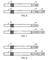
- FIG. 6, 7 and 8 schematically show examples of signalling messages of the kind explained in combination with FIG. 4, which are transmitted according to three different methods over the links 34 to 37 inclusive of the system of FIG. 5.
- both end stations 13 and 14 apply a traffic handling according to the UBR kind of contract.
- IEs having specific functions are included in respective, predetermined locations of signalling messages
- ATC IEs are distinguished from other IEs by means of a label L, which may be a number. Only for the sake of convenience, in FIG. 6 to 8 inclusive the ATC IEs are shown at an end of the signalling messages.
- the signalling message 40 whose ATC IE 41 contains a label L1 (meaning: the IE contains an indication for a requested kind of contract) and an indication of the UBR kind of contract, is transmitted over the link 34.
- the converter 30 modifies the signalling message 40 into a signalling message 42, which is transmitted over the link 35.
- the signalling message 42 contains the ATC IE 41 of the signalling message 40 and an ATC IE 43, added by the converter 30, which again contains the label L1 and an indication for the SBR kind of contract supported by the switch 11.
- the label L1 therefore has a significance which depends on the number of IEs having the label L1 which contains the signalling message 40, 42, i.e., the IE having the label L1 contains an indication for a kind of contract which was, or will be, requested prior to or after the conversion, as the case may be. Since ATC IEs 41 and 43 both have the same label L1, their locations with respect to one another are of importance for the switch 11 in the signalling message 42. This is why said locations must comply with a rule to be drawn up for that purpose.
- the same signalling message 42 is transmitted as over the link 35. Since the converter 31 carries out a reverse conversion of the kinds of contract (from SBR into UBR), over the link 37 the same signalling message 40 is transmitted as over the link 34.
- the converter 30 converts the signalling message 40 transmitted over the link 34 into a signalling message 44 whose ATC IE 45 contains a label L2 (meaning: the IE contains an indication for the kind of contract which was requested prior to the conversion) and the kind of contract information UBR of the ATC IE 41.
- a second ATC IE 46 of the signalling message 44 contains the label L1 (meaning: the IE contains an indication for the kind of contract to which there has been converted) of the ATC IE 41 and the kind of contract information SBR of the kind of contract supported by the switch 11.
- the signalling message When, departing from the source end station 13, there would have been converted into two or more other kinds of contract, the signalling message will contain more ATC IEs 46 and their locations in the signalling message 44 will be of importance.
- the converter 31 converts the signalling message 44 back into the signalling message 40.
- An ATM communication network between two end stations may comprise a number of ATM networks, each having one or more switches, it being possible that the various switches support various kinds of contract or various groups of kinds of contract. Since furthermore a signalling message between an end station and the remainder of the system differs from a signalling message between two nodes or switches of the system, it may be desirable to distinguish the ATC IEs associated with the interface or the link between an end station and a converter or switch connected thereto from ATC IEs associated with interfaces between switches and converters.
- FIG. 8 shows an example of a method in which this is the case. According to FIG.
- the converter 30 converts the signalling message 47 into a signalling message 49 which consists of the signalling message 47 plus an ATC IE 50 which contains a label L4 (meaning: the IE contains an indication of a kind of contract applied between switches and converters) reserved for interfaces between switches 11, 12 and converters 30, 31 and a kind of contract associated with said interface, e.g., SBR.
- the converters 30 en 31 of the system of FIG. 5 are associated with private ATM systems, in order to distinguish between private and public domains, over the links 34 and 37, instead of the signalling message 40, the signalling message 47 might be transmitted.
- FIG. 9 shows a diagram of an independent converter of a kind of contract.
- the converter 52 shown in FIG. 9 is suitable for bidirectional data transmission.
- the converter 52 includes multiplexers 53, 54 for connection to links, such as the links 34, 35 of FIG. 5, respectively.
- the multiplexer 53 For a traffic flow received by the multiplexer 53 from outside the converter 52, the multiplexer 53 separates information cells 20, as of FIG. 2, from the remainder of the traffic flow. The information cells 20 are delivered to an information-cell processor 55. The remainder of the traffic flow received by the multiplexer 53 is delivered to a multiplexer 56.
- the multiplexer 56 delivers a traffic flow received from the multiplexer 53 to a multiplexer 57, which delivers it, by way of the multiplexer 54, to the link 35.
- the multiplexer 56 When the traffic source connected to the link 34 does not support the requested kind of traffic contract, but another kind of contract which is not more unfavourable than the kind of contract requested by the source end station 13, is supported by the traffic destination, the multiplexer 56, under control of the information-cell processor 55, delivers a traffic flow received from the multiplexer 53 to a traffic-adapting means 58.
- the traffic-adapting means 58 adapts the traffic flow received by it, under control of the information-cell processor 55, to the other kind of traffic contract, and delivers the adapted traffic flow, by way of the multiplexers 57 and 54, to the link 35.
- a traffic-adapting means 59 fulfils the same function for a traffic flow received by the multiplexer 54 from the link 35, by adapting it to the kind of contract supported on the side of the link 34.
- the information-cell processor 55 receives the information cells 20 from the multiplexer 53 or 54, joins the information from said information cells 20 to form a complete signalling message 24, and determines the presence therein of information elements IE1 to IEn inclusive, as illustrated in FIG. 4. Based on one or more of the information elements IE, the information-cell processor 55 determines whether the incoming traffic flow must be adapted for further transport according to another kind of contract or not. When no adaptation is required, the processor 55 controls the multiplexers 56 and 57 to deliver the traffic flow received by any of said multiplexers unaltered to the other of said multiplexers. In the other case, the processor 55 controls the multiplexers 56, 57 and the traffic-adapting means 58 for adapting the traffic flow to the kind of contract supported on the output side 35 of the converter 52.
- Multiplexer 54 for a traffic flow coming from the link 35 and intended for the link 34, is identical to the multiplexer 53 and delivers information cells separated from said traffic flow to the information-cell processor 55 and delivers the remainder of the traffic flow to the multiplexer 57, which is identical to the multiplexer 56.
- FIG. 10 shows a diagram of an embodiment of a traffic-adapting means, such as the adapting means 58 of FIG. 9.
- the adapting means 58 includes a data buffer 61 and, connected to the buffer 61, a maximum-level control 62, an output-dosage temporiser 63 and a cell-header-piece adapter 64.
- the traffic-adapting means 58 When the traffic-adapting means 58 must carry out an adaptation of the traffic flow, it receives data cells 21 from the multiplexer 56, which are explained in combination with FIG. 3.
- the kind of contract on the side of the link 34 is UBR
- the kind of contract on the side of the link 35 is SBR.
- the UBR kind of contract permits data cells which, within a time unit, are received in excess of a predetermined number, to be ignored.
- the SBR kind of contract does not have this restriction.
- the control 62 By means of the control 62, the maximum is determined, up to which the data buffer 61 accepts data cells delivered thereto.
- the temporiser 63 determines, with which rate data cells are delivered from the buffer 61 to the cell-header-piece adapting means 64.
- more groups, consisting of a data buffer 61, a maximum-level control 62 and an output-dosage temporiser 63 may be mounted and the information-cell processor 55 may set the controls 62 and temporisers 63. If so required, the cell-header-piece adapting means 64, under control of the processor 55, adapts the header of the cells, e.g., the value of the cell-loss-priority bit CLP.
- FIG. 11 shows a diagram of functional parts of which the information-cell processor 55 may consist.
- the information-cell processor 55 includes a signalling-message interpreter 71 and, connected thereto, a multiplex control 72 and a signalling-message converter 73.
- the signalling-message interpreter 71 is connected to the multiplexers 53 and 54 for receiving therefrom, or delivering thereto, information cells 20 of the associated signalling message 24.
- the interpreter 71 controls the multiplexers 56, 57 and the traffic-adapting means 58, 59 for adapting the received traffic flow, or not.
- the interpreter 71 When the interpreter 71 has determined that a conversion must be carried out, the interpreter controls the signalling-message converter 73 for adapting the signalling message, as explained in combination with FIG. 6 to 8 inclusive in such a way, that a receiver of the adapted signalling message is capable of determining that a conversion has taken place for, in accordance therewith, adapting back the traffic flow and converting back the signalling message, or not.
- the converter 52 of FIG. 9 will have so many pairs of traffic-adapting means 58, 59 as there are required simultaneous adaptations of the kind of contract. Even if the converter 52 need only adapt between two kinds of contracts, the application of a converter 52 requires a relatively large investment, since the converter 52 must be applied for each connection and an ATM switch in general is connected to a large number of links for a large number of connections.
- FIG. 12 shows a diagram of an ATM switch 80 which is suitable for connecting to an number of links, such as 16 and 17 of FIG. 1, but which in FIG. 12 are each indicated by number 81 and which are connected to an ATM switching unit 83 of the switch 80.
- the switch 80 further comprises, connected to the switching unit 83, an information-cell processor 55 and traffic-adapting means 58, 59.
- the information-cell processor 55 and the traffic-adapting means 58, 59 of FIG. 12 are functionally identical to the processor 55 and the adapting means 58, 59 cf FIG. 9, and there may be several groups, consisting of an information-cell processor 55 and traffic-adapting means 58, 59, connected to the ATM switching unit 83.
- said groups are to be assigned to a connection for which a conversion is to be carried out.
- a switch in accordance with FIG. 12 a considerable saving may be achieved on equipment.
- programs and tables, particularly routing tables, in a computer of a switch in the event of programmatic implementation of the switch 80 of FIG. 12, too, there may be achieved a considerable saving.
- FIG. 13 shows a second example of an ATM communication system to which the invention is applied.
- the system includes a number of switches 84, 85, 86, 87.
- the switches 84 and 87 are switches of a private ATM network to which the respective end stations 13 and 14 are connected.
- the switches 85 and 86 are switches of, e.g., two coupled public ATM networks. It is assumed that, as indicated next to it, the end stations 13 and 14 support the UBR kind of contract. It is further assumed that the switch 85 is suitable for handling traffic according to the SBR kind of contract and that the switch 86 is capable of handling traffic according to the DBR kind of contract, as indicated next to the switches.
- a converter 91 is mounted between the switch 84 and the switch 85, and a converter 92 is mounted between the switch 85 and the switch 86, at least one converter, e.g., the converters 93 and 94, being mounted between the switch 86 and the switch 87.
- the converters 91 to 94 inclusive may be mounted in various locations with respect to the switches connected thereto, the converter 91 is part of, e.g., the private network having the switch 84, the converters 92 and 93 are part of the same public network, and the converter 94 is part of a private network having the switch 87.
- the converters 91, 92, 93, 94 carry out a conversion from UBR to the more favourable SBR, from SBR to the more favourable DBR, from DBR to SBR and from SBR to UBR, respectively.
- the various signalling messages over the connection between the end stations 13 and 14 may be completed, in the way explained in combination with figures 6, 7 and 8, by each of the converters 91 to 94 inclusive, with an information element IE on a kind of traffic contract, and stripped of such a completed IE.
- Figures 14 and 15 show two alternative methods for completing signalling messages by traffic-contract-kind IEs, and for stripping or adapting them, which may be particularly suitable when, over the connection between the end stations 13 and 14, a large number of conversions are carried out, various networks of various operators having to be passed, and groups of one or more switches, e.g., the switch 86, having a converter 92, 93 on either side, being desired to be kept transparent for the traffic flow.
- switches e.g., the switch 86, having a converter 92, 93 on either side, being desired to be kept transparent for the traffic flow.
- the source end station 13 of FIG. 13 delivers information cells from a signalling message 47 as explained in combination with FIG. 8.
- the contract-kind information element, ATC IE 48 of the signalling message 47 comprises a label L3 which is reserved for use by end stations, such as 13 and 14.
- the ATC IE 48 contains an indication of the kind of contract requested by the source end station, UBR in this example.
- the converter 91 converts the signalling message 47 into a signalling message 95 which comprises the ATC IE 48 of the signalling message 47, completed by an ATC IE 96.
- the IE 96 contains a label L5 which is reserved for traffic between network nodes or switches, and which indicates that the IE 96 represents a stack of the kind "last in, first out” (LIFO) containing indications of kinds of contract into which conversion has taken place, and in so far as required for carrying out a reverse conversion.
- the converter 91 completes the stack ATC IE 96 by an indication of the SBR kind of contract.
- the converter 92 modifies the signalling message 95 into a signalling message 97 by the ATC IE 48 and an ATC IE 98 whose label L5 indicates that it contains a stack of contract-kind indications, in this instance SBR and DBR.
- the converter 93 carries out a reverse conversion of the DBR kind of contract into the SBR kind of contract, in such a manner that a signalling message between the converters 93 and 94 has the form of the signalling message 95 of FIG. 14.
- the converter 94 carries out a reverse conversion of the SBR kind of contract into the UBR kind of contract, in such a manner that a signalling message between the converter 94 and the source end station 14 has the form of the signalling message 47 of FIG. 14.
- the method according to FIG. 15 differs from the method according to FIG. 14, since the signalling messages 47, 95, 97 are replaced by a signalling message 101 having an ATC IE 102, a signalling message 103 having an ATC IE 104, and a signalling message 105 having an ATC IE 106, respectively.
- the signalling messages 101, 103 and 105 contain only one ATC IE whose label L6 indicates that the ATC IE contains a stack of the kind "last in, first out" (LIFO) of contract-kind indications.
- the signalling message 101 contains the UBR indication
- the signalling message 103 contains the UBR and SBR indications
- the signalling message 105 contains the UBR, SBR and DBR indications. Since the signalling messages in the example of FIG. 15 contain only a single ATC IE, and therefore a single label L6, the signalling messages 101, 103, 105 may be shorter than the other signalling messages explained above.
- the connection of the source end station 13 to the destination end station 14 passes switches or converters which support kinds of traffic contract which enable an earlier reverse conversion to a less favourable kind of traffic contract etc., even into the kind of traffic contract requested by the source end station 13.
- the switch 86 of FIG. 13 in addition to DBR, also supports UBR, the converter 92 may be made suitable to convert from SBR into UBR in such a manner that the switch 86 and the converters 93 and 94 can be transparent or absent for the traffic flow according to the UBR kind of contract delivered by the converter 92.
- the converter 93 might directly convert DBR into UBR, as a result of which the converter 94 may be transparent or absent.
- the signalling message contains an indication, over all links in one or two traffic-contract-kind IEs, of the kind of traffic contract requested by the source end station 13, and possibly an indication of another kind of traffic contract into which there was most recently converted and which is the valid requested kind of traffic contract.
- the kind of signalling messages 40, 42, 44, 47, 49, 95, 101, 103 shown in figures 6-8, 14 and 15 may be used.
Landscapes
- Engineering & Computer Science (AREA)
- Computer Networks & Wireless Communication (AREA)
- Signal Processing (AREA)
- Data Exchanges In Wide-Area Networks (AREA)
- Supply And Distribution Of Alternating Current (AREA)
- Filters And Equalizers (AREA)
- Telephonic Communication Services (AREA)
Claims (13)
- Procédé de communication pour transmettre des cellules d'information numériques (20) et des cellules de données (21) dans un mode transmission asynchrone (ATM) dans un système de communication ATM comprenant deux stations d'extrémité ou plus (13, 14) et un ou plusieurs commutateurs (11, 84-87), une station d'extrémité de source (13) et une station d'extrémité de destination (14) des stations d'extrémité (13, 14) étant connectées l'une à l'autre au moyen de liaisons (16-18, 34-37) via un ou plusieurs des commutateurs, la station d'extrémité de source (13) et chaque commutateur permettant d'instaurer une connexion entre la station d'extrémité de source (13) et la station d'extrémité de destination (14), démarrant au niveau de la station d'extrémité de source (13), délivrant un message de signalisation (24) à un commutateur suivant ou à la station d'extrémité de destination (14), selon le cas, le message de signalisation (24) étant formé par plusieurs cellules d'information (20), le message de signalisation (24) comprenant plusieurs éléments d'information (IE), un élément d'information de type de contrat de trafic (IE) contenant une indication qui indique un type de contrat de trafic (ATC) qui est demandé en requête depuis un commutateur suivant ou depuis la station d'extrémité de destination (14), chaque commutateur traitant, conformément à une indication qui est reçue par le commutateur, un flux de trafic qui suit le message de signalisation et qui est constitué par des cellules de données, et un type de contrat de trafic qui est demandé en requête par la station d'extrémité de source (13) et un type de contrat de trafic qui est demandé en requête depuis la station d'extrémité de destination (14) étant le seul et même type de contrat de trafic de station d'extrémité,
caractérisé en ce que, lorsqu'un commutateur ou la station d'extrémité de destination ne supporte pas un type de contrat de trafic qui est demandé en requête depuis mais supporte de fait un autre type de contrat de trafic qui n'est pas moins favorable que le type de contrat de trafic de station d'extrémité, le message de signalisation, avant sa délivrance sur le commutateur ou sur la station d'extrémité de destination depuis lequel ou laquelle le type de contrat de trafic est demandé en requête, est converti :pour autant que l'indication n'est pas encore présente dans le message de signalisation, en additionnant, au message de signalisation, une indication qui désigne l'autre type de contrat de trafic en tant que type de contrat qui est demandé en requête ; etlorsque le message de signalisation contient une indication qui désigne l'autre type de contrat de trafic mais pas en tant que type de contrat de trafic qui est demandé en requête, en enlevant du message de signalisation l'indication pour le type de contrat de trafic précédant immédiatement la conversion. - Procédé selon la revendication 1, caractérisé en ce que le nombre d'indications pour des types de contrat de trafic demandés en requête de façon consécutive depuis des commutateurs et depuis la station d'extrémité de destination dans le message de signalisation (40, 42, 44, 47, 49, 95, 101, 103) n'excède pas le nombre deux, dont un type est une indication pour le type de contrat de trafic de station d'extrémité.
- Procédé selon la revendication 1, caractérisé en ce que, pour enlever des indications du type de contrat de trafic pendant des conversions consécutives, une séquence pour enlever les indications est appliquée, laquelle séquence est l'inverse d'une séquence à l'aide de laquelle les indications ont été additionnées précédemment au message de signalisation.
- Procédé selon la revendication 1, caractérisé en ce que la conversion est mise en oeuvre au moyen d'une conversion selon un type le moins favorable de contrat de trafic, qui n'est pas moins favorable que le type de contrat de trafic de station d'extrémité.
- Procédé selon la revendication 1, caractérisé en ce que, lorsque, au niveau d'un côté d'entrée d'un commutateur ou d'un certain nombre de commutateurs consécutifs supportant le même type de contrat de trafic, une conversion a été mise en oeuvre, au niveau du côté de sortie du commutateur ou d'un dernier du nombre de commutateurs, selon le cas, une conversion inverse est mise en oeuvre pour les mêmes types de contrat de trafic tel que pendant la conversion précédente.
- Procédé selon la revendication 1, caractérisé en ce qu'un ordre d'indications (41, 43, 45, 48) des types valides de contrat de trafic et de ceux demandés en requête plus tôt est déterminé dans le message de signalisation (40, 42, 44, 47, 49) au moyen d'une séquence temporelle à l'aide de laquelle les indications sont additionnées au message de signalisation.
- Procédé selon la revendication 1, caractérisé en ce que des étiquettes sont assignées à des éléments d'information, qui contiennent des indications du type de contrat de trafic, une étiquette de l'élément d'information comportant l'indication pour le type de contrat de trafic demandé en requête valide différant des autres étiquettes, qui sont égales, et dont l'ordre des éléments d'information associés est déterminé dans le message de signalisation au moyen de la séquence temporelle à l'aide de laquelle les indications sont additionnées au message de signalisation.
- Procédé selon la revendication 1, caractérisé en ce que des étiquettes sont assignées à des éléments d'information qui contiennent des indications du type de contrat de trafic, l'étiquette de l'élément d'information comportant l'indication pour le type de contrat de station d'extrémité différant des autres étiquettes, qui sont égales, et dont l'ordre des éléments d'information associés est déterminé dans le message de signalisation au moyen de la séquence temporelle à l'aide de laquelle les indications sont additionnées au message de signalisation.
- Procédé selon la revendication 1, caractérisé en ce que des indications qui sont additionnées au message de signalisation (47, 95, 97) sont ordonnées selon un unique élément d'information (96, 98) et en ce qu'un ordre des indications est déterminé, dans l'unique élément d'information, au moyen de la séquence temporelle à l'aide de laquelle les indications sont additionnées.
- Procédé selon la revendication 1, caractérisé en ce que toutes les indications du message de signalisation (101, 103, 105) sont ordonnées selon un unique élément d'information (102, 104, 106) et un en ce qu'ordre des indications est déterminé, dans l'unique élément d'information, au moyen de la séquence temporelle à l'aide de laquelle les indications sont additionnées.
- Système de communication pour transmettre, dans le mode de transmission asynchrone (ATM), des cellules d'information numériques (20) et des cellules de données (21), comprenant deux stations d'extrémité ou plus (13, 14) et un ou plusieurs commutateurs (11, 84-87), une station d'extrémité de source (13) et une station d'extrémité de destination (14) des stations d'extrémité (13, 14) étant connectées l'une à l'autre au moyen de liaisons (16-18, 34-37) via un ou plusieurs des commutateurs, la station d'extrémité de source (13) et chaque commutateur permettant d'instaurer une connexion entre la station d'extrémité de source (13) et la station d'extrémité de destination (14), démarrant au niveau de la station d'extrémité de source (13), délivrant un message de signalisation (24) à un commutateur suivant ou à la station d'extrémité de destination (14), selon le cas, le message de signalisation (24) étant formé par plusieurs cellules d'information (20), le message de signalisation (24) comprenant plusieurs éléments d'information (IE), un élément d'information de type de contrat de trafic (IE) contenant une indication qui indique un type de contrat de trafic (ATC) qui est demandé en requête depuis un commutateur suivant ou depuis la station d'extrémité de destination (14), chaque commutateur traitant, conformément à une indication qui est reçue par le commutateur, un flux de trafic qui suit le message de signalisation, lequel est constitué par des cellules de données, et un type de contrat de trafic qui est demandé en requête par la station d'extrémité de source (13) et un type de contrat de trafic qui est demandé en requête depuis la station d'extrémité de destination (14) étant le seul et même type de contrat de trafic de station d'extrémité,
caractérisé en ce qu'un commutateur ou la station d'extrémité de destination ne supporte pas un type de contrat de destination demandé en requête depuis mais supporte un autre type de contrat de trafic qui n'est pas moins favorable que le type de contrat de trafic de station d'extrémité, dans la liaison sur laquelle le type de contrat de trafic non supporté est demandé en requête, un convertisseur est monté, lequel convertisseur convertit le message de signalisation destiné au commutateur ou à la station d'extrémité de destination, le convertisseur étant équipé de :un moyen pour, pour autant que l'indication n'est pas encore présente dans le message de signalisation, additionner, au message de signalisation, une indication qui désigne l'autre type de contrat de trafic en tant que type de contrat demandé en requête ; etun moyen qui, lorsque le message de signalisation contient une indication qui désigne l'autre type de contrat de trafic mais pas en tant que type de contrat de trafic qui est demandé en requête, enlève du message de signalisation l'indication pour le type de contrat de trafic précédant immédiatement la conversion. - Convertisseur de type de contrat de trafic (52) pour un système de communication pour transmettre, dans un mode transmission asynchrone (ATM), des cellules d'information numériques (20) et des cellules de données (21), le système comprenant deux stations d'extrémité ou plus (13, 14) et un ou plusieurs commutateurs (11, 84-87), et une station d'extrémité de source (13) et une station d'extrémité de destination (14) des stations d'extrémité (13, 14) étant connectées l'une à l'autre au moyen de liaisons (16-18, 34-37) via un ou plusieurs des commutateurs, la station d'extrémité de source (13) et chaque commutateur permettant d'instaurer une connexion entre la station d'extrémité de source (13) et la station d'extrémité de destination (14), démarrant au niveau de la station d'extrémité de source (13), délivrant un message de signalisation (24), qui est formé au moyen d'un certain nombre de cellules d'information (20), jusqu'à un commutateur suivant ou jusqu'à la station d'extrémité de destination (14), le message de signalisation (24) comprenant un certain nombre d'éléments d'information (IE), un élément d'information de type de contrat de trafic (IE) contenant une indication qui indique le type de contrat de trafic (ATC) qui est demandé en requête depuis un commutateur suivant ou depuis la station d'extrémité de destination (14), chaque commutateur traitant, conformément à une indication qui est reçue par le commutateur, un flux de trafic qui suit le message de signalisation, lequel est constitué par des cellules de données, et un type de contrat de trafic qui est demandé en requête par la station d'extrémité de source (13) et un type de contrat de trafic qui est demandé en requête depuis la station d'extrémité de destination (14) étant le seul et même type de contrat de trafic de station d'extrémité,
caractérisé par :un premier multiplexeur (53) qui comporte une entrée pour une connexion sur une liaison (34) pour que la connexion soit instaurée et un certain nombre de sorties pour, en fonction d'un signal de commande qui est reçu par le premier multiplexeur (53), faire passer sur des sorties spécifiques afférentes des cellules d'information (20) et des cellules de données (21) qui sont reçues sur la connexion au niveau de l'entrée ;un second multiplexeur (56) qui comporte un certain nombre d'entrées et un certain nombre de sorties pour, en fonction d'un signal de commande qui est délivré sur le second multiplexeur (56), faire passer sur des sorties spécifiques afférentes des cellules de données qui sont reçues depuis le premier multiplexeur (53) ;un moyen d'adaptation de trafic (58) qui adapte un flux de cellules de données (21) qui est reçu depuis le second multiplexeur (56), pour délivrer un flux de cellules de données correspondant à un autre type de contrat de trafic que le type de contrat de trafic qui est demandé en requête et qui est reçu au moyen de la liaison (34) ;un troisième multiplexeur (57) qui comporte un certain nombre d'entrées et un certain nombre de sorties pour, en fonction d'un signal de commande qui est reçu au niveau d'une sortie afférente, délivrer un flux de cellules de données qui est reçu depuis le moyen d'adaptation de trafic (58) ;un processeur de cellule d'information (55) :qui compose les cellules d'information qui sont reçues depuis l'entrée du premier multiplexeur (51) afin de former un message de signalisation reçu (24) ;qui distingue des éléments d'information, à partir du message de signalisation reçu, qui contiennent une indication concernant un type de contrat de trafic qui est demandé en requête au moyen du message de signalisation reçu ;lorsque le type de contrat de trafic demandé en requête au niveau du côté de sortie du convertisseur est supporté, qui commande les premier, second et troisième multiplexeurs (53, 56, 57) pour acheminer les cellules de données, sans l'insertion du moyen d'adaptation de trafic (58), depuis l'entrée du premier multiplexeur (53) jusqu'à la sortie du troisième multiplexeur (57) ;lorsque le type de contrat de trafic demandé en requête au niveau du côté de sortie du convertisseur n'est pas supporté mais que le type de contrat de trafic qui est appliqué par le moyen d'adaptation de trafic (58) est supporté, qui commande les premier, second et troisième multiplexeurs (53, 56, 57) et le moyen d'adaptation de trafic (58) pour acheminer les cellules de données reçues (21) moyennant l'insertion du moyen d'adaptation de trafic (58), depuis l'entrée du premier multiplexeur (53) jusqu'à la sortie du troisième multiplexeur (57) ;qui convertit l'indication du type de contrat de trafic qui est demandé en requête selon une indication qui supporte le type de contrat de trafic qui est appliqué par le moyen d'adaptation de contrat de trafic (58) ; etun quatrième multiplexeur (54) qui est commandé par le processeur de cellule d'information (55) pour délivrer sur une sortie du convertisseur (52) le message de signalisation, qu'il soit converti ou non, selon le cas, au moyen du processeur (55) et ensuite, le flux de cellules de données, qu'il soit adapté ou non par le moyen d'adaptation de trafic (58). - Commutateur (80) pour un système de communication dans un mode transmission asynchrone (ATM) qui transmet des cellules d'information numériques (20) et des cellules de données (21), le système comprenant deux stations d'extrémité ou plus (13, 14) et un ou plusieurs commutateurs (11, 84-87), une station d'extrémité de source (13) et une station d'extrémité de destination (14) des stations d'extrémité (13, 14) étant connectées l'une à l'autre au moyen de liaisons (16-18, 34-37) via un ou plusieurs des commutateurs, la station d'extrémité de source (13) et chaque commutateur permettant d'instaurer une connexion entre la station d'extrémité de source (13) et la station d'extrémité de destination (14), démarrant au niveau de la station d'extrémité de source (13), délivrant un message de signalisation (24) jusqu'à un commutateur suivant ou jusqu'à la station d'extrémité de destination (14), selon le cas, le message de signalisation (24) étant formé par un certain nombre de cellules d'information (20), le message de signalisation (24) comprenant un certain nombre d'éléments d'information (IE), un élément d'information (IE) concernant le type de contrat de trafic contenant une indication qui indique un type de contrat de trafic (ATC) qui est demandé en requête depuis un commutateur suivant ou depuis la station d'extrémité de destination (14), chaque commutateur traitant, conformément à une indication qui est reçue par le commutateur, un flux de trafic qui est constitué par des cellules de données et qui suit le message de signalisation, et un type de contrat de trafic qui est demandé en requête par la station d'extrémité de source (13) et un type de contrat de trafic qui est demandé en requête depuis la station d'extrémité de destination (14) étant le seul et même type de contrat de trafic de station d'extrémité,
caractérisé par :une unité de commutation (ATM) (83) qui comporte un certain nombre d'entrées et de sorties pour une connexion sur diverses liaisons (81) de diverses connexions pour instaurer de façon sélective les diverses connexions ;un processeur de cellule d'information (55) qui est connecté à l'unité de commutation (83) ; etun moyen d'adaptation de trafic (58, 59) qui est connecté à l'unité de commutation (83) et au processeur de cellule d'information (55), moyennant :le processeur de cellule d'information (55) dérivant des cellules d'information (20) depuis une connexion à instaurer au niveau d'une entrée de l'unité de commutation (83) ;le processeur de cellule d'information (55) composant un message de signalisation (24) à partir des cellules d'information dérivées, le processeur de cellule d'information (55) séparant, à partir du message de signalisation, un élément d'information qui contient une indication pour un type de contrat de trafic demandé en requête pour traiter des cellules de données (21) qui sont reçues au niveau de l'entrée de l'unité de commutation après les cellules d'information ;le processeur de cellule d'information (55) vérifiant si oui ou non le type de contrat de trafic demandé en requête est supporté au niveau du côté de sortie de la sortie de la connexion à instaurer ;le processeur de cellule d'information (55) commandant l'unité de commutation (83) pour faire passer, depuis l'entrée de l'unité de commutation (83) sur la sortie de l'unité de commutation, des cellules de données lorsque le type de contrat de trafic demandé en requête est supporté au niveau du côté de sortie de la sortie de l'unité de commutation (83) ;le processeur de cellule d'information (55), l'unité de commutation (83) et le moyen d'adaptation de trafic (58, 59) supportant un autre type de contrat de trafic au niveau du côté de sortie de la sortie de l'unité de commutation (83) commandant l'acheminement des cellules de données qui sont reçues depuis l'entrée de l'unité de commutation (81) au moyen du moyen d'adaptation de trafic (58, 59) jusqu'à la sortie de l'unité de commutation (83) ; etle processeur de cellule d'information (55), après instauration de la- connexion, rendant l'unité de commutation (83), le moyen d'adaptation de trafic libre (58, 59) et lui-même disponibles pour instaurer une autre connexion.
Applications Claiming Priority (3)
| Application Number | Priority Date | Filing Date | Title |
|---|---|---|---|
| NL1013698 | 1999-11-30 | ||
| NL1013698A NL1013698C2 (nl) | 1999-11-30 | 1999-11-30 | Werkwijze, stelsel, omzetter en schakelaar voor communicatie met asynchrone transmissiemodus (ATM). |
| PCT/EP2000/010746 WO2001041495A1 (fr) | 1999-11-30 | 2000-10-30 | Procede, systeme, convertisseur et commutateur pour communication a mode de transfert asynchrone (atm) |
Publications (2)
| Publication Number | Publication Date |
|---|---|
| EP1238562A1 EP1238562A1 (fr) | 2002-09-11 |
| EP1238562B1 true EP1238562B1 (fr) | 2006-01-04 |
Family
ID=19770336
Family Applications (1)
| Application Number | Title | Priority Date | Filing Date |
|---|---|---|---|
| EP00977451A Expired - Lifetime EP1238562B1 (fr) | 1999-11-30 | 2000-10-30 | Procede, systeme, convertisseur et commutateur pour communication a mode de transfert asynchrone (atm) |
Country Status (8)
| Country | Link |
|---|---|
| US (1) | US7120506B1 (fr) |
| EP (1) | EP1238562B1 (fr) |
| JP (1) | JP3764678B2 (fr) |
| AT (1) | ATE315321T1 (fr) |
| AU (1) | AU1516501A (fr) |
| DE (1) | DE60025394T2 (fr) |
| NL (1) | NL1013698C2 (fr) |
| WO (1) | WO2001041495A1 (fr) |
Family Cites Families (13)
| Publication number | Priority date | Publication date | Assignee | Title |
|---|---|---|---|---|
| JPH0687569B2 (ja) * | 1989-09-28 | 1994-11-02 | アメリカン テレフォン アンド テレグラフ カムパニー | 端末アダプタおよびデータ伝送方法 |
| US5177739A (en) * | 1990-04-20 | 1993-01-05 | Racal Data Communications, Inc. | Multiport - multipoint digital data service |
| JPH04154242A (ja) * | 1990-10-17 | 1992-05-27 | Nec Corp | ネットワーク障害回復方式 |
| US5278889A (en) * | 1992-07-29 | 1994-01-11 | At&T Bell Laboratories | Video telephony dialing |
| US5398236A (en) * | 1993-05-26 | 1995-03-14 | Nec America, Inc. | Asynchronous transfer mode link recovery mechanism |
| US5495426A (en) * | 1994-01-26 | 1996-02-27 | Waclawsky; John G. | Inband directed routing for load balancing and load distribution in a data communication network |
| US5991301A (en) | 1994-05-05 | 1999-11-23 | Sprint Communications Co. L.P. | Broadband telecommunications system |
| US6181703B1 (en) | 1995-09-08 | 2001-01-30 | Sprint Communications Company L. P. | System for managing telecommunications |
| GB2294840B (en) | 1994-11-07 | 1999-02-10 | Plessey Telecomm | Improvements in or relating to telecommunications systems |
| US5732078A (en) * | 1996-01-16 | 1998-03-24 | Bell Communications Research, Inc. | On-demand guaranteed bandwidth service for internet access points using supplemental user-allocatable bandwidth network |
| US5898669A (en) | 1996-03-22 | 1999-04-27 | Shimony; Ilan | ATM traffic management device |
| US5898673A (en) * | 1997-02-12 | 1999-04-27 | Siemens Information And Communication Networks, Inc. | System and method for prevention of cell loss due to quality of service contracts in an ATM network |
| JP2002513535A (ja) | 1997-04-25 | 2002-05-08 | ノーテル・ネットワークス・リミテッド | Atmアドレス決定のための方法および装置 |
-
1999
- 1999-11-30 NL NL1013698A patent/NL1013698C2/nl not_active IP Right Cessation
-
2000
- 2000-10-30 AU AU15165/01A patent/AU1516501A/en not_active Abandoned
- 2000-10-30 JP JP2001541292A patent/JP3764678B2/ja not_active Expired - Fee Related
- 2000-10-30 EP EP00977451A patent/EP1238562B1/fr not_active Expired - Lifetime
- 2000-10-30 US US10/130,193 patent/US7120506B1/en not_active Expired - Fee Related
- 2000-10-30 DE DE60025394T patent/DE60025394T2/de not_active Expired - Lifetime
- 2000-10-30 AT AT00977451T patent/ATE315321T1/de not_active IP Right Cessation
- 2000-10-30 WO PCT/EP2000/010746 patent/WO2001041495A1/fr not_active Ceased
Also Published As
| Publication number | Publication date |
|---|---|
| US7120506B1 (en) | 2006-10-10 |
| DE60025394D1 (de) | 2006-03-30 |
| JP3764678B2 (ja) | 2006-04-12 |
| AU1516501A (en) | 2001-06-12 |
| JP2003516067A (ja) | 2003-05-07 |
| ATE315321T1 (de) | 2006-02-15 |
| WO2001041495A1 (fr) | 2001-06-07 |
| DE60025394T2 (de) | 2006-09-07 |
| EP1238562A1 (fr) | 2002-09-11 |
| NL1013698C2 (nl) | 2001-06-01 |
Similar Documents
| Publication | Publication Date | Title |
|---|---|---|
| US5504744A (en) | Broadband switching network | |
| EP0763960B1 (fr) | Système de communication pour des services interactifs avec un canal d'interaction de commutation de paquets | |
| AU695106B2 (en) | Method and equipment for prioritizing traffic in an ATM network | |
| US5432785A (en) | Broadband private virtual network service and system | |
| US6148001A (en) | Multipoint-to-point system which multiplexes complete packets comprised of ATM cells on to a single virtual channel connection | |
| KR100293920B1 (ko) | 비동기전송모드의사용자망접속인터페이스의트래픽제어장치및방법 | |
| US6621821B1 (en) | AAL2 processing device and method for ATM network | |
| EP1135963A1 (fr) | Systeme et procede de gestion de trafic de donnees associees a divers principes de qualite de service au moyen d'un commutateur de noeuds de reseaux classiques | |
| Clark | ATM networks: principles and use | |
| US5432783A (en) | System and method for providing egress policing for broadband virtual private networks | |
| US6038611A (en) | Method for implementing a user-to-network (UNI) application programming interface (API) | |
| EP1067737B1 (fr) | Appareil de mise en forme du trafic acceptant des cellules de maintenance sans causer de gigue ou du délai | |
| US6707800B1 (en) | ATM network with central call processor | |
| US7023829B1 (en) | Systems and methods for providing communication between an ATM layer device and multiple multi-channel physical layer devices | |
| EP1238562B1 (fr) | Procede, systeme, convertisseur et commutateur pour communication a mode de transfert asynchrone (atm) | |
| KR100222223B1 (ko) | Atm 망을 통해 접속부를 결합시키는 방법 및 시스템 | |
| Clark | The Concept of ATM | |
| Listanti et al. | Integrated services digital networks: broadband networks | |
| Clark | A TM Networks | |
| JP2000316009A (ja) | Atm−mバスシステムにおける空きセルの優先割当方法および該方法に使用する分岐装置 | |
| Brewster | ATM | |
| De Prycker et al. | A broadband central office for ATM | |
| KR19990058026A (ko) | 복합형 프로토콜 변환장치의 셀우선순위를 이용한 트래픽제어 방법 | |
| KR19980040449A (ko) | 비동기전송모드 통신방식에서 수신자 탐색방법 | |
| WO2000056115A1 (fr) | Procede et appareil d'etablissement de connexions dans des topologies multipoint-a-point |
Legal Events
| Date | Code | Title | Description |
|---|---|---|---|
| PUAI | Public reference made under article 153(3) epc to a published international application that has entered the european phase |
Free format text: ORIGINAL CODE: 0009012 |
|
| 17P | Request for examination filed |
Effective date: 20020701 |
|
| AK | Designated contracting states |
Kind code of ref document: A1 Designated state(s): AT BE CH CY DE DK ES FI FR GB GR IE IT LI LU MC NL PT SE |
|
| AX | Request for extension of the european patent |
Free format text: AL;LT;LV;MK;RO;SI |
|
| RIN1 | Information on inventor provided before grant (corrected) |
Inventor name: METZ, EDUARD, THOMAS Inventor name: VAN RIET, RONALDUS, ALBERTUS, CORNELIS Inventor name: PALS, HERMAN Inventor name: VAN DEVENTER, MATTIJS, OSKAR |
|
| GRAP | Despatch of communication of intention to grant a patent |
Free format text: ORIGINAL CODE: EPIDOSNIGR1 |
|
| GRAS | Grant fee paid |
Free format text: ORIGINAL CODE: EPIDOSNIGR3 |
|
| GRAA | (expected) grant |
Free format text: ORIGINAL CODE: 0009210 |
|
| AK | Designated contracting states |
Kind code of ref document: B1 Designated state(s): AT BE CH CY DE DK ES FI FR GB GR IE IT LI LU MC NL PT SE |
|
| PG25 | Lapsed in a contracting state [announced via postgrant information from national office to epo] |
Ref country code: IT Free format text: LAPSE BECAUSE OF FAILURE TO SUBMIT A TRANSLATION OF THE DESCRIPTION OR TO PAY THE FEE WITHIN THE PRESCRIBED TIME-LIMIT;WARNING: LAPSES OF ITALIAN PATENTS WITH EFFECTIVE DATE BEFORE 2007 MAY HAVE OCCURRED AT ANY TIME BEFORE 2007. THE CORRECT EFFECTIVE DATE MAY BE DIFFERENT FROM THE ONE RECORDED. Effective date: 20060104 Ref country code: AT Free format text: LAPSE BECAUSE OF FAILURE TO SUBMIT A TRANSLATION OF THE DESCRIPTION OR TO PAY THE FEE WITHIN THE PRESCRIBED TIME-LIMIT Effective date: 20060104 Ref country code: BE Free format text: LAPSE BECAUSE OF FAILURE TO SUBMIT A TRANSLATION OF THE DESCRIPTION OR TO PAY THE FEE WITHIN THE PRESCRIBED TIME-LIMIT Effective date: 20060104 Ref country code: FI Free format text: LAPSE BECAUSE OF FAILURE TO SUBMIT A TRANSLATION OF THE DESCRIPTION OR TO PAY THE FEE WITHIN THE PRESCRIBED TIME-LIMIT Effective date: 20060104 |
|
| REG | Reference to a national code |
Ref country code: GB Ref legal event code: FG4D |
|
| REG | Reference to a national code |
Ref country code: CH Ref legal event code: NV Representative=s name: ISLER & PEDRAZZINI AG Ref country code: CH Ref legal event code: EP |
|
| REG | Reference to a national code |
Ref country code: IE Ref legal event code: FG4D |
|
| REF | Corresponds to: |
Ref document number: 60025394 Country of ref document: DE Date of ref document: 20060330 Kind code of ref document: P |
|
| PG25 | Lapsed in a contracting state [announced via postgrant information from national office to epo] |
Ref country code: DK Free format text: LAPSE BECAUSE OF FAILURE TO SUBMIT A TRANSLATION OF THE DESCRIPTION OR TO PAY THE FEE WITHIN THE PRESCRIBED TIME-LIMIT Effective date: 20060404 |
|
| PG25 | Lapsed in a contracting state [announced via postgrant information from national office to epo] |
Ref country code: ES Free format text: LAPSE BECAUSE OF FAILURE TO SUBMIT A TRANSLATION OF THE DESCRIPTION OR TO PAY THE FEE WITHIN THE PRESCRIBED TIME-LIMIT Effective date: 20060415 |
|
| REG | Reference to a national code |
Ref country code: SE Ref legal event code: TRGR |
|
| PG25 | Lapsed in a contracting state [announced via postgrant information from national office to epo] |
Ref country code: PT Free format text: LAPSE BECAUSE OF FAILURE TO SUBMIT A TRANSLATION OF THE DESCRIPTION OR TO PAY THE FEE WITHIN THE PRESCRIBED TIME-LIMIT Effective date: 20060605 |
|
| ET | Fr: translation filed | ||
| PG25 | Lapsed in a contracting state [announced via postgrant information from national office to epo] |
Ref country code: MC Free format text: LAPSE BECAUSE OF NON-PAYMENT OF DUE FEES Effective date: 20061031 Ref country code: IE Free format text: LAPSE BECAUSE OF NON-PAYMENT OF DUE FEES Effective date: 20061031 Ref country code: CH Free format text: LAPSE BECAUSE OF NON-PAYMENT OF DUE FEES Effective date: 20061031 Ref country code: LI Free format text: LAPSE BECAUSE OF NON-PAYMENT OF DUE FEES Effective date: 20061031 |
|
| PLBE | No opposition filed within time limit |
Free format text: ORIGINAL CODE: 0009261 |
|
| STAA | Information on the status of an ep patent application or granted ep patent |
Free format text: STATUS: NO OPPOSITION FILED WITHIN TIME LIMIT |
|
| 26N | No opposition filed |
Effective date: 20061005 |
|
| REG | Reference to a national code |
Ref country code: CH Ref legal event code: PL |
|
| PG25 | Lapsed in a contracting state [announced via postgrant information from national office to epo] |
Ref country code: GR Free format text: LAPSE BECAUSE OF FAILURE TO SUBMIT A TRANSLATION OF THE DESCRIPTION OR TO PAY THE FEE WITHIN THE PRESCRIBED TIME-LIMIT Effective date: 20060405 |
|
| PG25 | Lapsed in a contracting state [announced via postgrant information from national office to epo] |
Ref country code: LU Free format text: LAPSE BECAUSE OF NON-PAYMENT OF DUE FEES Effective date: 20061030 |
|
| PG25 | Lapsed in a contracting state [announced via postgrant information from national office to epo] |
Ref country code: CY Free format text: LAPSE BECAUSE OF FAILURE TO SUBMIT A TRANSLATION OF THE DESCRIPTION OR TO PAY THE FEE WITHIN THE PRESCRIBED TIME-LIMIT Effective date: 20060104 |
|
| PGFP | Annual fee paid to national office [announced via postgrant information from national office to epo] |
Ref country code: SE Payment date: 20111021 Year of fee payment: 12 |
|
| PG25 | Lapsed in a contracting state [announced via postgrant information from national office to epo] |
Ref country code: SE Free format text: LAPSE BECAUSE OF NON-PAYMENT OF DUE FEES Effective date: 20121031 |
|
| PGFP | Annual fee paid to national office [announced via postgrant information from national office to epo] |
Ref country code: NL Payment date: 20141021 Year of fee payment: 15 |
|
| REG | Reference to a national code |
Ref country code: FR Ref legal event code: PLFP Year of fee payment: 16 |
|
| PGFP | Annual fee paid to national office [announced via postgrant information from national office to epo] |
Ref country code: DE Payment date: 20151022 Year of fee payment: 16 Ref country code: GB Payment date: 20151021 Year of fee payment: 16 |
|
| PGFP | Annual fee paid to national office [announced via postgrant information from national office to epo] |
Ref country code: FR Payment date: 20151023 Year of fee payment: 16 |
|
| REG | Reference to a national code |
Ref country code: NL Ref legal event code: MM Effective date: 20151101 |
|
| PG25 | Lapsed in a contracting state [announced via postgrant information from national office to epo] |
Ref country code: NL Free format text: LAPSE BECAUSE OF NON-PAYMENT OF DUE FEES Effective date: 20151101 |
|
| REG | Reference to a national code |
Ref country code: DE Ref legal event code: R119 Ref document number: 60025394 Country of ref document: DE |
|
| GBPC | Gb: european patent ceased through non-payment of renewal fee |
Effective date: 20161030 |
|
| REG | Reference to a national code |
Ref country code: FR Ref legal event code: ST Effective date: 20170630 |
|
| PG25 | Lapsed in a contracting state [announced via postgrant information from national office to epo] |
Ref country code: GB Free format text: LAPSE BECAUSE OF NON-PAYMENT OF DUE FEES Effective date: 20161030 Ref country code: FR Free format text: LAPSE BECAUSE OF NON-PAYMENT OF DUE FEES Effective date: 20161102 Ref country code: DE Free format text: LAPSE BECAUSE OF NON-PAYMENT OF DUE FEES Effective date: 20170503 |