EP1239933B1 - Vorrichtung und verfahren zur reinigung einer flüssigkeit mit einem thermoelektrischen peltierelement - Google Patents
Vorrichtung und verfahren zur reinigung einer flüssigkeit mit einem thermoelektrischen peltierelement Download PDFInfo
- Publication number
- EP1239933B1 EP1239933B1 EP00984713A EP00984713A EP1239933B1 EP 1239933 B1 EP1239933 B1 EP 1239933B1 EP 00984713 A EP00984713 A EP 00984713A EP 00984713 A EP00984713 A EP 00984713A EP 1239933 B1 EP1239933 B1 EP 1239933B1
- Authority
- EP
- European Patent Office
- Prior art keywords
- module
- vapour
- liquid
- coolable
- condenser
- Prior art date
- Legal status (The legal status is an assumption and is not a legal conclusion. Google has not performed a legal analysis and makes no representation as to the accuracy of the status listed.)
- Expired - Lifetime
Links
- 239000007788 liquid Substances 0.000 title claims abstract description 94
- 238000000034 method Methods 0.000 title claims abstract description 55
- 230000008569 process Effects 0.000 title claims abstract description 53
- 238000012546 transfer Methods 0.000 claims abstract description 45
- 230000000694 effects Effects 0.000 claims abstract description 25
- 238000010924 continuous production Methods 0.000 claims abstract description 5
- 230000003213 activating effect Effects 0.000 claims abstract description 3
- XLYOFNOQVPJJNP-UHFFFAOYSA-N water Substances O XLYOFNOQVPJJNP-UHFFFAOYSA-N 0.000 claims description 114
- 238000010438 heat treatment Methods 0.000 claims description 36
- 238000009833 condensation Methods 0.000 claims description 21
- 230000005494 condensation Effects 0.000 claims description 21
- 238000009835 boiling Methods 0.000 claims description 5
- 238000012544 monitoring process Methods 0.000 claims description 5
- 239000012530 fluid Substances 0.000 claims description 4
- 230000006872 improvement Effects 0.000 claims description 4
- 239000012855 volatile organic compound Substances 0.000 claims description 4
- 238000005259 measurement Methods 0.000 claims description 3
- 238000004886 process control Methods 0.000 claims description 3
- 239000012809 cooling fluid Substances 0.000 claims 1
- 238000001704 evaporation Methods 0.000 description 29
- 230000008020 evaporation Effects 0.000 description 27
- 238000005086 pumping Methods 0.000 description 14
- 239000003570 air Substances 0.000 description 13
- 238000001816 cooling Methods 0.000 description 10
- 239000012080 ambient air Substances 0.000 description 7
- 239000012535 impurity Substances 0.000 description 7
- 238000005516 engineering process Methods 0.000 description 6
- 238000000746 purification Methods 0.000 description 5
- 239000008213 purified water Substances 0.000 description 5
- 238000001223 reverse osmosis Methods 0.000 description 5
- 239000004065 semiconductor Substances 0.000 description 5
- 238000004821 distillation Methods 0.000 description 4
- 239000012528 membrane Substances 0.000 description 4
- 239000002904 solvent Substances 0.000 description 4
- 229910052797 bismuth Inorganic materials 0.000 description 3
- JCXGWMGPZLAOME-UHFFFAOYSA-N bismuth atom Chemical compound [Bi] JCXGWMGPZLAOME-UHFFFAOYSA-N 0.000 description 3
- 239000000919 ceramic Substances 0.000 description 3
- 238000004891 communication Methods 0.000 description 3
- 230000007423 decrease Effects 0.000 description 3
- 239000000463 material Substances 0.000 description 3
- 238000013021 overheating Methods 0.000 description 3
- 230000000630 rising effect Effects 0.000 description 3
- 239000007787 solid Substances 0.000 description 3
- 230000005679 Peltier effect Effects 0.000 description 2
- 238000006243 chemical reaction Methods 0.000 description 2
- 230000006835 compression Effects 0.000 description 2
- 238000007906 compression Methods 0.000 description 2
- 239000004020 conductor Substances 0.000 description 2
- 238000010276 construction Methods 0.000 description 2
- 238000013461 design Methods 0.000 description 2
- 238000011161 development Methods 0.000 description 2
- 230000018109 developmental process Effects 0.000 description 2
- LVYZJEPLMYTTGH-UHFFFAOYSA-H dialuminum chloride pentahydroxide dihydrate Chemical compound [Cl-].[Al+3].[OH-].[OH-].[Al+3].[OH-].[OH-].[OH-].O.O LVYZJEPLMYTTGH-UHFFFAOYSA-H 0.000 description 2
- 239000012153 distilled water Substances 0.000 description 2
- 230000005611 electricity Effects 0.000 description 2
- 238000000605 extraction Methods 0.000 description 2
- 238000004519 manufacturing process Methods 0.000 description 2
- 238000011084 recovery Methods 0.000 description 2
- 230000009467 reduction Effects 0.000 description 2
- 150000003839 salts Chemical class 0.000 description 2
- XSOKHXFFCGXDJZ-UHFFFAOYSA-N telluride(2-) Chemical compound [Te-2] XSOKHXFFCGXDJZ-UHFFFAOYSA-N 0.000 description 2
- 239000002699 waste material Substances 0.000 description 2
- 241001669573 Galeorhinus galeus Species 0.000 description 1
- 229910001245 Sb alloy Inorganic materials 0.000 description 1
- 229910001370 Se alloy Inorganic materials 0.000 description 1
- BUGBHKTXTAQXES-UHFFFAOYSA-N Selenium Chemical compound [Se] BUGBHKTXTAQXES-UHFFFAOYSA-N 0.000 description 1
- 229910000831 Steel Inorganic materials 0.000 description 1
- 229910001215 Te alloy Inorganic materials 0.000 description 1
- 238000010521 absorption reaction Methods 0.000 description 1
- 238000004458 analytical method Methods 0.000 description 1
- WATWJIUSRGPENY-UHFFFAOYSA-N antimony atom Chemical compound [Sb] WATWJIUSRGPENY-UHFFFAOYSA-N 0.000 description 1
- 230000009286 beneficial effect Effects 0.000 description 1
- 238000007664 blowing Methods 0.000 description 1
- 238000004140 cleaning Methods 0.000 description 1
- 230000000052 comparative effect Effects 0.000 description 1
- 230000007797 corrosion Effects 0.000 description 1
- 238000005260 corrosion Methods 0.000 description 1
- 230000003247 decreasing effect Effects 0.000 description 1
- 230000007812 deficiency Effects 0.000 description 1
- 230000001419 dependent effect Effects 0.000 description 1
- 238000010586 diagram Methods 0.000 description 1
- 238000007599 discharging Methods 0.000 description 1
- 238000010292 electrical insulation Methods 0.000 description 1
- 238000002474 experimental method Methods 0.000 description 1
- 238000007710 freezing Methods 0.000 description 1
- 239000011521 glass Substances 0.000 description 1
- 231100001261 hazardous Toxicity 0.000 description 1
- 238000009434 installation Methods 0.000 description 1
- 238000012423 maintenance Methods 0.000 description 1
- 238000005374 membrane filtration Methods 0.000 description 1
- 238000009285 membrane fouling Methods 0.000 description 1
- 229910052751 metal Inorganic materials 0.000 description 1
- 239000002184 metal Substances 0.000 description 1
- 230000000813 microbial effect Effects 0.000 description 1
- 244000005700 microbiome Species 0.000 description 1
- 239000003960 organic solvent Substances 0.000 description 1
- 239000003973 paint Substances 0.000 description 1
- 239000013618 particulate matter Substances 0.000 description 1
- 239000008188 pellet Substances 0.000 description 1
- 239000004033 plastic Substances 0.000 description 1
- 229920003023 plastic Polymers 0.000 description 1
- 238000011112 process operation Methods 0.000 description 1
- 229910002059 quaternary alloy Inorganic materials 0.000 description 1
- 238000004064 recycling Methods 0.000 description 1
- 239000011669 selenium Substances 0.000 description 1
- 239000010935 stainless steel Substances 0.000 description 1
- 229910001220 stainless steel Inorganic materials 0.000 description 1
- 239000010959 steel Substances 0.000 description 1
- 238000003860 storage Methods 0.000 description 1
- 239000000126 substance Substances 0.000 description 1
- 239000000758 substrate Substances 0.000 description 1
- PORWMNRCUJJQNO-UHFFFAOYSA-N tellurium atom Chemical compound [Te] PORWMNRCUJJQNO-UHFFFAOYSA-N 0.000 description 1
- 238000012360 testing method Methods 0.000 description 1
- 238000009834 vaporization Methods 0.000 description 1
- 239000002966 varnish Substances 0.000 description 1
Images


Classifications
-
- C—CHEMISTRY; METALLURGY
- C02—TREATMENT OF WATER, WASTE WATER, SEWAGE, OR SLUDGE
- C02F—TREATMENT OF WATER, WASTE WATER, SEWAGE, OR SLUDGE
- C02F1/00—Treatment of water, waste water, or sewage
- C02F1/02—Treatment of water, waste water, or sewage by heating
- C02F1/04—Treatment of water, waste water, or sewage by heating by distillation or evaporation
-
- B—PERFORMING OPERATIONS; TRANSPORTING
- B01—PHYSICAL OR CHEMICAL PROCESSES OR APPARATUS IN GENERAL
- B01D—SEPARATION
- B01D1/00—Evaporating
- B01D1/0011—Heating features
- B01D1/0017—Use of electrical or wave energy
-
- B—PERFORMING OPERATIONS; TRANSPORTING
- B01—PHYSICAL OR CHEMICAL PROCESSES OR APPARATUS IN GENERAL
- B01D—SEPARATION
- B01D5/00—Condensation of vapours; Recovering volatile solvents by condensation
- B01D5/0033—Other features
- B01D5/0036—Multiple-effect condensation; Fractional condensation
-
- B—PERFORMING OPERATIONS; TRANSPORTING
- B01—PHYSICAL OR CHEMICAL PROCESSES OR APPARATUS IN GENERAL
- B01D—SEPARATION
- B01D5/00—Condensation of vapours; Recovering volatile solvents by condensation
- B01D5/0033—Other features
- B01D5/0042—Thermo-electric condensing; using Peltier-effect
-
- B—PERFORMING OPERATIONS; TRANSPORTING
- B01—PHYSICAL OR CHEMICAL PROCESSES OR APPARATUS IN GENERAL
- B01D—SEPARATION
- B01D5/00—Condensation of vapours; Recovering volatile solvents by condensation
- B01D5/0057—Condensation of vapours; Recovering volatile solvents by condensation in combination with other processes
- B01D5/006—Condensation of vapours; Recovering volatile solvents by condensation in combination with other processes with evaporation or distillation
- B01D5/0066—Dome shaped condensation
-
- Y—GENERAL TAGGING OF NEW TECHNOLOGICAL DEVELOPMENTS; GENERAL TAGGING OF CROSS-SECTIONAL TECHNOLOGIES SPANNING OVER SEVERAL SECTIONS OF THE IPC; TECHNICAL SUBJECTS COVERED BY FORMER USPC CROSS-REFERENCE ART COLLECTIONS [XRACs] AND DIGESTS
- Y10—TECHNICAL SUBJECTS COVERED BY FORMER USPC
- Y10S—TECHNICAL SUBJECTS COVERED BY FORMER USPC CROSS-REFERENCE ART COLLECTIONS [XRACs] AND DIGESTS
- Y10S159/00—Concentrating evaporators
- Y10S159/01—Electric heat
-
- Y—GENERAL TAGGING OF NEW TECHNOLOGICAL DEVELOPMENTS; GENERAL TAGGING OF CROSS-SECTIONAL TECHNOLOGIES SPANNING OVER SEVERAL SECTIONS OF THE IPC; TECHNICAL SUBJECTS COVERED BY FORMER USPC CROSS-REFERENCE ART COLLECTIONS [XRACs] AND DIGESTS
- Y10—TECHNICAL SUBJECTS COVERED BY FORMER USPC
- Y10S—TECHNICAL SUBJECTS COVERED BY FORMER USPC CROSS-REFERENCE ART COLLECTIONS [XRACs] AND DIGESTS
- Y10S203/00—Distillation: processes, separatory
- Y10S203/08—Waste heat
-
- Y—GENERAL TAGGING OF NEW TECHNOLOGICAL DEVELOPMENTS; GENERAL TAGGING OF CROSS-SECTIONAL TECHNOLOGIES SPANNING OVER SEVERAL SECTIONS OF THE IPC; TECHNICAL SUBJECTS COVERED BY FORMER USPC CROSS-REFERENCE ART COLLECTIONS [XRACs] AND DIGESTS
- Y10—TECHNICAL SUBJECTS COVERED BY FORMER USPC
- Y10S—TECHNICAL SUBJECTS COVERED BY FORMER USPC CROSS-REFERENCE ART COLLECTIONS [XRACs] AND DIGESTS
- Y10S203/00—Distillation: processes, separatory
- Y10S203/09—Plural feed
-
- Y—GENERAL TAGGING OF NEW TECHNOLOGICAL DEVELOPMENTS; GENERAL TAGGING OF CROSS-SECTIONAL TECHNOLOGIES SPANNING OVER SEVERAL SECTIONS OF THE IPC; TECHNICAL SUBJECTS COVERED BY FORMER USPC CROSS-REFERENCE ART COLLECTIONS [XRACs] AND DIGESTS
- Y10—TECHNICAL SUBJECTS COVERED BY FORMER USPC
- Y10S—TECHNICAL SUBJECTS COVERED BY FORMER USPC CROSS-REFERENCE ART COLLECTIONS [XRACs] AND DIGESTS
- Y10S203/00—Distillation: processes, separatory
- Y10S203/11—Batch distillation
-
- Y—GENERAL TAGGING OF NEW TECHNOLOGICAL DEVELOPMENTS; GENERAL TAGGING OF CROSS-SECTIONAL TECHNOLOGIES SPANNING OVER SEVERAL SECTIONS OF THE IPC; TECHNICAL SUBJECTS COVERED BY FORMER USPC CROSS-REFERENCE ART COLLECTIONS [XRACs] AND DIGESTS
- Y10—TECHNICAL SUBJECTS COVERED BY FORMER USPC
- Y10S—TECHNICAL SUBJECTS COVERED BY FORMER USPC CROSS-REFERENCE ART COLLECTIONS [XRACs] AND DIGESTS
- Y10S203/00—Distillation: processes, separatory
- Y10S203/19—Sidestream
Definitions
- This invention relates to a process of purifying a liquid, particularly water, using a thermoelectric module; and apparatus of use in said process.
- Thermoelectric modules are small, solid state, heat pumps that cool, heat and generate power. In function, they are similar to conventional refrigerators in that they move heat from one area to another and, thus, create a temperature differential.
- thermoelectric module is comprised of an array of semiconductor couples (P and N pellets) connected electrically in series and thermally in parallel, sandwiched between metallized ceramic substrates.
- P and N pellets semiconductor couples
- thermoelectric element or module may function as a heat pump that performs the same cooling function as Freon-based vapor compression or absorption refrigerators.
- TEE thermoelectric element
- thermoelectric modules are, most generally, miniature devices. A typical module measures 2.5 cm x 2.5 cm x 4 mm, while the smallest sub-miniature modules may measure 3 mm x 3 mm x 2 mm. These small units are capable of reducing the temperature to well-below water-freezing temperatures.
- Thermoelectric devices are very effective when system design criteria requires specific factors, such as high reliability, small size or capacity, low cost, low weight, intrinsic safety for hazardous electrical environments, and precise temperature control. Further, these devices are capable of refrigerating a solid or fluid object.
- a bismuth telluride thermoelectric element consists of a quaternary alloy of bismuth, tellurium, selenium and antimony - doped and processed to yield oriented polycrystalline semiconductors with anisotropic thermoelectric properties.
- the bismuth telluride is primarily used as a semiconductor material, heavily doped to create either an excess (n-type) or a deficiency (p-type) of electrons.
- a plurality of these couples are connected in series electrically and in parallel thermally, and integrated into modules.
- the modules are packaged between metallized ceramic plates to afford optimum electrical insulation and thermal conduction with high mechanical compression strength. Typical modules contain from 3 to 127 thermocouples. Modules can also be mounted in parallel to increase the heat transfer effect or stacked in multistage cascades to achieve high differential temperatures.
- TEE devices became of practical importance only recently with the new developments of semiconductor thermocouple materials.
- the practical application of such modules required the development of semiconductors that are good conductors of electricity, but poor conductors of heat to provide the perfect balance for TEE performance.
- a single-stage TEE can achieve temperature differences of up to 70°C, or can transfer heat at a rate of 125 W.
- a multistage, cascaded TEE may be utilized.
- a typical application exposes the cold side of the TEE to the object or substance to be cooled and the hot side to a heat sink, which dissipates the heat to the environment.
- a heat exchanger with forced air or liquid may be required.
- Water in bulk may be purified by a number of commercial methods, for example by reverse osmosis and by distillation processes.
- Reverse osmosis (R.O.) technology relies on a membrane filtration system that is operated under high pressure. While this technology is one of the two leading technologies of water purification, it suffers from the following main disadvantages:-
- heat may be beneficially "pumped" from the cold surface to the hot surface through the module.
- latent heat of condensation of a vapour on the cold surface may be captured by the cooler element and pumped to the hot side.
- the heat pumped by the cold side varies linearly with the cold side temperature.
- the concentrator is provided with a concentrating tank divided into an evaporation tank and a condensation tank, the upper parts of these tanks being in communication with each other; a heat-generating/heat-absorbing section which is made up of Peltier element parts wherein a heat-generating side is in contact with the evaporation tank and a heat-absorbing side with the condensation tank; a replenishing pump to control the volume of waste solution in the evaporation tank to a liquid volume within a certain constant range; and a cooling section to control the temperature of the heat-generating element side to a value within a certain constant range.
- the embodiments described therein effect condensation on the cooler element side of the module surface to provide purified liquid.
- a cooling fan means in conjunction with heat release fins are provided.
- heat control means results in the need for additional physical items and reduced electrical and thermal energy efficiency.
- the invention provides a continuous process for treating an impure liquid to produce purified liquid, said process comprising electrically activating a thermoelectric module to provide a first module heated surface and a module cooler surface; feeding said impure liquid to said first module heated surface to produce vapour of said liquid; and transferring said vapour to said module cooler module surface to effect heat transfer to said module cooler surface, the improvement comprising (a) directing a first portion of said vapour adjacent to or onto said module cooler surface to effect heat transfer to said module cooler surface to produce a first condensed liquid; (b) directing a second portion of said vapour to condenser means comprising a second cooler surface remote from said module cooler surface to effect heat transfer to said second cooler surface to produce a second condensed liquid; and (c) collecting said first and second condensed liquids; wherein said condensation means is such as to accept the balance of the latent heat contained in the vapour produced by said first module heated surface which cannot be pumped from said module cooler surface through the module to said first module heated surface in order to
- thermoelectric module means a surface of said thermoelectric module which is heated when said module receives an electric current or a surface in thermal communication with said module as to be heated thereby.
- coolable or cooled surface means a surface of said module which is cooled when said module receives an electric current or a surface in thermal communication with said module as to be cooled thereby.
- remote in this specification describes the location of the condensation means coolable surface relative to the first module cooler surface as to allow of the beneficial practice and function of the invention as defined. Such location may be readily determined by the skilled person in view of the relative amounts of vapours selected to be condensed, power of the thermoelectric module, flow rates, and physical and thermal characteristics of the condenser means.
- thermoelectric module in order to prevent overheating of the module, or require release of a portion of the second portion of vapour to similarly expel excess latent heat from the system.
- minor portion means less than half of the vapour or steam generated by the hot element of the module, and which is a function of the design of the apparatus and operating conditions as to prevent overheating of the module by excessive heat transfer to the cooler element.
- the liquid is water
- impure water water containing impurities such as, for example, dissolved salts, volatile organic compounds, and other matter, and/or suspended particulate matter which impure water may be evaporated and concentrated without unwanted carry-over of such impurities.
- impure liquid also includes a liquid, particularly water, that may have been partially purified by heat provided during the process of the invention prior to contact with the heated surface of the module.
- vapour includes "steam”.
- the process in a preferred form further comprises measuring, adjusting and controlling the process parameters comprising temperature, power supply, and input feed liquid valves.
- the process parameter valves are preferably computed in an algorithm to effect the adjustment.
- the computing process enables the process to be self-monitoring and controlling as to be automatically continuous.
- Optimum energy efficiency can be obtained when all of the vapour to be condensed is contained in a so-called herein vapour-proof unit.
- the unit comprises those parts of the apparatus within which the vapour is formed, transferred and condensed, with no means of release to ambient surroundings.
- the invention provides a liquid purifier for purifying a liquid under a continuous vapour flow operating 'conditions comprising a thermoelectric module having a first module heatable surface and a first module coolable surface; pipe for effecting contact of said impure liquid with said module heatable surface to produce vapour of said liquid; vapour transfer guide for transferring said vapour to said first module cooable surface to effect heat transfer to said module coolable surface and condense said vapour to said purified liquid; and receiver pipe for collecting said purified liquid; said module being adapted to receive an electric current to activate said module to heat said heatable surface an cool said coolable surface; the improvement comprising
- the vapour transfer guide for directing vapour to a coolable surface may, include, for example, merely, conduit, passage or the like which allows the respective minor of the vapour to pass to the cold sink.
- the invention provides an apparatus for purifying a liquid comprising
- chamber as used herein is used to include distinct volumes of space under the influence of the respective heated or cooled surfaces of a module or condenser, which chambers may not have clear definable boundaries.
- the essence of the present invention is to achieve a continuous evaporation and condensation equilibrium within the apparatus by removing the majority of the thermal (latent) energy of the vapour remote from the coolable surface of the module.
- This remote secondary condenser surface which, preferably, effects heat transfer of at least about 60% from the steam enables satisfactory continuous removal of excess heating power from the module.
- a 100% conversion from vapour to liquid within the same chamber containing the module cold side can be achieved.
- Maximum efficiency of the heat pump can be achieved by maintaining the temperature of the module coolable surface essentially at the boiling point of the liquid, i.e. 97° - 100°C for water by means of a suitable minor portion acting on the coolable surface to effect suitable, but not excessive heat transfer.
- the heat transferred from the major portion of condensed vapour with the condenser is used to pre-heat the impure liquid feed, preferably from ambient temperature to a temperature of at least 90°C in the case of water.
- This preheating of the feed water increases the electrical utilization efficiency to over 167% and provide significant power savings when compared to, say 95% power utilization efficiencies achieved with prior art conventional water purifiers, hereinbefore described.
- the present invention provides in one aspect a water purification system which provides the advantages of:-
- the apparatus as hereinbefore defined in a preferred form further comprises process control means to measure, control and adjust the process parameters, such as for example, computer algorithmic microprocessor means; temperature sensor, power supply, measurement, adjustment and control means, and input feed liquid valve means. More preferably, the algorithmic means enables the process to be continuously self-monitoring
- the apparatus according to the invention preferably comprises parts thereof constituted as so-called herein vapour-proof self-contained units which exclusively contain all the vapour. Optimal thermal energy transfer and electrical energy efficiencies can result in such preferred embodiments.
- the apparatus according to the invention may be operated over significant periods of time although there may be a build-up of impurities in the evaporation tray of the hot side surface of the module which may require down-time cleaning.
- a water holding compartment is used to hold water to be purified and located on top of the heat extraction chamber so that some of an heat extracted from the condensing process is used to pre-heat the water to be purified. This may also release some of the volatile organic compounds present in the water.
- the pre-heating process reduces the amount of additional heat energy required to make the water boil in the evaporation tray.
- heat exchanger means is used to cool the top of a condensing chamber, whereby the rate of heat extraction from the top of the condensing chamber determines the rate of condensing of the steam produced inside the condensing chamber. Cooling is performed, for example, by using natural convection, forced air convection with fans blowing ambient temperature air through the fins, or liquid cooling by feeding impure feed fluid circulated through a remote secondary heat exchanger.
- this shows generally as 10, a closed cylindrical tank 12, formed of a plastics material and having a purified water outlet 14 at tank bottom 16 and a thin thermally conductive stainless steel top 18.
- a cylindrical open-topped metal tank 20 Centrally suspended by means not shown within tank 12 is a cylindrical open-topped metal tank 20.
- the base 22 of tank 20 is constituted by a plurality of thermoelectric modules 24 (Polar TECTM model HT4-12-30-Melcor Corporation, Trenton, N.J., U.S.A.) in coplanar array one adjacent another (twelve modules in the embodiment shown) having ceramic upper and lower surfaces 26 and 28, respectively.
- Upper surface 26 constitutes the hot or heatable surface
- the lower surface 28 constitutes, the cooler or coolable surface.
- Hood 31 is suspended by attachment to an impure feed water pipe 34 which passes through tank top 18 into a feed water holding tank 36, which holds water to a level 38 to the top of pipe 34.
- Water is fed to tank 36 on demand from conduit 40 to preheat the impure liquid feed, preferably from ambient temperature to a temperature of at least 90°C in the case of water.
- Hood 31 surrounds tank 20 at a distance to define a cylindrical cavity or steam guide 42 and terminates at its lower end as an inwardly directed lip 44 or cusp adjacent base 14. Lip 44 is so shaped as to direct a minor portion of generated steam out of guide 42 adjacent or onto module coolable surface 28.
- feed water from tank 36 drops down pipe 34 in controllable fashion into tray 32 onto surface 26 whereby it is converted into steam, which rises and passes through guide 42.
- a portion of the steam is directed onto surface 28 to effect heat transfer and provide the additional heat to be pumped to hot surface 26, at a rate to maintain the cooler surface between 97° and 100°C.
- the remaining major portion of the steam rises to condense on the inner surface 46 of top 18 whereby the latent heat of condensation is transferred through top 18 to pre-heat the water in tank 36, to, preferably, a temperature of at least 90°C.
- Water produced at surface 46 runs down the side of tank 12 and is drawn out of pipe 14.
- This preheating of the feed water can increase the electrical utilization efficiency to over 167% to provide significant power savings when compared to, say, 95% power utilization efficiencies achieved with prior art conventional water purifiers hereinbefore described.
- the embodiment shown in Fig 1 provides for the pre-heating of feed water prior to contact with the hotter surface of the module to not only enhance energy efficiency of the system by use of the latent heat of the condensing vapour and, thus, to pre-heat the feed water to require less energy for subsequent vapourization at the hotter surface of the module, but also to facilitate removal or reduction in concentration by boiling, distillation or the like of any volatile organic compounds present in the feed water.
- the power supply (not shown) consists of a high voltage and a low voltage section.
- Input power is normally derived from a 120/230VAC input line.
- Alternative embodiments may use power supplied from natural energy sources, such as solar or wind power.
- the input power is converted by the power supply into a source of direct current at a high voltage average level of approximately 160V. This direct current is applied to the thermoelectric heat pumps in the evaporation tray, as well as any thermoelectric heat pumps, associated with the impure water feed as pre-heaters, heaters or chillers in the purified water storage compartment.
- Input power is also converted by the power supply into a source of direct current as low voltage levels of approximately 12 and 5 volts.
- This low voltage power source may be used by any process supervisor unit, electronic flow control valves, feedback sensors for temperature, water level, and pressure, and by any user interface.
- the column of space of chambers "A" and “B” and vapour conduit "C”, when combined, represent the volume of vapour occupied in the so-called vapour-proof unit within the apparatus as defined, which vapour has no means of release to outside of the unit.
- This combined vapour space is defined by those walls of the apparatus as shown in the Figures.
- this shows a modified version of the apparatus shown in Fig. 1 wherein top 18 is cooled by and, thus, preheats an air flow pulled into an air chamber 50 of an upper cylindrical tank 52 having lower intake and upper exhaust apertures 54, 56, respectively.
- Downpipe 34 communicates with water holding tank 36 and, within chamber 50, a water pre-fill tray 58 via a three way valve 60.
- Tray 58 has upper and lower water level detectors 62 and 64, respectively, and is intermittently replenished from tank 36.
- An air circulation fan 66 provides intake and exhaust air flow directions. Hot air generated by heat exchange surface 46 at top 18 pre-heats the water held in both tanks 58 and 36. The remaining construction and process operation is as described for the apparatus of Fig. 1.
- Fig. 3 shows a modified version of Fig. I, wherein top 18 has a plurality of thermoelectric modules 68 embedded therein or, optionally, adjacent thereto, with the coolable element 70 receiving the latent heat of condensation which is pumped to hot side 72 of modules 68.
- this heat exchanger means provides pre-heating of feed impure water prior to transfer to tray 32 down pipe 34. Electrical power supply leads to modules 68 are omitted for clarity.
- Fig. 4 shows a modified version of the combined apparatus of Figs. 2 and 3, wherein forced air is pre-heated by the hot sides 72 of modules 68.
- Fig. 5 shows a modified version of Fig. 1, wherein pipe 34 comprises a glass or steel heat exchanger coil 74 deposed within tank 12, whereby impure water feed is pre-heated.
- thermoelectric module array in bottom 24 DC power is supplied to the thermoelectric module array in bottom 24 from, optionally, a solar panel 80 and/or 12 volt DC power supply 82 through microprocessor control module 84.
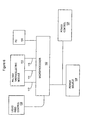
- this shows a PC 100 loaded with software algorithms set, according to the parameters of the liquid to be treated, to monitor, adjust and control the variable parameter values of a continuously operating vapour-sealed unit of the invention.
- Suitably located temperature thermistor or thermocouple sensors, liquid control valves, flow rates, volt and power measurement sensors are monitored and controlled by PC 100 through microprocessor 102.
- Microprocessor 102 is linked to low voltage (5V and 12V) DC logic power source 104, power control 106, input liquid feed monitor and control 108, and Peltier Thermoelectric Element module 110.
- temperature sensor links 112, 114 and 116 measure the temperatures of the hot evaporation surface, central portion and cooler condensing surface, respectively, of TEE module 110.
- thermoelectric module Part # HT4012-39
- Part # HT4012-39 is commercially available from MELCOR THERMOELECTRICS. Operation of this particular module at 3.5 amperes and 15.71 volts, provides a hot side temperature of 103°C.
- the hot side temperature was chosen to be 103°C in order to show the typical performance of this module when used to evaporate, at one atmosphere, a layer of water that is in contact with the hot side of the module.
- the heat pumped by the module cold side varies linearly with the cold side temperature.
- the module pumps 37 Watts at a "cold" plate temperature of 97°C, 29 Watts at a cold plate temperature of 80°C, and 10 Watts at a cold plate temperature of 34°C.
- the heat pumping efficiency is 67% (37/55), 53%, and 18% when the cold side temperature is 97°, 80° and 34°C, respectively.
- the cold plate temperature must be elevated to be close to that of the hot plate temperature. For example.
- a total heating power of 55W electrical input plus 37 Watts of pumping equals 92 Watts is applied through the hot side of the module to the water.
- the surface temperature of the water equals the temperature of the steam produced, which equals 100°C for operation at a pressure of one atmosphere.
- 92 Watts applied to the water through the hot side of the module produces steam at 100°C that has 92 Watts of latent heat.
- the surface temperature of the hot side of the module rises to higher than 100°C since additional heat is required to overcome the pressure produced by the weight of the layer of water on the hot side of the module.
- Experiments conducted with these modules show that in practice, the hot side temperature rises 3°C for every 1 cm of water thickness on the module hot side tray.
- the net effect of the module, when used to heat water, is to produce an added heating power.
- a heating power of 92 Watts is produced if the cold side is at 97°C, 84 Watts if the cold side is at 80°C, and 65 Watts if the cold side is at 34°C.
- the best utilization of the modules is when the cold side temperature is at 97°C to effectively produce 1.67 Watts of water heating power for every 1 Watt of electrical input power applied.
- Prior Art OLS DE3539086A1 uses the cold side of the modules to condense the evaporated steam that is produced by the heat transferred from the hot side of the modules into the liquid that is evaporated. If the aforesaid thermoelectric module (Part # HT4-12-30) is used in the apparatus and process described and illustrated in Figs.
- the hot side temperature of the module will eventually reach 103°C, if (a) the solvent solution to be purified is water, (b) the pressure is one atmosphere, (c) the voltage applied to the module is 15.71V, (d) the current consumed by the module is 3.5A, (e) the hot side of the module is in direct contact with the solution to be purified, and (f) the solution to be purified forms a 1 cm thick layer over the tope of the hot side of the module. As electricity is first applied to the module used in this embodiment, the temperatures of the hot side and cold side of the module are equal and assumed to be at ambient air temperature.
- the hot side receives 55 Watts of heating power, plus whatever heating power is pumped by the cold side to the hot side of the module.
- the heating power pumped from the cold side to the hot side is at least 37 Watts.
- at least 92 Watts of heating power are initially applied by the hot side of the module to the water to be purified.
- the water temperature increases to 100°C as the heating power transferred to the water from the hot side of the module increases the heat energy of the water. As the temperature of the water increases to 100°C, so does the temperature of the hot side of the module which is in direct thermal contact with the water.
- the rise in the cold side temperature must directly match the rise in the hot side temperature of the module.
- the cold side temperature will decrease below the ambient air temperature in order to maintain the Peltier heat pumping effect.
- the temperature differential between the hot and cold sides begins to increase, and at the same time the amount of heat pumping begins to decrease. This process continues until a large enough temperature differential between the hot and cold sides is produced so that the natural transfer of heat between the air at ambient temperature and the colder temperature colder side equals that rate of heat pumping from the cold side to the hot side of the module.
- the temperature of the water to be purified and the hot side of the module will eventually reach 100°C. In fact, the hot side temperature will reach 103°C.
- the heating power applied by the hot side can no longer be absorbed by the water as liquid heat energy.
- the water begins to convert into steam at an equilibrium rate so that the latent heat in the steam rising from the surface of the water equals the heat energy being applied through the hot side of the module to the water.
- the latent heating power stored in the steam rising from the surface of the water is equal to 55 Watts, plus whatever heating power is being pumped by the Peltier effect from the cold side to the hot side of the module.
- This pumped heating power can vary from 10 Watts if the cold side temperature is at 34°C, to 37 Watts if the cold side temperature is at 97°C.
- the ambient air temperature inside the apparatus described in DE3539086A1 could reasonably be assumed to be 23°C.
- minimal added heat pumping occurs during the start of the evaporation of the water to be purified.
- the ambient air temperature increases, and the natural rate of heat transfer from the ambient air to the cold side of the module increases.
- the cold side warms up until the increased heat pumping produced by the decreased temperature differential between the hot and cold sides again matches the natural rate of heat transfer from the ambient air to the cold side. Hence, a higher heat rate and heat pumping efficiency is produced.
- the apparatus and process according to the present invention achieves a continuous evaporation and condensing equilibrium inside the vessel by removing the excess latent heat from the steam via "external" heat exchanger means remote from the module cooler surface.
- "external" heat exchanger means remote from the module cooler surface For the identical module described hereinbefore, and implemented with all of the previously made assumptions, an excess heating power of 55W is removed from the vessel without the actual removal of steam.
- a secondary condensing surface remote from the module is utilized on which the remaining approximately at least 60% of the steam condenses and be collected with the no more than 40% of steam that condenses on the cold side of the module. A 100% conversion of steam to condensate can occur inside the vessel.
- An electrical power utilization efficiency of over 167% can be achieved as 55W of electrical input power produces the heating effect of 92W (55W+37W).
- the 55W of heat removed from the secondary condensing surface is most preferably reapplied to the feed water entering the vessel.
- the practical utility of the present invention is that it can achieve full evaporation and condensaticn equilibrium in the vessel, and thereby increase the throughput of the embodiment described in DE3539086A1 by, say, 250%, (i.e. 100% condensate recovery vs. 40% condensate recovery).
- Pre-heating of the incoming water to be purified also increases electrical utilization efficiency to over 167% to provide significant power savings when compared with the 95% power utilization efficiency achieved with conventional water purifiers.
Landscapes
- Chemical & Material Sciences (AREA)
- Chemical Kinetics & Catalysis (AREA)
- Life Sciences & Earth Sciences (AREA)
- Hydrology & Water Resources (AREA)
- Engineering & Computer Science (AREA)
- Environmental & Geological Engineering (AREA)
- Water Supply & Treatment (AREA)
- Organic Chemistry (AREA)
- Vaporization, Distillation, Condensation, Sublimation, And Cold Traps (AREA)
- Heat Treatment Of Water, Waste Water Or Sewage (AREA)
- Cleaning By Liquid Or Steam (AREA)
Claims (28)
- Kontinuierliches Verfahren zum Behandeln einer unreinen Flüssigkeit, um eine gereinigte Flüssigkeit zu erzeugen, wobei das genannte Verfahren das elektrische Aktivieren eines thermoelektrischen Moduls (24) zum Erzielen einer ersten modul erhitzten Oberfläche (26) und einer Modulkühleroberfläche (28), das Zuführen der genannten unreinen Flüssigkeit zu der genannten ersten modulerhitzten Oberfläche (26) zum Erzeugen von Dampf aus der genannten Flüssigkeit und das Übertragen des genannten Dampfes zu der genannten Modulkühleroberfläche (28) umfasst, um einen Wärmetransfer zu der genannten Modulkühleroberfläche (28) zu bewirken, wobei die Verbesserung Folgendes umfasst:(a) Leiten eines ersten Teils des genannten Dampfes neben oder auf die genannte Modulkühleroberfläche (28) zum Bewirken eines Wärmetransfers zu der genannten Modulkühleroberfläche (28) zum Erzeugen einer ersten kondensierten Flüssigkeit;(b) Leiten eines zweiten Teils des genannten Dampfes zum Kondensator (18, 74), umfassend eine zweite Kühleroberfläche (46) entfernt von der genannten Modulkühleroberfläche (28) zum Bewirken eines Wärmetransfers zu der genannten Kühleroberfläche (46), um eine zweite kondensierte Flüssigkeit zu erzeugen; und(c) Auffangen der genannten ersten und zweiten kondensierten Flüssigkeit; wobei der genannte Kondensator (18, 74) so gestaltet ist, dass er den Rest der latenten Wärme aufnimmt, die in dem Dampf enthalten ist, der von der genannten ersten modulerhitzten Oberfläche (26) erzeugt wird, und die nicht von der genannten Modulkühleroberfläche (28) durch das Modul (24) zu der genannten ersten modulerhitzten Oberfläche (26) gepumpt werden kann, um den Prozess unter kontinuierlichem Dampffluss zu halten.
- Verfahren nach Anspruch 1, bei dem der genannte erste Teil ein geringer Teil des genannten Dampfes und der genannte zweite Teil ein großer Teil des genannten Dampfes ist.
- Verfahren nach Anspruch 1 oder Anspruch 2, bei dem die genannte Modulkühleroberfläche (28) auf einer Temperatur auf dem oder nahe des Siedepunkt(es) der genannten Flüssigkeit ist.
- Verfahren nach einem der Ansprüche 1 bis 3, ferner umfassend das Vorheizen der genannten unreinen Flüssigkeit ganz oder teilweise durch Wärmetransfer mit latenter Wärme, die von dem genannten zweiten Teil des genannten Dampfes und dem genannten Kondensator (18, 74) erzeugt wird.
- Verfahren nach Anspruch 4, bei dem der genannte Kondensator (18) ein zweites thermoelektrisches Modul (68) mit einer zweiten Modulkühleroberfläche (70) und einer zweiten modulerhitzten Fläche (72) umfasst, Leiten des genannten zweiten Teils zu der genannten zweiten Modulkühleroberfläche (70) zum Erzeugen der genannten zweiten kondensierten Flüssigkeit, und wobei die genannte unreine Flüssigkeit ganz oder teilweise von der genannten zweiten modulerhitzten Fläche (72) vorgeheizt wird.
- Verfahren nach Anspruch 4 oder Anspruch 5, bei dem die genannte unreine Flüssigkeit erhitzt wird, um eventuelle in der genannten unreinen Flüssigkeit vorliegende flüchtige organische Verbindungen ganz oder teilweise abzudestillieren.
- Verfahren nach einem der Ansprüche 1 bis 6, ferner umfassend das Messen, Einstellen und Regeln (84, 100, 102) der Prozessparameter, die Temperatur-, Stromversorgungs- und Flüssigkeitszuführungsgeschwindigkeitswerte umfassen.
- Verfahren nach Anspruch 7, umfassend das Berechnen (100) der genannten Prozessparameterwerte in einem Algorithmus zum Einstellen der genannten Prozessparameter.
- Verfahren nach Anspruch 8, umfassend das kontinuierliche Selbstüberwachen, Einstellen und Regeln (84, 102) des Prozesses durch das genannte Berechnen (100), so dass der genannte Prozess automatisch kontinuierlich ist.
- Verfahren nach einem der Ansprüche 1 bis 9, bei dem der gesamte genannte Dampf in einer dampfdichten Einheit (12) enthalten ist.
- Flüssigkeitsreiniger (10) zum Reinigen einer Flüssigkeit unter kontinuierlichen Dampfflussbetriebsbedingungen, umfassend:ein thermoelektrisches Modul (24) mit einer ersten modulerhitzbaren Oberfläche (26) und einer ersten modulkühlbaren Oberfläche (28);ein Rohr (34) zum Bewirken eines Kontakts der genannten unreinen Flüssigkeit mit der genannten modulerhitzbaren Oberfläche (26), um Dampf aus der genannten Flüssigkeit zu erzeugen;eine Dampfübertragungsführung (42) zum Übertragen des genannten Dampfes zu der genannten ersten modulkühlbaren Oberfläche (28) zum Bewirken eines Wärmetransfers zu der genannten modulkühlbaren Oberfläche (28) und zum Kondensieren des genannten Dampfes zu der genannten gereinigten Flüssigkeit; undein Empfängerrohr (14) zum Auffangen der genannten gereinigten Flüssigkeit; wobei das genannte Modul (24) so gestaltet ist, dass es einen elektrischen Strom (80, 82) zum Aktivieren des genannten Moduls (24) zum Erhitzen der genannten erhitzbaren Oberfläche (26) und zum Kühlen der genannten kühlbaren Oberfläche (28) empfängt; wobei die Verbesserung Folgendes umfasst:(i) eine erste Führung (42) zum Leiten eines ersten Teils des genannten Dampfes neben oder auf die genannte erste modulkühlbare Oberfläche (28), um funktionell einen Wärmetransfer zu der genannten ersten modulkühlbaren Oberfläche (28) zum Erzeugen einer ersten kondensierten Flüssigkeit zu bewirken;(ii) einen Kondensator (18, 74), umfassend eine zweite kühlbare Oberfläche (46) entfernt von der genannten modulkühlbaren Oberfläche (28) zum Kondensieren eines zweiten Teils des genannten Dampfes durch Wärmetransfer zu der genannten zweiten kühlbaren Oberfläche (46), um eine zweite kondensierte Flüssigkeit zu erzeugen;(iii) eine Dampfleitung (C) zum funktionellen Leiten des genannten zweiten Teils des genannten Dampfes zu dem genannten Kondensator (18, 74);(iv) ein Empfängerrohr (14) zum Auffangen der genannten ersten und zweiten kondensierten Flüssigkeit; und wobei der genannte Kondensator (18, 74) und die genannte Dampfleitung (C) so gestaltet sind, dass sie es ermöglichen, dass der Rest der latenten Wärme, die in dem Dampf enthalten ist, der von der genannten ersten modulerhitzten Oberfläche (26) enthalten ist, und die nicht von der genannten Kühlmoduloberfläche (28) durch das Modul (24) zu der genannten ersten modulerhitzten Oberfläche (26) gepumpt werden kann, funktionell von dem genannten Kondensator (18, 74) aufgenommen wird, um den Prozess unter kontinuierlichem Dampffluss zu halten.
- Reiniger (10) nach Anspruch 11, ferner umfassend Vorheizmodule (68) zum Vorheizen der genannten unreinen Flüssigkeit ganz oder teilweise durch Wärmetransfer mit dem genannten Kondensator (18, 74).
- Reiniger (10) nach Anspruch 12, wobei das genannte Vorheizmodul (68) ein zweites thermoelektrisches Modul (68) mit einer zweiten modulerhitzbaren Oberfläche (72) und einer zweiten modulkühlbaren Oberfläche (70) umfasst, wobei im Wesentlichen der genannte zweite Teil des genannten Dampfes kondensiert wird, um im Wesentlichen die genannte zweite kondensierte Flüssigkeit zu erzeugen, und die genannte unreine Flüssigkeit von der genannten zweiten erhitzbaren Oberfläche (72) funktionell erhitzt wird.
- Reiniger (10) nach Anspruch 13, wobei die genannte zweite kühlbare Oberfläche (46) entfernt von dem genannten Modul (24) als die genannte zweite modulkühlbare Oberfläche (70) gebildet wird.
- Reiniger (10) nach Anspruch 11 zum Reinigen einer Flüssigkeit, umfassend:(a) ein Gehäuse (12) mit einer ersten Kammer (B) und einer zweiten Kammer (A);(b) einen Teiler (20), der die erste (B) und die zweite (A) Kammer voneinander trennt; wobei der Teiler ein thermoelektrisches Modul (24) mit einer in der ersten Kammer (B) aufgenommenen modulerhitzbaren Oberfläche (26) und einer in der zweiten Kammer (A) aufgenommenen modulkühlbaren Oberfläche (28) umfasst;(c) ein Rohr (34), um die unreine Flüssigkeit funktionell mit der erhitzbaren Oberfläche (26) in der ersten Kammer (B) zum Erzeugen von Dampf in Kontakt zu bringen;(d) eine erste Übertragungsführung (42) zum Leiten eines ersten Teils des Dampfes neben oder auf die modulkühlbare Oberfläche (28), um einen Wärmetransfer zu der modulkühlbaren Oberfläche (28) zum Erzeugen einer ersten kondensierten Flüssigkeit zu bewirken;(e) einen Kondensator (18, 74) entfernt von der modulkühlbaren Oberfläche (28), umfassend eine zweite kühlbare Oberfläche (46) zum Kondensieren eines zweiten Teils des Dampfes durch Wärmetransfer zum Erzeugen einer zweiten kondensierten Flüssigkeit;(f) eine zweite Übertragungskammer (A) zum Leiten des zweiten Teils des Dampfes zu dem Kondensator (18);(g) ein Auffangrohr (14) zum Auffangen der ersten und der zweiten kondensierten Flüssigkeit;(h) einen thermoelektrischen Moduladapter (80, 82, 84), wobei das Modul (24) funktionell einen elektrischen Strom zum Erhitzen der modulerhitzbaren Oberfläche (26) und zum Kühlen der modulkühlbaren Oberfläche (28) empfangen kann; und wobei der genannte Kondensator (18, 74) und die genannte Übertragungskammer (A) so gestaltet sind, dass sie es ermöglichen, dass der Rest der latenten Wärme, die in dem Dampf enthalten ist, der von der genannten ersten modulerhitzten Oberfläche (26) erzeugt wird, und die nicht von der genannten Kühlmoduloberfläche (28) durch das Modul (24) zu der genannten ersten modulerhitzten Oberfläche (26) gepumpt werden kann, um von dem genannten Kondensator (18, 74) funktionell aufgenommen zu werden, um den Prozess unter kontinuierlichem Dampffluss zu halten.
- Reiniger (10) nach Anspruch 15, bei dem sich die genannte kühlbare Oberfläche (46) in der genannten zweiten Kammer (A) befindet.
- Reiniger (10) nach Anspruch 16, ferner umfassend eine Unreine-Flüssigkeit-Speiseleitung (34), die vertikal in der genannten ersten Kammer (B) oberhalb der genannten modulerhitzbaren Oberfläche (26) angeordnet ist, um einen Kontakt zwischen der genannten Speiseflüssigkeit und der genannten modulerhitzbaren Oberfläche (26) zu ermöglichen.
- Reiniger (10) nach Anspruch 15 oder Anspruch 16, bei dem die genannte zweite Kammer (A) durch eine vertikale Wand (36), eine Bodenwand (16) und eine Deckenwand (18) mit einer inneren Kammeroberfläche (46) definiert wird; und mit einem Kondensator (36) neben der genannten Deckenwand (18) zum Kühlen der genannten inneren Kammeroberfläche (46), um die Kondensation des genannten großen Teils des genannten Dampfes zu bewirken.
- Reiniger (10) nach Anspruch 18, wobei in dem genannten Kondensator (36) die genannte Deckenwand (18) mit einem Kühlfluid in Kontakt gebracht werden kann.
- Reiniger (10) nach Anspruch 19, bei dem das genannte Fluid kalte Luft oder kaltes Wasser ist.
- Reiniger (10) nach Anspruch 18, wobei die genannte Deckenwand (18) ein zweites thermoelektrisches Modul (68) mit einer zweiten modulerhitzbaren Oberfläche (72) und einer zweiten modulkühlbaren Oberfläche (70) umfasst, wobei die genannte zweite modulkühlbare Oberfläche (70) mit dem genannten zweiten Teil des genannten Dampfes in Kontakt kommen kann, so dass die genannte zweite kondensierte Flüssigkeit erzeugt wird.
- Reiniger (10) nach Anspruch 18, ferner umfassend ein zweites thermoelektrisches Modul (68) mit einer zweiten modulerhitzbaren Oberfläche (72) und einer zweiten modulkühlbaren Oberfläche (70), wobei die genannte Deckenwand (18) an die genannte zweite modulkühlbare Oberfläche (70) anstößt, um von ihr gekühlt zu werden, um die Kondensation des genannten zweiten Teils des genannten Dampfes zum Erzeugen der genannten zweiten kondensierten Flüssigkeit zu bewirken.
- Reiniger (10) nach Anspruch 11, wobei der genannte Kondensator (74) eine Kondensatorspule (74) umfasst.
- Reiniger (10) nach Anspruch 23, wobei der genannte Kondensator (74) ein Modul (68) zum Vorheizen der genannten unreinen Speiseflüssigkeit bildet.
- Reiniger (10) nach einem der Ansprüche 11 bis 24, ferner umfassend Prozesslenkung (84, 100; 102) zum Messen, Regeln und Einstellen der Prozessparameter.
- Reiniger (10) nach Anspruch 25, wobei die genannte Prozesslenkung Folgendes umfasst:(a) einen Computeralgorithmus-Mikroprozessor (84, 102);(b) einen Temperatursensor, eine Stromversorgung, Messung, Einstellung und Regelung (84, 102) und(c) ein Speiseflüssigkeitseingangsventil (60).
- Reiniger (10) nach Anspruch 26, wobei die genannten Rechenmittel (84, 102) eine kontinuierliche Selbstüberwachung des Prozesses ermöglichen.
- Reiniger (10) nach einem der Ansprüche 11 bis 27, der eine dampfdichte, eigenständige Einheit (12) zum Aufnehmen des gesamten genannten Dampfes umfasst.
Applications Claiming Priority (3)
| Application Number | Priority Date | Filing Date | Title |
|---|---|---|---|
| CA2292383 | 1999-12-17 | ||
| CA002292383A CA2292383A1 (en) | 1999-12-17 | 1999-12-17 | Apparatus and process for purifying a liquid |
| PCT/CA2000/001482 WO2001045816A1 (en) | 1999-12-17 | 2000-12-15 | Apparatus and process for purifying a liquid by thermoelectric peltier means |
Publications (2)
| Publication Number | Publication Date |
|---|---|
| EP1239933A1 EP1239933A1 (de) | 2002-09-18 |
| EP1239933B1 true EP1239933B1 (de) | 2005-03-23 |
Family
ID=4164894
Family Applications (1)
| Application Number | Title | Priority Date | Filing Date |
|---|---|---|---|
| EP00984713A Expired - Lifetime EP1239933B1 (de) | 1999-12-17 | 2000-12-15 | Vorrichtung und verfahren zur reinigung einer flüssigkeit mit einem thermoelektrischen peltierelement |
Country Status (5)
| Country | Link |
|---|---|
| US (1) | US6805774B2 (de) |
| EP (1) | EP1239933B1 (de) |
| AT (1) | ATE291475T1 (de) |
| CA (2) | CA2292383A1 (de) |
| DE (1) | DE60018972D1 (de) |
Families Citing this family (18)
| Publication number | Priority date | Publication date | Assignee | Title |
|---|---|---|---|---|
| US6921858B2 (en) * | 2002-11-08 | 2005-07-26 | Bechtel Bwxt Idaho, Llc | Method and apparatus for pressurizing a liquefied gas |
| US7159404B2 (en) * | 2005-05-26 | 2007-01-09 | Country Pure Foods, Llc | System and method for storing a product in a thermally stabilized state |
| WO2007096917A1 (en) * | 2006-02-27 | 2007-08-30 | A. Celli Nonwovens S.P.A. | Machine for winding weblike material in reels, with pairs of supports for winding rods |
| WO2009138818A1 (en) * | 2008-05-14 | 2009-11-19 | Smit, Petrus Johannes Joachim | Distillation apparatus |
| US8495893B2 (en) * | 2009-01-08 | 2013-07-30 | Ali Alajimi | Hybrid apparatus for cooling water and air and heating water |
| ES2864207T3 (es) * | 2009-09-21 | 2021-10-13 | Epiphany Solar Water Systems | Sistema de purificación de agua alimentado por energía solar |
| US8709216B2 (en) * | 2011-01-22 | 2014-04-29 | Dwight L. Jaeger | Fresh water recovery system |
| US11261114B2 (en) | 2015-07-21 | 2022-03-01 | David DeChristofaro | Aerobic treatment system |
| EP3357869A1 (de) * | 2017-02-01 | 2018-08-08 | mittemitte GmbH | Wasserreinigungssystem und destillationseinheit |
| WO2018191517A1 (en) * | 2017-04-13 | 2018-10-18 | Benz Research And Development Corp. | Water purification device |
| BR112020018501A2 (pt) * | 2018-03-13 | 2020-12-29 | Geniver Llc | Método e aparelho para purificação e remineralização de água |
| WO2020123982A2 (en) | 2018-12-14 | 2020-06-18 | Benz Research And Development Corp. | Refining system |
| KR102280251B1 (ko) * | 2019-09-16 | 2021-07-21 | 하이리움산업㈜ | 열전 극저온 물질 저장용기 |
| US12502834B2 (en) * | 2020-01-06 | 2025-12-23 | Sprintray, Inc. | Multi-stage wash system for vat polymerization-based 3D printed parts |
| GB2590533B (en) | 2020-10-06 | 2022-01-12 | Namaya Mineral Water Ltd | System and process of mineralizing distilled water with replenishable mineral concentrate solutions |
| CN113385246B (zh) * | 2021-02-04 | 2022-07-19 | 唐飞鹏 | 一种共沸恒温加热装置 |
| KR20240110016A (ko) * | 2021-11-09 | 2024-07-12 | 램 리써치 코포레이션 | 기판 프로세싱 시스템들을 위한 컴팩트한 인 시츄 가스 분리기 |
| CN115970314B (zh) * | 2023-03-17 | 2023-06-02 | 河北新启元能源技术开发股份有限公司 | 一种绿色低碳丁烷法的真空产品塔 |
Family Cites Families (16)
| Publication number | Priority date | Publication date | Assignee | Title |
|---|---|---|---|---|
| US3212999A (en) | 1957-07-30 | 1965-10-19 | Rca Corp | Purification apparatus utilizing a thermoelectric heat pump |
| US3261764A (en) | 1963-06-17 | 1966-07-19 | Casey Cullen | Thermoelectric heater for liquid concentrating still |
| US3671404A (en) | 1968-07-12 | 1972-06-20 | Milton Meckler | Peltier effect concentric still with high temperature heat supplying means |
| DE3539086A1 (de) | 1985-11-04 | 1987-05-07 | Wagner Finish Tech Center Gmbh | Vorrichtung zum wiedergewinnen von loesungsmitteln in der oberflaechentechnik |
| US4792059A (en) | 1987-02-04 | 1988-12-20 | United States Thermoelectric Corporation | Sealed hot, cold and room temperature pure water dispenser |
| JPH01184094A (ja) | 1988-01-18 | 1989-07-21 | Noriharu Nakamura | 浄水装置 |
| DE4011877A1 (de) | 1990-04-12 | 1991-10-17 | Vacutec Anlagen Und Verfahrens | Waermepumpenverfahren zur destillation und trocknung |
| AU5683294A (en) * | 1992-11-27 | 1994-06-22 | Pneumo Abex Corporation | Thermoelectric device for heating and cooling air for human use |
| US5587055A (en) | 1993-10-26 | 1996-12-24 | Michael O. Hartman | Water distilling apparatus and method |
| JPH07209841A (ja) | 1994-01-18 | 1995-08-11 | Koichi Hayashi | 現像廃液濃縮装置 |
| US5581055A (en) | 1995-08-04 | 1996-12-03 | Kevin G. Self | Muffler for air operated hand tools and other pneumatic devices |
| EP0837290B1 (de) * | 1996-10-16 | 2003-04-23 | Thermovonics Co., Ltd | Wasserkühler |
| FR2757420B1 (fr) | 1996-12-24 | 1999-02-12 | Tournaire Sa | Dispositif compact de regeneration de solvants |
| CA2241168A1 (en) | 1998-06-19 | 1999-12-19 | Youssef Hanna Dableh | Water purifying apparatus and process |
| US6164076A (en) * | 1999-08-05 | 2000-12-26 | International Business Machines Corporation | Thermoelectric cooling assembly with thermal space transformer interposed between cascaded thermoelectric stages for improved thermal performance |
| US6375805B1 (en) * | 1999-12-17 | 2002-04-23 | Youssef Hanna Dableh | Apparatus and process for purifying a liquid |
-
1999
- 1999-12-17 CA CA002292383A patent/CA2292383A1/en not_active Withdrawn
-
2000
- 2000-12-15 DE DE60018972T patent/DE60018972D1/de not_active Expired - Lifetime
- 2000-12-15 US US10/110,127 patent/US6805774B2/en not_active Expired - Lifetime
- 2000-12-15 EP EP00984713A patent/EP1239933B1/de not_active Expired - Lifetime
- 2000-12-15 AT AT00984713T patent/ATE291475T1/de not_active IP Right Cessation
- 2000-12-15 CA CA002388194A patent/CA2388194C/en not_active Expired - Fee Related
Also Published As
| Publication number | Publication date |
|---|---|
| ATE291475T1 (de) | 2005-04-15 |
| DE60018972D1 (de) | 2005-04-28 |
| CA2292383A1 (en) | 2001-06-17 |
| US20020179425A1 (en) | 2002-12-05 |
| EP1239933A1 (de) | 2002-09-18 |
| US6805774B2 (en) | 2004-10-19 |
| CA2388194C (en) | 2008-03-25 |
| CA2388194A1 (en) | 2001-06-28 |
Similar Documents
| Publication | Publication Date | Title |
|---|---|---|
| US6805774B2 (en) | Apparatus and process for purifying a liquid by thermoelectric peltier means | |
| US6375805B1 (en) | Apparatus and process for purifying a liquid | |
| US20190352193A1 (en) | Device for the Purification of Water Using a Heat Pump | |
| US7089762B2 (en) | Multi-stage vacuum distilling, cooling and freezing processes and apparatuses for solution separation and seawater desalination | |
| US10759677B2 (en) | Self-contained photovoltaic distillation apparatus | |
| WO1999033751A1 (en) | Desalination method and desalination apparatus | |
| KR860001490B1 (ko) | 염수로부터 청수(淸水)를 얻기위한 염수의 증류방법 및 장치 | |
| WO2020056847A1 (zh) | 一种集成半导体热泵的多级膜组件及其在膜蒸馏中的应用 | |
| US20220347595A1 (en) | Self-contained photovoltaic distillation apparatus | |
| WO2009138818A1 (en) | Distillation apparatus | |
| Afaneh et al. | Novel integration of thermoelectric distiller with direct contact membrane distillation | |
| GB2035813A (en) | Heat pump type water distilling apparatus | |
| WO2009065407A2 (en) | Integrated solar collector and multiple effect distillation | |
| RU2761832C1 (ru) | Энергонезависимая солнечная дистилляционная система непрерывного действия (варианты) | |
| US20090255797A1 (en) | Apparatus for desalinization utilizingtemperature gradient/condensation and method thereof | |
| WO2014205430A1 (en) | Waste-heat water distillation system | |
| US3393130A (en) | Peltier effect concentric still | |
| US12065362B2 (en) | Vacuum assisted liquid separation system | |
| US10022646B1 (en) | Solar cooling and water salination system | |
| CA2241168A1 (en) | Water purifying apparatus and process | |
| CN115966328B (zh) | 放射性废液处理方法和系统 | |
| SU1599031A1 (ru) | Выпарна установка | |
| Abdelrehim et al. | Performance analysis of high concentration Photovoltaic/Membrane distillation hybrid system | |
| WO2002062708A1 (en) | Method and device for production of distilled fluid and exergy | |
| US3511756A (en) | Flash evaporation with series arranged with solar heating zone |
Legal Events
| Date | Code | Title | Description |
|---|---|---|---|
| PUAI | Public reference made under article 153(3) epc to a published international application that has entered the european phase |
Free format text: ORIGINAL CODE: 0009012 |
|
| 17P | Request for examination filed |
Effective date: 20020429 |
|
| AK | Designated contracting states |
Kind code of ref document: A1 Designated state(s): AT BE CH CY DE DK ES FI FR GB GR IE IT LI LU MC NL PT SE TR |
|
| AX | Request for extension of the european patent |
Free format text: AL;LT;LV;MK;RO;SI |
|
| 17Q | First examination report despatched |
Effective date: 20021104 |
|
| GRAP | Despatch of communication of intention to grant a patent |
Free format text: ORIGINAL CODE: EPIDOSNIGR1 |
|
| GRAS | Grant fee paid |
Free format text: ORIGINAL CODE: EPIDOSNIGR3 |
|
| GRAA | (expected) grant |
Free format text: ORIGINAL CODE: 0009210 |
|
| AK | Designated contracting states |
Kind code of ref document: B1 Designated state(s): AT BE CH CY DE DK ES FI FR GB GR IE IT LI LU MC NL PT SE TR |
|
| PG25 | Lapsed in a contracting state [announced via postgrant information from national office to epo] |
Ref country code: AT Free format text: LAPSE BECAUSE OF FAILURE TO SUBMIT A TRANSLATION OF THE DESCRIPTION OR TO PAY THE FEE WITHIN THE PRESCRIBED TIME-LIMIT Effective date: 20050323 Ref country code: IT Free format text: LAPSE BECAUSE OF FAILURE TO SUBMIT A TRANSLATION OF THE DESCRIPTION OR TO PAY THE FEE WITHIN THE PRESCRIBED TIME-LIMIT;WARNING: LAPSES OF ITALIAN PATENTS WITH EFFECTIVE DATE BEFORE 2007 MAY HAVE OCCURRED AT ANY TIME BEFORE 2007. THE CORRECT EFFECTIVE DATE MAY BE DIFFERENT FROM THE ONE RECORDED. Effective date: 20050323 Ref country code: BE Free format text: LAPSE BECAUSE OF FAILURE TO SUBMIT A TRANSLATION OF THE DESCRIPTION OR TO PAY THE FEE WITHIN THE PRESCRIBED TIME-LIMIT Effective date: 20050323 Ref country code: CH Free format text: LAPSE BECAUSE OF FAILURE TO SUBMIT A TRANSLATION OF THE DESCRIPTION OR TO PAY THE FEE WITHIN THE PRESCRIBED TIME-LIMIT Effective date: 20050323 Ref country code: FI Free format text: LAPSE BECAUSE OF FAILURE TO SUBMIT A TRANSLATION OF THE DESCRIPTION OR TO PAY THE FEE WITHIN THE PRESCRIBED TIME-LIMIT Effective date: 20050323 Ref country code: TR Free format text: LAPSE BECAUSE OF FAILURE TO SUBMIT A TRANSLATION OF THE DESCRIPTION OR TO PAY THE FEE WITHIN THE PRESCRIBED TIME-LIMIT Effective date: 20050323 Ref country code: NL Free format text: LAPSE BECAUSE OF FAILURE TO SUBMIT A TRANSLATION OF THE DESCRIPTION OR TO PAY THE FEE WITHIN THE PRESCRIBED TIME-LIMIT Effective date: 20050323 Ref country code: LI Free format text: LAPSE BECAUSE OF FAILURE TO SUBMIT A TRANSLATION OF THE DESCRIPTION OR TO PAY THE FEE WITHIN THE PRESCRIBED TIME-LIMIT Effective date: 20050323 |
|
| REG | Reference to a national code |
Ref country code: GB Ref legal event code: FG4D |
|
| REG | Reference to a national code |
Ref country code: CH Ref legal event code: EP |
|
| REG | Reference to a national code |
Ref country code: IE Ref legal event code: FG4D |
|
| REF | Corresponds to: |
Ref document number: 60018972 Country of ref document: DE Date of ref document: 20050428 Kind code of ref document: P |
|
| PG25 | Lapsed in a contracting state [announced via postgrant information from national office to epo] |
Ref country code: DK Free format text: LAPSE BECAUSE OF FAILURE TO SUBMIT A TRANSLATION OF THE DESCRIPTION OR TO PAY THE FEE WITHIN THE PRESCRIBED TIME-LIMIT Effective date: 20050623 Ref country code: GR Free format text: LAPSE BECAUSE OF FAILURE TO SUBMIT A TRANSLATION OF THE DESCRIPTION OR TO PAY THE FEE WITHIN THE PRESCRIBED TIME-LIMIT Effective date: 20050623 |
|
| PG25 | Lapsed in a contracting state [announced via postgrant information from national office to epo] |
Ref country code: DE Free format text: LAPSE BECAUSE OF FAILURE TO SUBMIT A TRANSLATION OF THE DESCRIPTION OR TO PAY THE FEE WITHIN THE PRESCRIBED TIME-LIMIT Effective date: 20050624 |
|
| PG25 | Lapsed in a contracting state [announced via postgrant information from national office to epo] |
Ref country code: ES Free format text: LAPSE BECAUSE OF FAILURE TO SUBMIT A TRANSLATION OF THE DESCRIPTION OR TO PAY THE FEE WITHIN THE PRESCRIBED TIME-LIMIT Effective date: 20050704 |
|
| NLV1 | Nl: lapsed or annulled due to failure to fulfill the requirements of art. 29p and 29m of the patents act | ||
| PG25 | Lapsed in a contracting state [announced via postgrant information from national office to epo] |
Ref country code: PT Free format text: LAPSE BECAUSE OF FAILURE TO SUBMIT A TRANSLATION OF THE DESCRIPTION OR TO PAY THE FEE WITHIN THE PRESCRIBED TIME-LIMIT Effective date: 20050907 |
|
| REG | Reference to a national code |
Ref country code: CH Ref legal event code: PL |
|
| ET | Fr: translation filed | ||
| PG25 | Lapsed in a contracting state [announced via postgrant information from national office to epo] |
Ref country code: IE Free format text: LAPSE BECAUSE OF NON-PAYMENT OF DUE FEES Effective date: 20051215 Ref country code: CY Free format text: LAPSE BECAUSE OF FAILURE TO SUBMIT A TRANSLATION OF THE DESCRIPTION OR TO PAY THE FEE WITHIN THE PRESCRIBED TIME-LIMIT Effective date: 20051215 |
|
| PG25 | Lapsed in a contracting state [announced via postgrant information from national office to epo] |
Ref country code: MC Free format text: LAPSE BECAUSE OF NON-PAYMENT OF DUE FEES Effective date: 20051231 Ref country code: LU Free format text: LAPSE BECAUSE OF NON-PAYMENT OF DUE FEES Effective date: 20051231 |
|
| PLBE | No opposition filed within time limit |
Free format text: ORIGINAL CODE: 0009261 |
|
| STAA | Information on the status of an ep patent application or granted ep patent |
Free format text: STATUS: NO OPPOSITION FILED WITHIN TIME LIMIT |
|
| 26N | No opposition filed |
Effective date: 20051227 |
|
| REG | Reference to a national code |
Ref country code: IE Ref legal event code: MM4A |
|
| PGFP | Annual fee paid to national office [announced via postgrant information from national office to epo] |
Ref country code: FR Payment date: 20061221 Year of fee payment: 7 |
|
| PG25 | Lapsed in a contracting state [announced via postgrant information from national office to epo] |
Ref country code: SE Free format text: LAPSE BECAUSE OF FAILURE TO SUBMIT A TRANSLATION OF THE DESCRIPTION OR TO PAY THE FEE WITHIN THE PRESCRIBED TIME-LIMIT Effective date: 20050623 |
|
| PGFP | Annual fee paid to national office [announced via postgrant information from national office to epo] |
Ref country code: GB Payment date: 20071010 Year of fee payment: 8 |
|
| REG | Reference to a national code |
Ref country code: FR Ref legal event code: ST Effective date: 20081020 |
|
| PG25 | Lapsed in a contracting state [announced via postgrant information from national office to epo] |
Ref country code: FR Free format text: LAPSE BECAUSE OF NON-PAYMENT OF DUE FEES Effective date: 20071231 |
|
| GBPC | Gb: european patent ceased through non-payment of renewal fee |
Effective date: 20081215 |
|
| PG25 | Lapsed in a contracting state [announced via postgrant information from national office to epo] |
Ref country code: GB Free format text: LAPSE BECAUSE OF NON-PAYMENT OF DUE FEES Effective date: 20081215 |