EP1241381A2 - Dispositif de sélection pour boíte de vitesses - Google Patents
Dispositif de sélection pour boíte de vitesses Download PDFInfo
- Publication number
- EP1241381A2 EP1241381A2 EP02009238A EP02009238A EP1241381A2 EP 1241381 A2 EP1241381 A2 EP 1241381A2 EP 02009238 A EP02009238 A EP 02009238A EP 02009238 A EP02009238 A EP 02009238A EP 1241381 A2 EP1241381 A2 EP 1241381A2
- Authority
- EP
- European Patent Office
- Prior art keywords
- shift control
- control lever
- shift
- shaft
- guide member
- Prior art date
- Legal status (The legal status is an assumption and is not a legal conclusion. Google has not performed a legal analysis and makes no representation as to the accuracy of the status listed.)
- Withdrawn
Links
- 230000005540 biological transmission Effects 0.000 title claims abstract description 48
- 230000001105 regulatory effect Effects 0.000 claims description 46
- 230000001154 acute effect Effects 0.000 claims description 34
- 238000010586 diagram Methods 0.000 description 21
- 239000013598 vector Substances 0.000 description 14
- 238000003780 insertion Methods 0.000 description 4
- 230000037431 insertion Effects 0.000 description 4
- 230000004048 modification Effects 0.000 description 4
- 238000012986 modification Methods 0.000 description 4
- 208000024335 physical disease Diseases 0.000 description 3
- 238000010276 construction Methods 0.000 description 2
- 238000005452 bending Methods 0.000 description 1
- 238000006073 displacement reaction Methods 0.000 description 1
- 230000007257 malfunction Effects 0.000 description 1
- 230000007935 neutral effect Effects 0.000 description 1
Images




Classifications
-
- B—PERFORMING OPERATIONS; TRANSPORTING
- B60—VEHICLES IN GENERAL
- B60K—ARRANGEMENT OR MOUNTING OF PROPULSION UNITS OR OF TRANSMISSIONS IN VEHICLES; ARRANGEMENT OR MOUNTING OF PLURAL DIVERSE PRIME-MOVERS IN VEHICLES; AUXILIARY DRIVES FOR VEHICLES; INSTRUMENTATION OR DASHBOARDS FOR VEHICLES; ARRANGEMENTS IN CONNECTION WITH COOLING, AIR INTAKE, GAS EXHAUST OR FUEL SUPPLY OF PROPULSION UNITS IN VEHICLES
- B60K20/00—Arrangement or mounting of change-speed gearing control devices in vehicles
- B60K20/02—Arrangement or mounting of change-speed gearing control devices in vehicles of initiating means
- B60K20/06—Arrangement or mounting of change-speed gearing control devices in vehicles of initiating means mounted on steering column or the like
-
- F—MECHANICAL ENGINEERING; LIGHTING; HEATING; WEAPONS; BLASTING
- F16—ENGINEERING ELEMENTS AND UNITS; GENERAL MEASURES FOR PRODUCING AND MAINTAINING EFFECTIVE FUNCTIONING OF MACHINES OR INSTALLATIONS; THERMAL INSULATION IN GENERAL
- F16H—GEARING
- F16H59/00—Control inputs to control units of change-speed- or reversing-gearings for conveying rotary motion
- F16H59/02—Selector apparatus
- F16H59/08—Range selector apparatus
- F16H59/10—Range selector apparatus comprising levers
-
- Y—GENERAL TAGGING OF NEW TECHNOLOGICAL DEVELOPMENTS; GENERAL TAGGING OF CROSS-SECTIONAL TECHNOLOGIES SPANNING OVER SEVERAL SECTIONS OF THE IPC; TECHNICAL SUBJECTS COVERED BY FORMER USPC CROSS-REFERENCE ART COLLECTIONS [XRACs] AND DIGESTS
- Y10—TECHNICAL SUBJECTS COVERED BY FORMER USPC
- Y10T—TECHNICAL SUBJECTS COVERED BY FORMER US CLASSIFICATION
- Y10T74/00—Machine element or mechanism
- Y10T74/20—Control lever and linkage systems
- Y10T74/20012—Multiple controlled elements
- Y10T74/20018—Transmission control
-
- Y—GENERAL TAGGING OF NEW TECHNOLOGICAL DEVELOPMENTS; GENERAL TAGGING OF CROSS-SECTIONAL TECHNOLOGIES SPANNING OVER SEVERAL SECTIONS OF THE IPC; TECHNICAL SUBJECTS COVERED BY FORMER USPC CROSS-REFERENCE ART COLLECTIONS [XRACs] AND DIGESTS
- Y10—TECHNICAL SUBJECTS COVERED BY FORMER USPC
- Y10T—TECHNICAL SUBJECTS COVERED BY FORMER US CLASSIFICATION
- Y10T74/00—Machine element or mechanism
- Y10T74/20—Control lever and linkage systems
- Y10T74/20012—Multiple controlled elements
- Y10T74/20018—Transmission control
- Y10T74/2014—Manually operated selector [e.g., remotely controlled device, lever, push button, rotary dial, etc.]
-
- Y—GENERAL TAGGING OF NEW TECHNOLOGICAL DEVELOPMENTS; GENERAL TAGGING OF CROSS-SECTIONAL TECHNOLOGIES SPANNING OVER SEVERAL SECTIONS OF THE IPC; TECHNICAL SUBJECTS COVERED BY FORMER USPC CROSS-REFERENCE ART COLLECTIONS [XRACs] AND DIGESTS
- Y10—TECHNICAL SUBJECTS COVERED BY FORMER USPC
- Y10T—TECHNICAL SUBJECTS COVERED BY FORMER US CLASSIFICATION
- Y10T74/00—Machine element or mechanism
- Y10T74/20—Control lever and linkage systems
- Y10T74/20012—Multiple controlled elements
- Y10T74/20018—Transmission control
- Y10T74/2014—Manually operated selector [e.g., remotely controlled device, lever, push button, rotary dial, etc.]
- Y10T74/20146—Control lever on steering column
-
- Y—GENERAL TAGGING OF NEW TECHNOLOGICAL DEVELOPMENTS; GENERAL TAGGING OF CROSS-SECTIONAL TECHNOLOGIES SPANNING OVER SEVERAL SECTIONS OF THE IPC; TECHNICAL SUBJECTS COVERED BY FORMER USPC CROSS-REFERENCE ART COLLECTIONS [XRACs] AND DIGESTS
- Y10—TECHNICAL SUBJECTS COVERED BY FORMER USPC
- Y10T—TECHNICAL SUBJECTS COVERED BY FORMER US CLASSIFICATION
- Y10T74/00—Machine element or mechanism
- Y10T74/20—Control lever and linkage systems
- Y10T74/20012—Multiple controlled elements
- Y10T74/20018—Transmission control
- Y10T74/2014—Manually operated selector [e.g., remotely controlled device, lever, push button, rotary dial, etc.]
- Y10T74/20146—Control lever on steering column
- Y10T74/20152—Control lever movable through plural planes
Definitions
- the present invention relates to a shift control device for a transmission mechanism of a motor vehicle, and more particularly to a column-type shift control device.
- a column-type shift control device is now used on a part of motor vehicles equipped with an automatic transmission (AT) or a continuously variable transmission (CVT).
- AT automatic transmission
- CVT continuously variable transmission
- a shift control lever provided in the vicinity of a steering wheel is swung about a lever mounting axis or pulled up to thereby set a desired shift range.
- the column-type shift control device can help expand the effective space within a passenger compartment of a motor vehicle and improve the occupying properties thereof, much attention being thus paid to the latter.
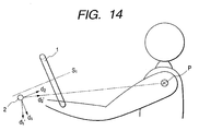
- Fig. 14 is a drawing explaining a conventional column-type shift control device.
- reference numerals 1 and 2 denote a steering wheel and a shift control lever for column shifting, respectively.
- the steering wheel 1 is mounted on a steering shaft not shown
- the shift control lever 2 is mounted on a shift shaft not shown.
- the conventional shift control device is mounted such that an axis S1 of the steering shaft is parallel with an axis of the shift shaft. Therefore, when the shift control lever 2 is swung (moved in a direction indicated by reference numeral d1), the shift shaft rotates through an angle corresponding to a distance that the shift control lever is shifted.
- the driver When thinking of swing operations by the driver, the driver tends to rotate the shift control lever 2 at a distance equal to a distance from the rotational center P of his or her shoulder to the shift control lever 2. In other words, the driver tends to swing the shift control lever while pulling it up by a distance equal to a deviation between the direction d1' and the intended direction d1. If a distance the shift control lever 2 is pulled up due to the aforesaid lever operation exceeds a predetermined pull-up distance which regulates lever shifting between two gear positions, an unintended gear position (for instance, a parking gear position) is engaged irrespective of a driver's intention to engage a currently intended gear position (for instance, a drive range position).
- a predetermined pull-up distance which regulates lever shifting between two gear positions
- the shift control lever 2 tends to be shifted toward the direction d2' .
- the driver tends to pull up the shift control lever 2 while applying thereto a force in a direction deviating from the intended direction d2 toward the direction d1'.
- the shift control lever 2 is shifted in the direction d2 which is different from the driver's intended direction d2' . As a result of this, there maybe a risk of the driver eventually feeling an unnatural shift lever operation feeling.
- a first aspect of the present invention provides a shift control device for a transmission mechanism for a motor vehicle in which gear shifting is performed by a shift control lever provided in the vicinity of a steering wheel for column shifting, comprising:
- a second aspect of the present invention provides a shift control device for a transmission mechanism for a motor vehicle in which gear shifting is performed by a shift control lever provided in the vicinity of a steering wheel for column shifting, comprising:
- a third aspect of the present invention provides a shift control device for a transmission mechanism for a motor vehicle in which gear shifting is performed by a shift control lever provided in the vicinity of a steering wheel for column shifting, having a guide member movable in a first direction by swing operating the shift control lever and in a second direction different from the first direction by pull-up operating the shift control lever; and a regulating member having a slidable portion for regulating a direction in which the shift control lever is pulled up through abutment with the guide member; and wherein a travelling path of the guide member along which the guide member travels while kept in abutment with the slidable member through the pull-up operation of the shift control lever is substantially parallel with a reference line which connects the position of the shift control lever and the shoulder point of the driver at his or her own driving position.
- a fourth aspect of the present invention provides a shift control device for a transmission mechanism for a motor vehicle in which gear shifting is performed by a shift control lever provided in the vicinity of a steering wheel for column shifting, having: a shift shaft movable in response to operation of the shift control lever; a guide member movable in a first direction by swing operating the shift control lever and in a second direction different from the first direction by pull-up operating the shift control lever; and a regulating member having a plurality of steps for regulating the movement of the guide member in the first direction, whereby the operating distance to pull up the shift control lever is regulated by heights of the plurality of steps, respectively and a slidable portion for regulating a direction in which the shift control lever is pulled up through abutment with the guide member; wherein the heights of the plurality of steps for regulating the operating distance to pull up the shift control lever at the time of gear shifting accompanied by a pull-up operation of the shift control lever are greater than a travelling distance of the guide member in the second direction when the
- the guide member is a guide pin having a substantially circular cross section and that the heights of the plurality of steps are greater than a sum of a travelling distance of the guide member in the second direction when the shift control lever is caused to travel from a position before the gear shifting to a position thereafter with a distance between a position of the shift control lever before the gear shifting and a shoulder point of the driver at his or her own driving position being maintained substantially constant and the radius of the guide pin.
- the regulating member may be a guide plate formed on a concentric circle about a center of the shift shaft.
- the guide member may be a detent pawl, and the regulating member may be a detention body.
- a fifth aspect of the present invention provides a shift control device for a transmission mechanism for a motor vehicle in which gear shifting is performed by a shift control lever provided in the vicinity of a steering wheel for column shifting, comprising:
- a sixth aspect of the present invention provides a shift control device for a transmission mechanism for a motor vehicle in which gear shifting is performed by a shift control lever provided in the vicinity of a steering wheel for column shifting, comprising:
- a seventh aspect of the present invention provides a shift control device for a transmission mechanism for a motor vehicle, comprising:
- a eighth aspect of the present invention provides a shift control device for a transmission mechanism for a motor vehicle, comprising:
- a ninth aspect of the present invention provides a shift control device for a transmission mechanism for a motor vehicle, comprising:
- a guide member movable in a third direction by swing operating said shift control lever and in a fourth direction different from said third direction by pull-up operating said shift control lever and a regulating member having a plurality of steps for regulating the movement of the guide member in said third direction, whereby the operating distance to pull up the shift control lever is regulated by heights of the plurality of steps, respectively.
- the heights of the plurality of steps for regulating the operating distance to pull up the shift control lever at the time of gear shifting accompanied by a pull-up operation of the shift control lever are greater than a travelling distance of the guide member in the second direction when the shift control lever is caused to travel from a position before the gear shifting to a position thereafter with a distance between a position of the shift control lever before the gear shifting and a shoulder point of the driver at his or her own driving position being maintained substantially constant.
- a guide member movable in a third direction by swing operating the shift control lever and in a fourth direction different from the third direction by pull-up operating said shift control lever; and a regulating member having a slidable portion for regulating a direction in which the shift control lever is pulled up through abutment with the guide member.
- a first angle forming an acute angle by a travelling direction of the guide member in which the guide member travels while kept in abutment with the slidable member through the pull-up operation of the shift control lever and a reference line which connects the position of the shift control lever and the shoulder point of the driver at his or her own driving position is smaller than a second angle forming an acute angle by an axial direction of the shift shaft and the reference line.
- a guide member movable in a third direction by swing operating the shift control lever and in a fourth direction different from the third direction by pull-up operating the shift control lever, and a regulating member having a slidable portion for regulating a direction in which the shift control lever is pulled up through abutment with thhe guide member.
- a travelling path of the guide member along which the guide member travels while kept in abutment with the slidable member through the pull-up operation of the shift control lever is substantially parallel with a reference line which connects the position of the shift control lever and the shoulder point of the driver at his or her own driving position.
- a guide member movable in a third direction by swing operating the shift control lever and in a fourth direction different from the third direction by pull-up operating the shift control lever and a regulating member having a plurality of steps for regulating the movement of the guide member in the third direction, whereby the operating distance to pull up the shift control lever is regulated by heights of the plurality of steps, respectively and a slidable portion for regulating a direction in which the shift control lever is pulled up through abutment with the guide member.
- the heights of the plurality of steps for regulating the operating distance to pull up the shift control lever at the time of gear shifting accompanied by a pull-up operation of the shift control lever are greater than a travelling distance of the guide member in the second direction when the shift control lever is caused to travel from a position before the gear shifting to a position thereafter with a distance between a position of the shift control lever before the gear shifting and a shoulder point of the driver at his or her own driving position being maintained substantially constant and a first angle forming an acute angle by a travelling direction of the guide member in which the guide member travels while kept in abutment with the slidable member through the pull-up operation of the shift control lever and a reference line which connects the position of thed shift control lever and the shoulder point of the driver at his or her own driving position is smaller than a second angle forming an acute angle by an axial direction of the shift shaft and said reference line.
- Fig. 1 is a schematic plan view showing a steering device and an example of a shift control device for a transmission mechanism
- Fig. 2 is a side view of a main part of the shift control device for a transmission mechanism shown in Fig. 1.
- reference numerals 11, 12 and 13 denote a steering support beam, a toe board and an instrument panel, respectively.
- a steering device 14 is provided and supported on the steering support beam 11 and the toe board 12.
- a transmission shift control device 15 is disposed at a position close to the steering device 14 and mounted on the steering support beam 11.
- a steering shaft 16 penetrates the toe board 12 to be connected at one end thereof to a steering gear box not shown and has a steering wheel 1 mounted on the other end thereof.
- the steering shaft 16 is graspingly held by a steering column mounted on the steering support beam 11 and the toe board 12, and rotates in accordance with a distance the steering wheel 1 is operated.
- Mounted on the steering column 18 are various controls such as a direction indicator control lever 19, a windshield wiper control lever 30, and an ignition key 21.
- a shift shaft 22 is disposed in the transmission shift control device 15 in such a manner that an axis S2 thereof becomes substantially parallel with an axis S1 of the steering shaft 16.
- the shift shaft 22 comprises a rotatable tubular outer shaft 23 and a post-like inner shaft 24 which is fittingly inserted into the outer shaft 23 in such a manner as to move in an axial direction and rotate therein. Insertion holes are formed in one side of the outer shaft 23 and inner shaft 24, respectively, and a guide pin 25 having a substantially circular cross-section is inserted from the insertion hole of the outer shaft 23, penetrates the insertion hole of the inner shaft 24 and reaches the outer shaft 23.
- a spring 27 is provided on the one side of the inner shaft 24, so that the inner shaft 24 is biassed toward the other side thereof at all times.
- a projection 28 is provided on the other side of the outer shaft 23 for supporting a shift control lever 2 (so called as a selector lever) for column shifting and an insertion hole is also formed in the same side of the outer shaft 23 for a distal end portion of the shift control lever 2 to be inserted thereinto.
- the inner shaft 24 is brought into engagement with the distal end portion of the shift control lever 2 for column shifting at one end on the other side thereof.
- the shift control lever 2 protruding into a passenger compartment through the instrument panel 13 is supported on a rotating shaft 26 provided on the projection 28 in such a manner as to rotate thereon, whereby an operation of the shift control lever 2 is converted into a movment of the shift shaft 22.
- a detent plate 31 operates interlockingly with the outer shaft 23, and a distal end portion thereof engages one end of a shift arm 32.
- the L-shaped shift arm 32 is mounted on a shift arm support shaft in such a manner as to rotate about the same shaft, and formed on the other end thereof is a support portion of a select cable 33.
- a guide plate 29 is provided in the vicinity of the guide pin 25 for regulating a shiftable range for the shift control lever 2 in conjunction with the guide pin 25.
- the guide plate 29 is a flat plate having a predetermined thickness and formed into an arc-like or C-shaped configuration.
- Fig. 3 is a sectional view taken along the line C-C' of the transmission mechanism shift control device shown in Fig. 1. As is clear from this view, the guide plate 29 is attached with a bolt or the like to an outer circumference of a holder portion 30 on a concentric circle about the center of the shift shaft 22.
- Fig. 4 is a plan view of an unfolded main part of the guide plate.
- This guide plate 29 has an opening 34 and the configuration of the opening 34 regulates a shiftable range for the guide pin 25 (in other words, a shiftable range for the shift control lever 2).
- reference character P denotes a position the guide pin 25 at a parking position (hereinafter, referred to as P position).
- reference characters R, N, D and S denote positions of the guide pin 25 at a reverse position (R position), a neutral position (N position), a drive position (D position), and a sport position (S position), respectively. Steps are provided between the shift positions except for between the D-N positions. These steps regulate operating distances that the shift control lever 2 is pulled up for the respective gear shifts.
- the gears are shifted from N position to D position.
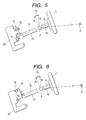
- Fig. 5 is a schematic diagram for explanation of a first embodiment.
- the shift control lever 2 extends toward the viewer of the diagram, that the guide pin 25 extends toward the back side of the diagram and that the guide plate 29 is provided on the back side of the diagram.
- the shift control lever starts to move from D position toward the upper side.
- the driver tends to operate the shift control lever 2 on a concentric circle about the rotational center of his or her shoulder. It is a most natural movement to the driver to operate the shift control lever 2 by virtue of the rotation of the shoulder without bending the arm.
- the rotational center of the shoulder of the driver of a "standard build" at his or her driving position is defined as a "shoulder point" P.
- a dummy JM50
- the "shoulder point” may be set individually with reference to the standard build of the people of a country to which motor vehicles are exported.
- the shift control lever 2 tends to be operated on a concentric circle about the shoulder point P, in other words, with a distance between the shoulder point P and the position of the shift control lever 2 being maintained constant.
- the shift shaft 22 rotates while being shifted from the shift control lever 2 side toward the guide plate 29 due to the shift of the shift control lever 2 toward the upper side (vector d1') accompanying the pull-up operation.
- the guide pin 25 is shifted from D position in the guide plate 29 as shown by a vector e1 when the shift control lever 2 is shifted axially.
- An axial component of this vector e1 i.e., an axial shift distance of the guide pin 25 corresponding to the shift distance A1 of the shift control lever 2 is denoted by reference character/numeral a1.
- the height of the step between N-R positions may be set in consideration of the driver's unintentional pull-up distance A1.
- the height of the step may be set higher than the shift distance in the axial direction S2 of the guide pin 25 which is shifted by the shift distance A1 of the shift control lever 2.
- a shaded step portion by diagonal lines is a portion additionally provided on the existing step portion to have a higher height from the aforesaid reason.
- a gear shift from D to R positions accompanied by a pull-up operation of the shift operation lever 2 can be completed by pulling up the shift control lever 2 a shift distance greater than the height of the step between N and R positions.
- the guide pin 25 having a substantially circular cross-section it is desirable to set the height of the step between N-R positions greater than a sum of the shift distance a1 and the radius of the circular cross-section of the guide pin 25 (similar in the following embodiments, too).
- An erroneous gear shift can be prevented from occurring further effectively by increasing the height of the step by a height corresponding to the radius of the circular cross-section of the guide pin 25. Namely, if the height of the step is higher than the shift distance a1 but lower than the sum of the shift distance a1 and the radius of the guide pin, the center of the cross-section of the guide pin 25 becomes higher than the height of the step.
- the steps in the guide plate 29 are set higher by taking into consideration the driver's operation tendency in operating the shift control lever 2 vertically.
- the step between N-R positions is formed higher than the shift distance of the guide pin 25 corresponding to the pull-up distance when the shift control lever 2 is operated vertically with the distance from the shoulder point P being maintained constant. This can effectively prevent the occurrence of an erroneous gear shift into R positions as a result of an unintentional pull-up operation of the shift control lever 2 when shifted from D position to N position.
- Fig. 6 is a schematic diagram for explanation of a second embodiment. From the same reason as that explained in the description of the first embodiment, an erroneous gear shift into R position may occurr when shifted from S position to N position.
- a vector d2 in Fig. 6 denotes a direction and a shift distance that are originally intended when the shift control lever 2 is shifted from S position toward P position.
- a vector d2' denotes a direction and a shift distance when the shift control lever 2 is rotated with the distance from the shoulder point being maintained the same.
- A2 is a shift distance, i.e., a pull-up distance generated in the direction of the axis S2 of the shift shaft 22 by virtue of a difference between those vectors d2, d2' .
- Reference character/numeral a2 is a shift distance in the direction of the axis S2 when the guide pin 25 is shifted as indicated by the vector e2.
- the guide pin 25 is shifted into R position.
- the step between D-S positions is formed lower and the step between N-R positions is formed higher, or the step of the former is formed lower, and the step for the latter is formed higher, whereby it is effective to set the step between S-R positions higher than the shift distance a2.
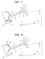
- Fig. 7 is a schematic diagram for explaining the third embodiment.
- the shift control lever 2 When shifted from P position to R position, the shift control lever 2 is operated to be shifted to a lower side after it is pulled up. To try to explain this through the movement of the guide pin 25, after it is shifted a shift distance greater than the height of the step between P-R positions in the direction S2 of the shift shaft 22, the guide pin 25 is shifted in a direction normal to the direction S2.
- the driver tends to pull up the shift control lever 2 in a direction d3, in other words, in a direction from the shift control lever 2 toward the shoulder point P. Since the movement of the guide pin 25 is restricted by the configuration of the guide plate 29, however, the shift control lever 2 is permitted to be shifted only in the direction S2. Therefore, the shift control lever 2 has to be shifted in the direction of the axis S2 of the shift shaft. When this direction is looked at from the driver side, the shift control lever is pulled up in a direction slightly upwardly of the direction d3 which makes the driver feel the most natural pull-up feeling, and therefore the permitted pull-up direction may make the driver feel an unnatural lever operation feeling.
- a portion of the step between P-R positions which is shaded with diagonal lines is cut.
- a direction of an edge portion of a sliding portion 70 which is newly formed by cutting the diagonally lined portion, or a direction of an edge portion along which the guide pin 25 is caused to slide while kept in abutment therewith is denoted by reference character/numeral de4.
- an acute angle is referred to as angle ⁇ 1 which is formed by the direction d4 of the edge portion (sliding direction) and a straight line L parallel with a straight line connecting the shift control lever 2 and the shoulder point P.
- an acute angle is referred to as angle ⁇ 2 which is formed by the axis S2 of the shift shaft 22 and the straight line L.
- the step is configured such that the angle ⁇ 1 with respect to the direction of the edge portion is smaller than the angle ⁇ 2 with respect to the axis S2 of the shift shaft. From the viewpoint of the shift feeling , it is preferable that the angle ⁇ 1 approximates as close to zero as possible, in other words, the sliding direction d4 and the straight line L are substantially parallel with each other.
- Fig. 8 is a schematic diagram for explaining a fourth embodiment. From the same reason as that explained in the third embodiment, even when shifting gears from D to S positions, there is probability that the driver will be feel an unnatural shift feeling. To cope with this, as shown in Fig. 8, a part of the step between D-S positions in the guide plate 29 is cut diagonally.
- indicated by reference character/numeral d5 is a direction of an edge portion of a sliding portion 80 where the guide pin 25 is shifted while kept in abutment therewith or a direction in which the guide pin 25 is shifted while kept in abutment the sliding portion 80.
- an acute angle is referred to as angle ⁇ 3 which is formed by the direction d4 of the edge portion (sliding direction) and a straight line L parallel with a straight line connecting the shift control lever 2 and the shoulder point P.
- an acute angle is referred to as angle ⁇ 4 which is formed by the axis S2 of the shift shaft 22 and the straight line L.
- the step is configured such that the angle ⁇ 3 with respect to the direction of the edge portion is smaller than the angle ⁇ 4 with respect to the axis S2 of the shift shaft.
- the angle ⁇ 1 approximates as close to zero as possible.
- the above first to fourth embodiments are combined with one another, by which the shift feeling in the respective gear shifts can be improved and the occurrence of erroneous gear shifts can further be prevented.
- the shift control device for a transmission mechanism has been described in which the shift of the shift control lever is regulated by means of the guide pin and the guide plate.
- the present invention is not limited to a shift control device constructed as described in those embodiments and it may be applied to a shift control device for a transmission mechanism which is constructed in another way.
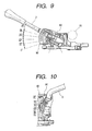
- embodiments will be described below in which the present invention is applied to the transmission mechanism shift control devices shown in Figs. 9 and 10.
- a shift control lever mounting shaft 90 is provided in the vicinity of the steering shaft 16, and the shift control lever 2 is mounted on this mounting shaft 90.
- a detent pawl 91 which is a flat plate-like guide member, is integrally provided on the shift control lever. This detent pawl 91 regulates the shift of the shift control lever 2 in conjunction with a detention body 92.
- the detent pawl 91 mounted on the shift control lever 2 plays a role of the guide pin in the transmission mechanism shift control device shown in Fig. 1, and the detention body 92 as a role of the guide plate in the same device.
- Fig. 11 is a schematic diagram explaining the fifth embodiment.
- An object of this embodiment is to prevent an erroneous gear shift when gears are shifted from D position (or 2 nd position) to R position, and the embodiment can be a modification of the first and second embodiments.
- the shift control lever is swung with the distance from the shoulder point being maintained equal or constant. This allows the shift control lever 2 to be pulled up and the detent pawl 91 to be shifted as indicated by a vector e4, a shift distance a3 being generated in a direction of the height of the step of the detention body 92. To cope with this, the height of the step between N-R positions is set greater than the shift distance a3 of the detent pawl 91.
- the detent pawl 91 is a flat plate, its area engaging the step of the detention body 92 is wide, and the pawl does not have any curved surface, and therefore no compensating means, such as those described in the first and second embodiments, needs to be provided (the height of the step is increased by a distance equal to the radius of the guide pin) .
- the step between 2-R positions may be set in the same manner as done in the second embodiment (the difference in height between the step between N-R positions and the step between D-R positions) .
- Fig. 12 is a schematic diagram for explaining a sixth embodiment.
- This embodiment is needed when the gears are shifted from P position to R position.
- An object of this embodiment is to improve the shift feeling when the shift control lever 2 is pulled up, and the embodiment may be regarded as a modification of the third and fourth embodiments.
- the driver tries to operate the shift control lever toward the shoulder point. This causes the detent pawl to be caught on a sliding portion of the step between P-R positions, and a direction in which the shift control lever can be pulled up is different from a direction which makes the driver feel no feeling of physical disorder.
- the detent pawl 91 is configured such that it is partially cut (a diagonally lined portion corresponds to a cut-away portion.
- the portion is diagonally cut in a linear, curved or parabolic fashion.
- This can provide the same effectiveness as those provided by the third and fourth embodiments.
- the specific conditions of those configurations are substantially the same as those described in the third and fourth embodiments, and therefore, a description thereof will be omitted here.
- the step between P-R positions, D-2 nd positions, or 2 nd -L positions on the detention body 92 side may be cut.
- the detention body side instead of the detent pawl side, the detention body side may be cut as described above, or both the detent pawl and detention body sides may be cut.
- Fig. 13 is a schematic diagram for explaining a seventh embodiment of a transmission mechanism shift control device.
- the transmission mechanism shift control device according to this embodiment is basically identical to the previously described ones in that the components shown in Figs. 1 and 2 are used therein but is different from those in the mounting of the transmission mechanism shift control device 15 relative to the steering shaft 14.
- the shift shaft 22 is mounted on the transmission mechanism shift control device 15 such that the axis S2 of the shift shaft is oriented in a direction different from that of the axis S1 of the steering shaft 16.
- This is effected by setting the shift control device such that an angle ⁇ 1 forming an acute angle by the axial direction S2 of the shift shaft 22 and a horizontal line is smaller than an angle ⁇ 2 forming an acute angle by the axial direction S1 of the steering shaft 16 and the horizontal line.
- it is constructed such that an angle ⁇ 3 forming an acute angle by a swinging direction d3 of the shift control lever 2 and a vertical line V is smaller than an angle ⁇ 4 forming a smallest acute angle by a straight line on the plane of the steering wheel 1 and the vertical line V.
- the shift control lever can be operated with the distance between the shift control lever 2 and the shoulder point P being maintained substantially constant.
- the driver is prevented from feeling a feeling of physical disorder or discomfort, whereby the shift feeling can further be improved.
- the seventh embodiment can be combined with the first to sixth embodiments. Namely, the axial direction S2 of the shift shaft 22 is offset from the axial direction S1 of the steering shaft 16 to some extent, and the steps of the regulating member for the guide plate or the like may be configured as described in the above embodiments.
- the height of the step may be made greater than the shift distance resulting when the shift control lever is shifted to be pulled up with the distance between the lever and the shoulder point being maintained substantially constant before or after gear shifting.
- the guide pin in a case where the guide pin is shifted along the sliding portion while kept in abutment therewith as a result of the shift control lever being operated so as to be pulled up, it may be constructed such that the angle forming an acute angle by the shift direction of the guide pin and the reference line is smaller than the angle forming an acute angle by the axial direction of the shift shaft and the reference line.
- the reference line is a line connecting the position of the shift control lever with the shoulder point of the driver at his or her driving position.
- the shift path of the guide member in which the guide member is shifted along the sliding portion while kept in abutment therewith when the shift control lever is operated to be pulled up is substantially parallel with the reference line.
- the shift feeling can further be improved and the occurrence of erroneous gear shifting can further be prevented by devising the configuration of the guide plate.
Landscapes
- Engineering & Computer Science (AREA)
- General Engineering & Computer Science (AREA)
- Mechanical Engineering (AREA)
- Chemical & Material Sciences (AREA)
- Combustion & Propulsion (AREA)
- Transportation (AREA)
- Arrangement Or Mounting Of Control Devices For Change-Speed Gearing (AREA)
- Control Of Transmission Device (AREA)
Applications Claiming Priority (3)
| Application Number | Priority Date | Filing Date | Title |
|---|---|---|---|
| JP10301605A JP2000108710A (ja) | 1998-10-07 | 1998-10-07 | 自動車用の変速機構操作装置 |
| JP30160598 | 1998-10-07 | ||
| EP99119175A EP0992713B1 (fr) | 1998-10-07 | 1999-10-06 | Dispositif de sélection pour boite de vitesses |
Related Parent Applications (1)
| Application Number | Title | Priority Date | Filing Date |
|---|---|---|---|
| EP99119175A Division EP0992713B1 (fr) | 1998-10-07 | 1999-10-06 | Dispositif de sélection pour boite de vitesses |
Publications (2)
| Publication Number | Publication Date |
|---|---|
| EP1241381A2 true EP1241381A2 (fr) | 2002-09-18 |
| EP1241381A3 EP1241381A3 (fr) | 2004-05-12 |
Family
ID=17898969
Family Applications (3)
| Application Number | Title | Priority Date | Filing Date |
|---|---|---|---|
| EP99119175A Expired - Lifetime EP0992713B1 (fr) | 1998-10-07 | 1999-10-06 | Dispositif de sélection pour boite de vitesses |
| EP02009241A Withdrawn EP1241382A3 (fr) | 1998-10-07 | 1999-10-06 | Dispositif de sélection pour boíte de vitesses |
| EP02009238A Withdrawn EP1241381A3 (fr) | 1998-10-07 | 1999-10-06 | Dispositif de sélection pour boíte de vitesses |
Family Applications Before (2)
| Application Number | Title | Priority Date | Filing Date |
|---|---|---|---|
| EP99119175A Expired - Lifetime EP0992713B1 (fr) | 1998-10-07 | 1999-10-06 | Dispositif de sélection pour boite de vitesses |
| EP02009241A Withdrawn EP1241382A3 (fr) | 1998-10-07 | 1999-10-06 | Dispositif de sélection pour boíte de vitesses |
Country Status (4)
| Country | Link |
|---|---|
| US (3) | US6532842B1 (fr) |
| EP (3) | EP0992713B1 (fr) |
| JP (1) | JP2000108710A (fr) |
| DE (1) | DE69908058T2 (fr) |
Families Citing this family (9)
| Publication number | Priority date | Publication date | Assignee | Title |
|---|---|---|---|---|
| DE10131433B4 (de) * | 2001-06-29 | 2010-09-09 | Daimler Ag | Schaltvorrichtung für ein Kraftfahrzeuggetriebe |
| GB0220495D0 (en) * | 2002-09-04 | 2002-10-09 | Ford Global Tech Inc | A motor vehicle and a selector mechanism therefor |
| JP2004161132A (ja) * | 2002-11-13 | 2004-06-10 | Kawasaki Heavy Ind Ltd | 不整地走行車の変速装置 |
| US7278510B1 (en) * | 2004-04-22 | 2007-10-09 | American Supercars And Prototypes, Llc | Shifting system for an automobile automatic transmission |
| JP4781650B2 (ja) * | 2004-09-17 | 2011-09-28 | 川崎重工業株式会社 | 車両のシフトレバー装置 |
| DE102013109333A1 (de) * | 2013-08-28 | 2015-03-05 | Dr. Ing. H.C. F. Porsche Aktiengesellschaft | Betätigungsvorrichtung |
| JP2016060326A (ja) * | 2014-09-17 | 2016-04-25 | 株式会社東海理化電機製作所 | シフト装置 |
| JP7409601B2 (ja) * | 2018-01-05 | 2024-01-09 | 株式会社東海理化電機製作所 | シフト装置 |
| CN114857252B (zh) * | 2022-05-06 | 2023-09-19 | 岚图汽车科技有限公司 | 一种集成整车灯光控制功能的怀挡电子换挡器和控制方法 |
Family Cites Families (19)
| Publication number | Priority date | Publication date | Assignee | Title |
|---|---|---|---|---|
| US1434993A (en) * | 1921-11-14 | 1922-11-07 | William G Dunn | Gear-shifting mechanism for motor vehicles |
| US1906262A (en) * | 1932-12-14 | 1933-05-02 | Robert W Fischer | Gear shifting device |
| US2188403A (en) * | 1936-10-24 | 1940-01-30 | Frank D Frisby | Variable speed transmission mechanism for automobiles and the like |
| US2168592A (en) * | 1938-02-07 | 1939-08-08 | Vanderveld Anthony | Gear shifting mechanism |
| US2198681A (en) * | 1938-04-27 | 1940-04-30 | Chrysler Corp | Control for power transmission mechanism |
| US2169034A (en) * | 1939-01-23 | 1939-08-08 | Vanderveld Anthony | Gear shifting mechanism |
| US3264895A (en) * | 1963-05-08 | 1966-08-09 | Gen Motors Corp | Control linkage |
| FR1563876A (fr) * | 1968-02-09 | 1969-04-18 | Renault | |
| CH495442A (de) * | 1969-02-19 | 1970-08-31 | Rueti Ag Maschf | Eintragsorgan zum Eintragen von Schussfäden |
| US3575062A (en) * | 1970-01-08 | 1971-04-13 | Ford Motor Co | Transmission shift control linkage |
| US3646828A (en) * | 1970-10-21 | 1972-03-07 | Gen Motors Corp | Transmission controls |
| US3648828A (en) | 1970-12-31 | 1972-03-14 | Horace Mccaffrey Jr | Vibratory conveyor |
| US4762015A (en) * | 1985-10-31 | 1988-08-09 | Mazda Motor Corporation | Tiltable vehicle steering column assembly |
| US5099720A (en) * | 1987-02-26 | 1992-03-31 | Zahnradfabrik Friedrichshafen Ag | Control mechanism for an automatic gear-shifting transmission using turn signal control unit |
| JP2900363B2 (ja) * | 1987-11-09 | 1999-06-02 | トヨタ自動車株式会社 | 自動変速機用シフトレバー装置 |
| JPH05198117A (ja) | 1992-01-17 | 1993-08-06 | Sony Corp | 磁気ヘッド装置の製造方法 |
| JPH05196117A (ja) * | 1992-01-17 | 1993-08-06 | Toyota Motor Corp | 自動変速機のチェンジ機構 |
| US5289732A (en) * | 1992-12-24 | 1994-03-01 | Chrysler Corporation | Column-mounted shift control assembly |
| JPH10301605A (ja) | 1997-04-25 | 1998-11-13 | Sharp Corp | プログラマブルコントローラ |
-
1998
- 1998-10-07 JP JP10301605A patent/JP2000108710A/ja not_active Withdrawn
-
1999
- 1999-10-06 EP EP99119175A patent/EP0992713B1/fr not_active Expired - Lifetime
- 1999-10-06 DE DE69908058T patent/DE69908058T2/de not_active Expired - Fee Related
- 1999-10-06 EP EP02009241A patent/EP1241382A3/fr not_active Withdrawn
- 1999-10-06 EP EP02009238A patent/EP1241381A3/fr not_active Withdrawn
- 1999-10-07 US US09/413,877 patent/US6532842B1/en not_active Expired - Fee Related
-
2003
- 2003-01-22 US US10/348,741 patent/US6904825B2/en not_active Expired - Fee Related
- 2003-01-22 US US10/348,674 patent/US6829960B2/en not_active Expired - Fee Related
Non-Patent Citations (1)
| Title |
|---|
| None |
Also Published As
| Publication number | Publication date |
|---|---|
| DE69908058T2 (de) | 2003-12-04 |
| EP0992713A1 (fr) | 2000-04-12 |
| EP0992713B1 (fr) | 2003-05-21 |
| US20030106388A1 (en) | 2003-06-12 |
| EP1241382A2 (fr) | 2002-09-18 |
| JP2000108710A (ja) | 2000-04-18 |
| EP1241381A3 (fr) | 2004-05-12 |
| DE69908058D1 (de) | 2003-06-26 |
| US6904825B2 (en) | 2005-06-14 |
| US6829960B2 (en) | 2004-12-14 |
| US20030106389A1 (en) | 2003-06-12 |
| EP1241382A3 (fr) | 2004-05-12 |
| US6532842B1 (en) | 2003-03-18 |
Similar Documents
| Publication | Publication Date | Title |
|---|---|---|
| US4537088A (en) | Column shift type gear selector device for an automatic power transmission of an automotive vehicle | |
| US4245521A (en) | Manual transmission shifter for operating a transmission with flexible cables | |
| EP2172674B1 (fr) | Ensemble de contrôle de transmission doté d'un mécanisme de verrouillage | |
| US6532842B1 (en) | Shift control device for a transmission mechanism | |
| EP0978669B1 (fr) | Dispositif de commande à deux modes pour transmission automatique | |
| EP0622572A1 (fr) | Dispositif indicateur de position de rapport de vitesse du dispositif de commande dans une transmission automatique | |
| US5588934A (en) | Shifter with means for actuating cable to key mechanism | |
| USRE31451E (en) | Manual transmission shifter for operating a transmission with elongated actuators such as flexible cables | |
| GB2287076A (en) | Gear change device inhibits reverse selection and is separate from the gearbox | |
| US6622583B2 (en) | Automatic transmission shifter lever and transfer case shifter lever interlock mechanism | |
| KR100461377B1 (ko) | 자동 변속기의 시프트 록 장치 | |
| US20050217404A1 (en) | Selector apparatus of an automatic transmission of vehicle | |
| US8360194B2 (en) | Transfer box for transferring gearshifting movements in a vehicle | |
| US20050217403A1 (en) | Selector apparatus of an automatic transmission of vehicle | |
| JP4088050B2 (ja) | 車両用シフトレバー装置 | |
| JP3446246B2 (ja) | 自動変速機を備えた車両のシフトロック装置 | |
| JP2876089B2 (ja) | 車両用自動変速機の手動選速機構付シフト装置 | |
| JPH0219656Y2 (fr) | ||
| JP4599850B2 (ja) | 車両用自動変速機のシフト操作装置 | |
| KR200152215Y1 (ko) | 가변 레버비에 의한 차량용 변속 레버장치 | |
| KR100428154B1 (ko) | 자동변속기의 시프트 록장치 | |
| JPH05423Y2 (fr) | ||
| JPH09152022A (ja) | チェンジレバーのシフトパターン変換装置 | |
| JP3798505B2 (ja) | 手動変速機のリバースミスシフト防止機構 | |
| JPH09263153A (ja) | 自動車の自動変速機のシフト装置 |
Legal Events
| Date | Code | Title | Description |
|---|---|---|---|
| PUAI | Public reference made under article 153(3) epc to a published international application that has entered the european phase |
Free format text: ORIGINAL CODE: 0009012 |
|
| AC | Divisional application: reference to earlier application |
Ref document number: 992713 Country of ref document: EP |
|
| AK | Designated contracting states |
Kind code of ref document: A2 Designated state(s): DE GB |
|
| PUAL | Search report despatched |
Free format text: ORIGINAL CODE: 0009013 |
|
| AK | Designated contracting states |
Kind code of ref document: A3 Designated state(s): DE GB |
|
| 17P | Request for examination filed |
Effective date: 20040716 |
|
| 17Q | First examination report despatched |
Effective date: 20040916 |
|
| AKX | Designation fees paid |
Designated state(s): DE GB |
|
| GRAP | Despatch of communication of intention to grant a patent |
Free format text: ORIGINAL CODE: EPIDOSNIGR1 |
|
| STAA | Information on the status of an ep patent application or granted ep patent |
Free format text: STATUS: THE APPLICATION IS DEEMED TO BE WITHDRAWN |
|
| 18D | Application deemed to be withdrawn |
Effective date: 20060120 |