EP1241865A2 - Méthode de fabrication de masque, dispositif de production d'image et support d'enregistrement lisible par ordinateur - Google Patents
Méthode de fabrication de masque, dispositif de production d'image et support d'enregistrement lisible par ordinateur Download PDFInfo
- Publication number
- EP1241865A2 EP1241865A2 EP02005346A EP02005346A EP1241865A2 EP 1241865 A2 EP1241865 A2 EP 1241865A2 EP 02005346 A EP02005346 A EP 02005346A EP 02005346 A EP02005346 A EP 02005346A EP 1241865 A2 EP1241865 A2 EP 1241865A2
- Authority
- EP
- European Patent Office
- Prior art keywords
- gray scale
- dot
- mask
- scale levels
- dot patterns
- Prior art date
- Legal status (The legal status is an assumption and is not a legal conclusion. Google has not performed a legal analysis and makes no representation as to the accuracy of the status listed.)
- Granted
Links
Images





Classifications
-
- H—ELECTRICITY
- H04—ELECTRIC COMMUNICATION TECHNIQUE
- H04N—PICTORIAL COMMUNICATION, e.g. TELEVISION
- H04N1/00—Scanning, transmission or reproduction of documents or the like, e.g. facsimile transmission; Details thereof
- H04N1/40—Picture signal circuits
- H04N1/405—Halftoning, i.e. converting the picture signal of a continuous-tone original into a corresponding signal showing only two levels
- H04N1/4051—Halftoning, i.e. converting the picture signal of a continuous-tone original into a corresponding signal showing only two levels producing a dispersed dots halftone pattern, the dots having substantially the same size
Definitions
- the present invention relates to a mask producing method, an image outputting device and computer readable recording medium, in particular, to a mask producing method for producing a mask of a threshold matrix by which a halftone-dot image is created with an image quality improved, the threshold matrix being used for generation of halftone image in digital image processing, and, to a so-called FM mask, a type of the threshold matrix, attracting attention in terms both of processing speed and image quality, an image outputting device, and a computer readable recording medium storing a software program, and mask data, thereof.
- a method of producing a halftone image in digital image processing i.e., a method of expressing a shade or gray scale of an image by a combination of on-dot (for example, black dot) and off-dot (for example, white dot), there are "dithering” and "error dispersion method", and they have the following characteristics, respectively.
- Dithering is a method of converting original multi-level image data into a corresponding dot pattern using a threshold matrix (referred to as a "dither matrix” , or, simply, “mask”, hereinafter) produced based on a specific rule, by comparing with the original multi-level image data every pixel.
- a threshold matrix referred to as a "dither matrix” , or, simply, “mask”, hereinafter
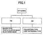
- FIG. 1 shows a type of dithering.
- dithering expresses a gray scale by changing the density of on-dots, and includes a frequency modulation scheme (FM mask) dithering and an area modulation scheme (AM mask) dithering.
- FM mask frequency modulation scheme
- AM mask area modulation scheme
- on-dot density should express information in depth direction (8 bits) of the original image data has, on plane coordinates.
- the characteristics such as on-dot (for example, black dot) density and gray scale of the output image
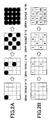
- the number of on-dots present within a predetermined area should be determined for every gray scale level, necessarily, as shown in FIG. 2A, for example.
- the above-mentioned dither matrix is produced as a result of on-dot arrangements being summarized in a table on a predetermined area for respective gray scale levels, while matching is held with regard to the order of on-dot occurrence along gray scale before and after a relevant gray scale level, as shown in FIG. 2B.
- FIG. 2A shows on-dot arrangement determined for each gray scale level
- FIG. 2B shows a process of producing a dither matrix according to the on-dot arrangements shown in FIG. 2A.
- the control of the order of on-dot occurrence along the gray scale is made for preventing that a difference in dot pattern in the meantime may be recognized in an output image as a stepwise manner, at a time a dither matrix, to be applied is switched on an image in which gray scale changes gradually.
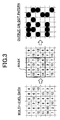
- a dither matrix Although it is possible as a dither matrix to apply a matrix having a size the same as that of an input original image theoretically, since a memory capacity needed would become huge, it is common to apply a dither matrix of size much smaller than an original image, while repeatedly shifting it a position, area by area, in a manner of tile placement, on an original image, as shown in FIG. 3, so as to perform conversion to a halftone dot pattern.
- this scheme may be applied to an image requiring a medium (not very high) image quality.
- this scheme generally, it is noted that a measure should be taken against Moiré.
- the error dispersion method may be applied to an image requiring a high or very high image quality.
- this scheme requires relatively high cost on the other hand.
- any schemes have particular merits and demerits, as for dithering and error dispersion schemes, it is common to properly select one of them according to a nature of an image output uniting applied or a type of image to be processed.
- FM mask method FM screen method
- blue noise mask method a scheme having features including merits of these two types of schemes.
- this scheme is called "FM mask method”, “FM screen method” or “blue noise mask method”, and is similar to a Bayer-type method which is a type of "dithering", and employs a way of the same frequency modulation type (FM) mask comparing method.
- a threshold matrix is applied which is determined in consideration of frequency characteristic (blue noise characteristic, or BN characteristic) only concerning high frequency component except low frequency component in case of threshold determination.
- frequency characteristic blue noise characteristic, or BN characteristic
- it is a mask comparing method it is possible to prevent periodicity in low frequency from being conspicuous as in case of Bayer-type method or dot-collection type dithering, and, also, to prevent generation of Moiré, as a result, the resolution characteristic as superior as that in case of application of the error diffusion method can be acquired. Therefore, this method attracts attentions from various fields, i.e., a printing field, and so forth, and various approaches are tried thereon.
- a method (referred to as a 'void and cluster method or scheme', hereinafter) is disclosed of comparing a void (image region having coarse on-dots) and a cluster (image region having dense on-dots), and exchanging on-dots therebetween, thereby, performing mask optimization.
- a random element can be eliminated as a result of a dot pattern used as a starting point being arbitrarily controllable, and thereby, recursion of a calculation result can be secured. Furthermore, calculation time can be shortened while the quality of the mask finally produced can be improved as a result of a uniform distribution being able to be applied at an initial stage.
- this method is a so-called 'sequential method' in which, from such a starting dot pattern, optimization is performed step by step along gray scale, a dot arrangement is thus necessarily restricted by an immediately precedingly determined dot pattern.
- the starting dot pattern is ideal in terms of avoiding graininess and/or texture characteristic, it is a feature being held only at a starting point, and, after adding on-dots thereto so as to produce a dot pattern in a subsequent gray scale level, this feature may be degraded. Then, after repeating this process for producing dot patterns for the subsequent gray scale levels, so as to build a final FM mask, difference from the starting point is accumulated gradually, and, accordingly, the final FM mask may be far different from the ideal one.
- the present invention has been devised for the purpose of solving the above-mentioned problem, and, an object of the present invention is to provide a halftone conversion mask such as an FM mask through a comparatively simple configuration while having an ability to maintain the quality of dot arrangement in all gray scale levels.
- the dot pattern which do in this way i.e., the independent optimization has been made for every gray scale pick up as mentioned above
- the optimization processing which needs high-precise calculations should be made only for the pick-up gray scale levels, and, thus, it is possible to effectively reduce the total processing time.
- the difference between the optimized dot patterns is cancelled gradually as mentioned above, the continuity of the halftone pattern along the gray scale can be secured, and it becomes possible to produce a mask with more good quality.
- a dot pattern including an on-dot which is not turned on in any of the dot patterns of both ends of the relevant gray scale section at a time of the difference cancellation between the above-mentioned optimized dot patterns. Consequently, it is possible to raise mask quality also for the intermediate gray scale level by utilizing a dot pattern not completely depending on the first determined dot pattern.
- the minimum interval between the gray scale levels chosen first as mentioned above it is preferable to set it as being not narrower than 1/32 the total number of gray scale levels. Consequently, it is possible to effectively shorten the total processing time, and, also, to cause disconnection of continuity which otherwise would occur due to setting shorter intervals provided between the individually optimized dot patterns.
- the interval of the above-mentioned gray scale levels for which optimization is performed first it is preferable to change the interval of the above-mentioned gray scale levels for which optimization is performed first, according to image regions, such as a highlight region, an intermediate region, and a shadow region. Consequently, for example, for a region in which change in gray scale is not noticeable, or a region for which a specific texture tends to occur by optimization, a large interval may be set between the gray scale levels chosen first and thus operation time may be shortened. Also, it is possible to control generation of texture by performing the interpolation processing in the meantime.
- a dot pattern obtained by usual halftone processing of Bayer-type dithering. etc. may be adopted for the gray scale levels chosen first. Consequently, it is possible to shorten the operation time concerning mask production. Moreover, in case a dot pattern obtainable by applying conventional halftone processing serves as a more suitable dot arrangement, it becomes possible to perform the conventional halftone processing to produce a mask for a short time.
- the dot pattern by the above-mentioned conventional halftone processing is determined for the gray scale levels chosen first, it is possible to adopt a dot pattern obtained by the same conventional halftone processing, and thus, to produce a mask also for each gray scale level inserted between the gray scale levels first processed. Consequently, it is possible to positively shorten the operation time, and secure the continuity between gray scale levels. Furthermore, it is possible to apply a same type of dot pattern for a plurality of gray scale levels so as to reduce the number of total dot patterns and to shorten mask production time.
- the mask pattern by the above-mentioned conventional halftone processing is adopted and a mask is thus produced
- halftone processing scheme applied there according to an image mode applied in the image outputting unit at a time of outputting the image processed by the halftone processing concerned using the mask concerned.
- the most suitable scheme may thus be applied.
- determination of the above-mentioned dot pattern includes processing which evaluates distance between on-dots in the dot pattern, and, it is preferable to perform the evaluation with a weight in particular on a specific direction.
- the weight applied is gradually reduced from the central direction. Therefore, a possibility of occurrence of a blank portion in a certain specific part can be avoided.
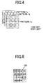
- FIG. 4 shows an example of configuration of a halftone conversion mask (namely, a threshold matrix as described above) 1 produced by a mask producing method in a first embodiment of the present invention, where dot patterns 1a, 1b and 1c on respective gray scale levels a, b and c are produced independently. Consequently, it is possible to remove the above-mentioned accumulation of errors or restrictions as compared with a case a mask is produced through the sequential method.
- a halftone conversion mask namely, a threshold matrix as described above
- a halftone conversion mask such as that shown in FIG. 5 is adopted in terms of limited performance of CPU, memory, operation system (OS), and so forth for the purpose of price reduction.
- Such a mask 100 covers all of dot arrangement patterns in respective gray scale levels in one mask, and each square corresponds to 1 dot.
- This mask is applied for every portion of an input image, and pixel value comparison is carried out for every dot each time. Then, if the pixel value of the input image is higher, it is converted into an on-dot, while, if lower, it is converted into an off-dot. By applying this operation repeatedly to the whole area of the input image, it is possible to convert the whole input image into a corresponding halftone image (see also FIG. 3).
- a threshold mask such as that shown in FIG. 5, based on dot patterns on respective gray scale levels, as those shown in FIG. 4, in a manner described above with reference to FIGS. 2A and 2B. That is, it may also be said that the above-described method of preparing dot patterns on respective gray scale levels is one method for obtaining a threshold mask such as that shown in FIG. 5.
- Another form of an FM mask (a set of dot patterns) in the first embodiment of the present invention is produced in a basic production procedure described below. That is, first, as shown in FIG. 6, a plurality of gray scale levels which are not adjacent together are chosen (m and n in FIG. 6) and, then, as shown in FIGS. 7A and 7B, for the thus-selected gray scale levels m and n, the optimum dot patterns are generated individually, respectively.
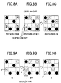
- a black circle ⁇ denotes an on-dot common between the gray scale levels n and m (referred to as a common dots, hereinafter); white circle ⁇ denotes an on-dot different therebetween (referred to as a different dot, hereinafter), and a squire having no circle denotes an off-dot.
- the above-mentioned common dots and difference dots of the optimum dot patterns are sorted out, and, then, along the number of gray scale levels present between these optimum patterns m and n, as shown in FIG. 8B, a dot pattern present in the gray scale section m through n is produced by canceling the above-mentioned different dots one by one.
- Such processing is performed over the whole gray scale. That is, the whole gray scale range is divided into a plurality of sections, and a dot pattern on the gray scale level in each dividing point is independently determined first as an optimum dot pattern for the gray scale level. As to dot patterns on the gray scale levels present between these dividing points, they are then produced one by one based on the previously optimized dot patterns on the gray scale levels at the both ends of the relevant section, i.e., the dot pattern on the gray scale level at the dividing points. Consequently, a suitable halftone conversion mask, i.e., a set of dot patterns for the respective gray scale levels can be obtained.
- various methods may be applied therefor, for example, the above-mentioned void and the cluster method, blue noise filter using method disclosed by the above-mentioned Japanese patent No. 2622429, or another method applying any of evaluation functions proposed so far.
- the difference in gray scale level, i.e., the pitch (m-n) between the pick-up dividing points should not be necessarily fixed. It is possible to aim at shortening of processing time by widening this pitch as for such a shadow part as that in which the influence of dot arrangement is not likely to be conspicuous. Moreover, when this pitch is conversely made too narrow, change in dot arrangement between the gray scale levels at the dividing points may become noticeable, and it may become a problem in respect of the continuity of gray scale in an output image.
- an interval wider than the interval corresponding to a number of gray scale levels 1/32 of the total number of gray scale levels, or an interval corresponding to a number of gray scale levels approximately 1/16 of the total number of gray scale levels of gray scale levels should be set so that the quality on the continuity of gray scale is securable.
- FIGS. 9A through 11F A specific scheme of the interpolation processing for gray scale levels present between the above-mentioned dividing points will now be described with reference to FIGS. 9A through 11F.
- various methods can be considered according to how the balance between processing time (operation time) and mask quality is determined.
- a scheme will now be described based on FIGS. 9A through 9C.
- the portion enclosed by the circle in FIG. 9B is a portion in which a different dot 'a' on the dot pattern of the gray scale level m and a different dot 'b' on the dot pattern of the gray scale level n are adjacent to one another.
- these different dots may be called near different dots.
- ON/OFF of these contiguity dots are replaced in the pattern of the gray scale level m+1 shown in FIG. 9B.
- a broken circle shows the different dot position on the dot pattern of the gray scale level 'n'.
- the following methods may be considered as methods rather in consideration of importance on mask quality. That is, such a combination of different dots is selected that, calculation of a specific evaluation function is performed on the dot pattern obtained by dot exchange between the different dot pair in the relevant combination, and the evaluation result become the best among the other possible combinations.
- This scheme of applying evaluation of dot pattern by using the specific evaluation function is effective, because, otherwise, according to the method mentioned above such as to give a priority on reduction of processing speed, an undesirable dot density change, a texture caused by an ordering matrix used for selecting the different dot pair, or the like may occur.
- any of the evaluation functions proposed for producing the satisfactory FM mask described above in the description of the method of producing optimum dot pattern on the gray scale level of each dividing point may also be applied.
- functions representing VTF (approximation of human visuality characteristics) and equal direction characteristics (two-dimensional uniformity in dot arrangement) such as those below may be used:
- Evaluation Value ⁇ ⁇ 2D_FFT [Bit_map (x, y)] 2 ⁇ VTF (x, y) where:
- VTF the function which approximates such human visuality characteristics
- a dot position indicated by a star mark in these figures, and is not included in any of the dot patterns on the gray scale levels n and m at the dividing points, is used as a dot position which is temporarily turned on as the above-mentioned hollow on-dot in a dot pattern present intermediately in the relevant section.
- this hollow on-dot is an on-dot which can exist only in the interpolation processing section, and therefor, should be deleted before reaching the other end of the relevant section during the process of producing dot patterns present in the relevant section. In this viewpoint, it is not preferable to provide many hollow on-dots, or to use the hollow on-dots continuously for a relatively large number of intermediate gray scale levels.
- FIGS. 11A, 11B, 11C and 11D illustrate the scheme same as that described above with reference to FIGS. 9A through 9C, while FIGS. 11A, 11E, 11F and 11D illustrate the above-mentioned scheme of using the hollow on-dot.
- each black circle represents a common dot present in both the dot patterns of the gray scale levels m and n;
- each oblique-hatched circle represents a different dot only present in the dot pattern of gray scale level m;
- each vertical hatched circle represents a different dot only present in the dot pattern of the gray scale level n;
- the star mark represent the hollow on-dot.
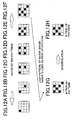
- the halftone conversion mask i.e., a relevant set of dot patterns, between the gray scale levels m through n thus produced may be combined with a halftone conversion mask of other gray scale level range produced by another halftone processing scheme of the conventional type as shown in FIGS. 12A through 12H. That is, it is possible, by using the scheme of generation of the optimum pattern of the dividing point and generation of the pattern by the interpolation processing on an intermediate portion described above, to also combine the above-described mask producing method with a different halftone processing scheme.
- FM mask can provide a high definition halftone image by adopting a dot arrangement obtained by the error diffusion scheme as the dot pattern of the dividing point.
- a periodic dot arrangement may provide a desirable impression by the Bayer-type scheme rather than such an error-diffusion-type dot arrangement. Such a tendency can be seen especially on a graph image used frequently in business documents.
- a halftone conversion mask is produced according to the Bayer-type scheme for a gray scale range in which dot arrangements according to the Bayer-type scheme give more satisfactory impression.
- the gray scale levels at both ends of the gray scale range to which the Bayer-type scheme has been applied are regarded as those at the pick-up dividing points according to the first embodiment of the present invention, and, also, further dividing points are pick up on the outsides of this Bayer-type-scheme applied gray scale range.
- the dot patterns in the intermediate portions between these dividing points outside of the Bayer-type-scheme applied gray scale range are determined according to the interpolation processing according to the first embodiment of the present invention.
- a specific halftone processing should be applied depending on an image outputting unit to be applied so as to provide a stable output image. That is, in the image outputting unit with an engine of an electro-photographic type or a thermal transfer type, dot reproducibility in high resolution tends to become unstable. Accordingly, a dot-collection-type dithering is preferably used.
- this combining scheme also be applied to a combination between a plurality of FM masks of different types.
- FM mask produced according to the conventional sequential method may be combined with FM mask produced according to the first embodiment of the present invention in case gray scale continuity should be more positively secured.
- any FM mask suitable to the gray scale and resolution characteristic of an image mode applied in the image outputting unit can be easily built by using the halftone conversion mask producing method in the first embodiment of this invention.
- a dot arrangement obtained through the conventional scheme can be used as a dot pattern on the pick-up gray scale level, i.e., the dividing-point gray scale level, as mentioned above.
- shortening of processing time and reduction of the number of dot patterns for finally forming the FM mask are possible by applying such a conventional method for a specific gray scale range.
- FM mask produced according to the first embodiment of the present invention may be applied to an image outputting unit, such as an electro-photographic type, thermal transfer type, or ink-jet type, which provides halftone-dot image. It is possible to store the data of the FM mask into a recording medium of exclusive use, such as a ROM/non-volatile RAM, and to install it in an image outputting unit concerned as a form of an image-processing module. Alternatively, data of the FM mask produced according to the first embodiment of the present invention may be stored into another type of recording medium, such as FD (floppy disk), CD (compact disc), DVD (digital video disk), and a memory card, as a program for printer control, and may then be installed in a computer.
- FD floppy disk
- CD compact disc
- DVD digital video disk
- a memory card as a program for printer control
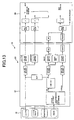
- a printer driver (application software) 21 installed in the computer 20 performs processing of color matching of image processing to image data output from an intermediate module (GDI) 40 of image drawing processing on the OS (operating system) of a computer 20. Then, the remaining processing which includes the halftone processing according to the first embodiment of the present invention is performed by a processing module installed in the printer 30.
- GDI intermediate module
- image processing is divided and is performed by the computer 20 and printer 30 separately in the case shown in FIG. 13, the computer 20 in recent years is developed greatly, and, thereby, in case processing can be achieved at high speed by utilizing software program completely including the necessary processing steps, all the image processing including processing according to the first embodiment of the present invention may be performed by the computer 20.
- the above-mentioned void and cluster scheme is used in many cases. That is, according to the method which uses Fourier transform, since the frequency characteristic of a mask itself is finely adjusted, good FM mask in terms of graininess can be produced by considering human visuality characteristic, etc. However, a large amount of operation processing is needed, and unpractical operation time may be needed depending on a mask size in the Fourier transform scheme.
- output image quality may be inferior to FM mask by the Fourier transform method in respect of the quality of the halftone conversion mask thus obtained, while merely small amount of operation processing is needed as mentioned above.
- the void and cluster scheme since optimization is performed by only dot exchange between void part and cluster part as mentioned above, a texture resulting from dot arrangement cannot be removed effectively. Consequently, the quality of FM mask finally formed is greatly influenced by the dot pattern at an initial state. Consequently, mask quality may be unable to be guaranteed completely there.
- a white noise pattern is used as the initial dot pattern.
- good FM mask is not necessarily produced by the above-mentioned void and the cluster scheme by the reason mentioned above. That is, when the quality of the white noise pattern is bad, then, before arriving at the optimum dot arrangement, a situation where only an inferior dot pattern in which merely a dot interval is uniform but texture remains may occur.
- FM mask obtained by the method using the above-mentioned error diffusion processing pattern as the initial pattern may have a texture which is still conspicuous, and quality is low in many cases. It originates in that distortion must be circulated in the mask for several pixels according to a mask applying method such as that of the Fourier transform scheme, while, according to the error diffusion scheme, distortion is diffused outside, and adjustment is made for dot interval and dot arrangement with respect to an entire image.
- a problematic one here is a dot arrangement with uniform dot intervals occurring near an edge of the mask due to the above-mentioned "swept-together” effect. That is, in case on-dots are arranged in the mark edge part with somewhat uniform on-dot intervals, this regularity cannot be removed by the above-mentioned void and cluster scheme, and, finally, a texture which emphasizes mask edge may occur.
- the present invention also takes into consideration on this point, and aims at improvement in FM mask quality while maintaining an effect of reduction in amount of operation processing on the void and cluster scheme in a second embodiment of the present invention which will now be described.
- FIG. 14A shows a halftone dot pattern obtained when error diffusion processing is performed on a gray-scale-fixed-area part at a certain gray scale level.
- the above-mentioned "swept-together" effect has occurred in which occurrence of on-dots is reduced until error is accumulated to some extent, as a problem inherent to the error diffusion scheme. Occurrence of such a blank part due to the "swept-together” effect may be a series problem in case of applying the error diffusion scheme.
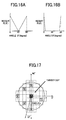
- this correction term R ( ⁇ ) is made into a function in which a large angle range is covered toward 45° which is the middle from each of the angles 0° and 90°, and, through this range, the weight R( ⁇ ) changes gradually, as shown in FIG. 16A.
- the correction term R( ⁇ ) is set as a function in which the weight is applied and changes only for a narrow range around each of 0° and 90°, as shown in FIG. 16B. Further, for the ranges other than those, no correction is made by the correction term R( ⁇ ), and evaluation merely according to the relative distance is performed regardless of the directional factor there.
- the on-dots 2 ⁇ , 5 ⁇ present in the vertical/horizontal direction and the on-dot 1 ⁇ present within the above-mentioned angle range of ⁇ 16° from each of the vertical and horizontal directions have the weight by the correction term R( ⁇ ) applied thereto, and, thus, have the formula (2) applied thereto.
- the weight applied is heavy on the dot 2 ⁇ and 5 ⁇ while it is light on the dot 1 ⁇ .
- R ( ⁇ ) has been described as a function varying linearly with reference to FIGS. 16A and 16B, this R( ⁇ ) may not be limited to a linear function, but may be an n-th function (n ⁇ 1). However, in a case of a function having a fixed value through a range near 0° or 90° were applied, an unnecessary blank zone may occur there. In order to prevent generation of such a situation, as shown in FIGS. 16A and 16B, it is necessary to set the weight as a function by which the weight positively decreases gradually from 0° or 90°.
- an optimum margin of angle ⁇ is determined as an angle range such as to cover a search range of two dots, as shown in the figure, i.e., ⁇ 8°. If the margin were determined less than this, it would not be possible to detect an alignment of on-dots around 0° or 90° in the 8 ⁇ 8 mask.
- the upper limit of the margin such a range as that an oblique direction less than ⁇ 45° should not be emphasized. Accordingly, assuming the same size of mask of 8 ⁇ 8, it is reasonable to set the upper limit as the search range for three dots d1 through d3 with respect to the target dot D, shown in FIG. 18, i.e., ⁇ 16°. In case of applying ⁇ 16° as the margin, the margin is total 32° which may not be regarded as vertical nor horizontal direction. However, in the 8 ⁇ 8 mask, and in case ⁇ 8° is set as the lower limit as mentioned above, it is reasonable to set ⁇ 16° as the upper limit obtained by adding ⁇ 1 dot to the lower limit in search range.
- the reason why the 8 ⁇ 8 mask is assumed is that, as minimum 64 gray scale levels are needed for providing a predetermined image quality, and, in order to reproduce minimum 64 gray scale levels, the 8 ⁇ 8 mask size is needed.
- FIG. 19 shows an FM mask production flow according to the second embodiment of the present invention described above. This operation flow includes processing of determining as to whether all possible combinations of on-dots have been processed/tried, although not shown in the figure.
- Step S1 error diffusion processing is carried out for a predetermined gray scale level, and a dot pattern on the relevant gray scale level is produced. Subsequently, at Step S2, any on-dot A is chosen as a target dot. Then, in Step S3, another on-dot B is also chosen. Next, in Step S4, the on-dot B is turned off, and any off-dot C is newly turned on.
- Step S5 from the on-dot A, the angle ⁇ to any other on-dot in the periphery is calculated, and it is determined whether this angle ⁇ is within the range ⁇ 16° of 0° or 90° in Step S6.
- Step S7 the relative distance between the on-dot A and the relevant periphery on-dot is calculated by the above-mentioned formula (1).
- the determination result in Step S6 is Yes, the relative distance between the on-dot A and the relevant periphery on-dot is calculated by the above-mentioned formula (2) in Step S8.
- Step S9 it is determined whether the process in the Steps S5 through S7/S8 has finished for all the periphery on-dots after the operation of Steps S7 and S8. When the result of this determination is No, it returns to Step S5 and the same processing is performed on another periphery on-dot, and processing of Steps S6 and S7/S8 is repeated until the result of Step S9 becomes Yes.
- Step S9 When the determination result on Step S9 becomes Yes, subsequently the sum of the relative distances obtained at Steps S7/S8 are calculated in Step S10, and it is determined whether the value became the maximum. When the result of the determination is No, it returns to Step S2.
- determination on Step S10 becomes Yes, the current processing is finished after predetermined processing, as determining that the optimization has been completed.
- Steps S2 through S9 are repeated for all the combinations of the on-dot A and newly on-dot C, and, after that, a combination thereof such that the maximum result is obtained is selected as the optimized dot pattern.
- each of the above-mentioned formulas (1) and (2) has a smaller value as the relative distance becomes larger. Accordingly, if the calculation value obtained at Step S7/S8 is the calculation result of the formula itself, Step S10 determines whether or not the sum thereof is the minimum, and, when it is the minimum, the optimization is completed.
- the optimum dot pattern on the predetermined gray scale level obtained by the optimization processing according to the second embodiment of the present invention corresponds to each dot pattern 1a, 1b, and 1c shown in FIG. 4, or the dot pattern on the gray scale level m or n shown in FIG. 6, mentioned above in the description of the first embodiment of the present invention. Accordingly, the above-mentioned interpolation processing described with reference to FIGS. 7A through 11F is performed to produce dot patterns on the gray scale levels present between the gray scale levels at the pick-up dividing points based on the thus-obtained optimum dot patterns. As a result, the halftone conversion mask (FM mask) such as that shown in FIG. 5 can be derived.
- FM mask halftone conversion mask
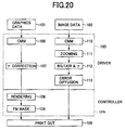
- FIG. 20 shows an example of a printer controller employing an FM mask obtained according to any of the above-mentioned first and second embodiments of the present invention.
- 101 denotes graphic data and 102 denotes image data.
- CMM processing 106 and 110 is performed on the graphic data 101 and the image data 102 by a driver (software) 103.
- FM mask processing (halftone image generation processing) 109 according to the present invention is performed, and the thus-obtained halftone image is printed out by a printing device 105.
- error diffusion processing 113 is performed and the image data 102 is printed out by the printing device 105 after zooming processing 111 is performed and BG/UCR and gamma correction processing 112 are performed.
- FM mask As for FM mask according to the present invention, it is possible to apply it to an outputting unit applied, such as an electro-photograph type, a thermal transfer type, or a ink-jet type which expresses a gray scale by halftone dots. It is also possible to store the mask data in ROM/non-volatile memory of exclusive use, and ASIC as a specific form, and to load the mask data in such an outputting unit as an image-processing module or to store the same in FD, CD, DVD, and memory card as a software program for printer control, or to down-load the same through a network etc., so as to install it in a computer. In any method, high-definition reproducibility as in the case of applying error dispersion method can be obtained.
- an outputting unit applied such as an electro-photograph type, a thermal transfer type, or a ink-jet type which expresses a gray scale by halftone dots. It is also possible to store the mask data in ROM/non-volatile memory of exclusive use
Landscapes
- Engineering & Computer Science (AREA)
- Multimedia (AREA)
- Signal Processing (AREA)
- Image Processing (AREA)
- Facsimile Image Signal Circuits (AREA)
Applications Claiming Priority (6)
| Application Number | Priority Date | Filing Date | Title |
|---|---|---|---|
| JP2001075548 | 2001-03-16 | ||
| JP2001075548 | 2001-03-16 | ||
| JP2001155532 | 2001-05-24 | ||
| JP2001155532 | 2001-05-24 | ||
| JP2002067791 | 2002-03-13 | ||
| JP2002067791A JP3934442B2 (ja) | 2001-03-16 | 2002-03-13 | マスク作成方法、画像処理装置及びソフトウェアプログラム |
Publications (3)
| Publication Number | Publication Date |
|---|---|
| EP1241865A2 true EP1241865A2 (fr) | 2002-09-18 |
| EP1241865A3 EP1241865A3 (fr) | 2003-01-29 |
| EP1241865B1 EP1241865B1 (fr) | 2004-09-08 |
Family
ID=27346264
Family Applications (1)
| Application Number | Title | Priority Date | Filing Date |
|---|---|---|---|
| EP02005346A Expired - Lifetime EP1241865B1 (fr) | 2001-03-16 | 2002-03-14 | Méthode de fabrication de masque, dispositif de production d'image et support d'enregistrement lisible par ordinateur |
Country Status (4)
| Country | Link |
|---|---|
| US (1) | US7102791B2 (fr) |
| EP (1) | EP1241865B1 (fr) |
| JP (1) | JP3934442B2 (fr) |
| DE (1) | DE60201138T2 (fr) |
Cited By (7)
| Publication number | Priority date | Publication date | Assignee | Title |
|---|---|---|---|---|
| EP1608146A1 (fr) * | 2004-06-14 | 2005-12-21 | Océ-Technologies B.V. | Procédé pour la génération d'une matrice de tremblement |
| EP1650955A1 (fr) * | 2004-10-18 | 2006-04-26 | Software 2000 Ltd. | Système de génération de masques binaires |
| WO2005120041A3 (fr) * | 2004-05-28 | 2007-07-05 | Ibm | Procedes et dispositifs pour creer un masque de juxtaposition par interpolation entre des motifs preferes |
| EP1480445A3 (fr) * | 2003-05-20 | 2007-09-26 | Software 2000 Ltd. | Système de génération de masques binaires et pilotes d'imprimante et procédés d'impression utilisant de tels masques |
| US7440141B2 (en) | 2004-06-14 | 2008-10-21 | Oće-Technologies B.V. | Method for generating a dither mask |
| EP1995945A1 (fr) * | 2007-05-24 | 2008-11-26 | Dainippon Screen Mfg., Co., Ltd. | Procédé de génération de matrice de seuil |
| EP2166745A3 (fr) * | 2003-05-20 | 2010-04-07 | Software Imaging Group Limited | Système de génération de masques binaires et pilotes d'imprimante et procédés d'impression utilisant de tels masques |
Families Citing this family (27)
| Publication number | Priority date | Publication date | Assignee | Title |
|---|---|---|---|---|
| US7492480B2 (en) * | 2001-08-27 | 2009-02-17 | Phototype Engraving Company | System for halftone screen production |
| JP2003153006A (ja) * | 2001-11-16 | 2003-05-23 | Ricoh Co Ltd | 画像処理装置 |
| JP4485759B2 (ja) * | 2003-06-27 | 2010-06-23 | 株式会社リコー | 異常発生予測方法、状態判定装置及び画像形成装置 |
| JP2005045404A (ja) * | 2003-07-24 | 2005-02-17 | Ricoh Co Ltd | 画像処理装置、画像処理方法およびプログラム |
| US20050024402A1 (en) * | 2003-07-31 | 2005-02-03 | Quintana Jason M. | Transfer of data from a controller to an output device |
| US7110917B2 (en) | 2003-11-14 | 2006-09-19 | Ricoh Company, Ltd. | Abnormality determining method, and abnormality determining apparatus and image forming apparatus using same |
| JP4618676B2 (ja) | 2005-04-28 | 2011-01-26 | 株式会社リコー | 構造化文書符号の転送方法、画像処理システム、サーバ装置、プログラム及び情報記録媒体 |
| JP4549333B2 (ja) | 2005-11-01 | 2010-09-22 | 株式会社リコー | ディザマトリクス、画像処理方法、プログラム、画像処理装置、画像形成装置及び画像形成システム |
| EP1986855B1 (fr) | 2006-02-22 | 2013-08-07 | Ricoh Company, Ltd. | Procédé de traitement d'image, matière enregistrée, programme, dispositif de traitement d'image, système de formation d'image et encre |
| JP2007276449A (ja) | 2006-03-15 | 2007-10-25 | Ricoh Co Ltd | 設定方法、画像記録装置、プログラム及び記録媒体 |
| JP5038763B2 (ja) | 2006-04-04 | 2012-10-03 | 株式会社リコー | インクジェット記録装置と画像処理方法、画像処理制御プログラムと記録媒体および高浸透性顔料インク |
| TWI368116B (en) * | 2007-04-04 | 2012-07-11 | Primax Electronics Ltd | Method for generating basic template utilized to form screening mask |
| JP2009154499A (ja) * | 2007-12-28 | 2009-07-16 | Ricoh Co Ltd | 画像形成方法、及びインクジェット記録装置 |
| JP4776646B2 (ja) * | 2008-03-10 | 2011-09-21 | 株式会社リコー | 画像処理装置、画像処理方法、プログラムおよび記録媒体 |
| JP4909321B2 (ja) * | 2008-07-09 | 2012-04-04 | 株式会社リコー | 画像処理方法、プログラム、画像処理装置、画像形成装置及び画像形成システム |
| JP5459084B2 (ja) * | 2009-07-23 | 2014-04-02 | コニカミノルタ株式会社 | 閾値マトリクス作成装置及び閾値マトリクスの作成方法 |
| GB2473475B (en) * | 2009-09-11 | 2014-12-17 | Andrew William Peter Cave | Computer program for generating 1-bit image data from multiple-bit image data |
| JP5740935B2 (ja) | 2009-12-11 | 2015-07-01 | 株式会社リコー | 画像形成装置、及び、画像形成方法 |
| JP5950694B2 (ja) * | 2012-05-30 | 2016-07-13 | キヤノン株式会社 | 画像処理装置およびその制御方法 |
| CN104112027B (zh) * | 2013-04-17 | 2017-04-05 | 北大方正集团有限公司 | 一种图像复制中的网点生成方法及装置 |
| US9087291B2 (en) * | 2013-10-01 | 2015-07-21 | Canon Kabushiki Kaisha | Image processing apparatus and method setting thresholds of dither patterns based on density range and generating binary data depending on thresholds of target pixels |
| JP6637746B2 (ja) | 2015-12-01 | 2020-01-29 | 富士フイルム株式会社 | ハーフトーンマスク製造方法、ハーフトーンマスク製造システム、及びハーフトーンマスク製造プログラム |
| CN105629659B (zh) * | 2016-03-16 | 2023-08-18 | 北京航空航天大学 | 适于多次套刻的多时序光刻图案的掩膜板组及制作方法 |
| JP6580091B2 (ja) * | 2017-07-05 | 2019-09-25 | キヤノン株式会社 | 画像処理装置、画像処理方法、及びプログラム |
| JP7520616B2 (ja) | 2020-07-29 | 2024-07-23 | キヤノン株式会社 | 閾値マトリクスの生成方法および画像処理装置 |
| JP7852271B2 (ja) | 2022-02-10 | 2026-04-28 | 株式会社リコー | 液体吐出装置、液体吐出方法およびプログラム |
| CN116229335B (zh) * | 2023-05-10 | 2023-07-21 | 山东大佳机械有限公司 | 基于图像数据的畜禽养殖场环境识别方法 |
Family Cites Families (10)
| Publication number | Priority date | Publication date | Assignee | Title |
|---|---|---|---|---|
| US4890121A (en) * | 1985-01-31 | 1989-12-26 | Kabushiki Kaisha Toshiba | Halftone image printing device |
| US4920501A (en) | 1988-10-19 | 1990-04-24 | Eastman Kodak Company | Digital halftoning with minimum visual modulation patterns |
| US5214517A (en) * | 1990-02-07 | 1993-05-25 | Eastman Kodak Company | Digital halftoning with correlated minimum visual modulation patterns |
| US5111310A (en) | 1990-12-04 | 1992-05-05 | Research Technologies Corporation, Inc. | Method and apparatus for halftone rendering of a gray scale image using a blue noise mask |
| DE69417832T2 (de) * | 1993-09-28 | 1999-08-12 | Hewlett-Packard Co., Palo Alto, Calif. | Digitale Halbtonrasterwiedergabe eines Grautonbildes mit frequenzabhängiger diagonaler Korrelation |
| US5557709A (en) | 1994-07-01 | 1996-09-17 | Seiko Epson Corporation | Method and apparatus for dither array generation to reduce artifacts in halftoned images |
| US5946452A (en) * | 1997-02-14 | 1999-08-31 | Eastman Kodak Company | Partially correlated minimum visibility halftone patterns for digital printers |
| US6122407A (en) * | 1997-12-19 | 2000-09-19 | Electronics For Imaging, Inc. | Method and apparatus for producing threshold arrays using variance minimization and sparse image calculations |
| WO2003028362A1 (fr) * | 2001-09-21 | 2003-04-03 | Ricoh Company, Ltd. | Procede de production de matrices a valeur seuil, systeme d'emission d'images, support d'enregistrement, procede de reproduction de gradation, matrices a valeur seuil, procede de traitement d'images, dispositif de traitement d'images, dispositif de production d'images et commande d'imprimante |
| US7025515B2 (en) * | 2003-05-20 | 2006-04-11 | Software 2000 Ltd. | Bit mask generation system |
-
2002
- 2002-03-13 JP JP2002067791A patent/JP3934442B2/ja not_active Expired - Fee Related
- 2002-03-14 US US10/096,823 patent/US7102791B2/en not_active Expired - Fee Related
- 2002-03-14 DE DE60201138T patent/DE60201138T2/de not_active Expired - Lifetime
- 2002-03-14 EP EP02005346A patent/EP1241865B1/fr not_active Expired - Lifetime
Cited By (11)
| Publication number | Priority date | Publication date | Assignee | Title |
|---|---|---|---|---|
| EP1480445A3 (fr) * | 2003-05-20 | 2007-09-26 | Software 2000 Ltd. | Système de génération de masques binaires et pilotes d'imprimante et procédés d'impression utilisant de tels masques |
| EP2166745A3 (fr) * | 2003-05-20 | 2010-04-07 | Software Imaging Group Limited | Système de génération de masques binaires et pilotes d'imprimante et procédés d'impression utilisant de tels masques |
| WO2005120041A3 (fr) * | 2004-05-28 | 2007-07-05 | Ibm | Procedes et dispositifs pour creer un masque de juxtaposition par interpolation entre des motifs preferes |
| US7446904B2 (en) | 2004-05-28 | 2008-11-04 | Infoprint Solutions Company, Llc | Methods and apparatus for generating dither mask through interpolation between preferred patterns |
| EP1608146A1 (fr) * | 2004-06-14 | 2005-12-21 | Océ-Technologies B.V. | Procédé pour la génération d'une matrice de tremblement |
| US7440141B2 (en) | 2004-06-14 | 2008-10-21 | Oće-Technologies B.V. | Method for generating a dither mask |
| EP1650955A1 (fr) * | 2004-10-18 | 2006-04-26 | Software 2000 Ltd. | Système de génération de masques binaires |
| US8705131B2 (en) | 2004-10-18 | 2014-04-22 | Software Imaging Technology Limited | Bit mask generation system |
| EP1995945A1 (fr) * | 2007-05-24 | 2008-11-26 | Dainippon Screen Mfg., Co., Ltd. | Procédé de génération de matrice de seuil |
| US8279490B2 (en) | 2007-05-24 | 2012-10-02 | Dainippon Screen Mfg. Co. Ltd. | Threshold matrix generating method, image data generating method, image data generating apparatus, image recording apparatus and recording medium |
| US8384959B2 (en) | 2007-05-24 | 2013-02-26 | Dainippon Screen Mfg. Co., Ltd. | Threshold matrix generating method, image data generating method, image data generating apparatus, image recording apparatus and recording medium |
Also Published As
| Publication number | Publication date |
|---|---|
| JP3934442B2 (ja) | 2007-06-20 |
| DE60201138T2 (de) | 2005-09-29 |
| US20020171874A1 (en) | 2002-11-21 |
| EP1241865B1 (fr) | 2004-09-08 |
| DE60201138D1 (de) | 2004-10-14 |
| US7102791B2 (en) | 2006-09-05 |
| EP1241865A3 (fr) | 2003-01-29 |
| JP2003046777A (ja) | 2003-02-14 |
Similar Documents
| Publication | Publication Date | Title |
|---|---|---|
| EP1241865B1 (fr) | Méthode de fabrication de masque, dispositif de production d'image et support d'enregistrement lisible par ordinateur | |
| EP0741486B1 (fr) | Obtention de demi-teintes à plusieurs niveaux et sans moiré pour images en couleurs | |
| US6606168B1 (en) | Narrow band, anisotropic stochastic halftone patterns and methods of creating and using the same | |
| EP0734149B1 (fr) | Procédé de traitement de données d'image | |
| US5901275A (en) | Clustered dot and line multilevel halftoning for electrographic colour printing | |
| Lee et al. | Inkjet printer model-based halftoning | |
| US7532365B2 (en) | Threshold matrix generation method, threshold matrix generation apparatus, and recording medium | |
| EP1366618B1 (fr) | Procede et systeme de diffusion d'erreur par points partiels | |
| EP0642258B1 (fr) | Procédé pour obtenir une image tramée par modulation en fréquence | |
| JP3762800B2 (ja) | 網目スクリーンの作成方法 | |
| EP0721278B1 (fr) | Procédé pour la production d'une matrice de seuil et méthode et appareil pour la génération d'images en demi-teintes | |
| US20040150846A1 (en) | Color image halftoning apparatus and method, and mask generation apparatus and method used therein | |
| US5825932A (en) | Method of establishing halftone dot thresholds, apparatus for generating binary data, and image film/plate-making system | |
| US5602971A (en) | Multilevel halftoning using a randomised bayer matrix | |
| JPH10262151A (ja) | グレースケール画像のハーフトーニング方法、およびグレースケール画像のハーフトーニング手段を有する装置 | |
| US6995872B2 (en) | Reduced-buffer error diffusion | |
| EP0620677A1 (fr) | Trame de demi-teintes à modulation de fréquence et son procédé de fabrication | |
| US5946453A (en) | Clustered dot and line multilevel halftoning for electrographic color printing | |
| EP0682438B1 (fr) | Obtention de demi-teintes à niveaux multiples à l'aide d'une matrice Bayer rendue aléatoire | |
| EP0963105A2 (fr) | Matrice de seuil, et procédé et appareil pour la reproduction de niveaux de gris utilisant la matrice de seuil | |
| JPS63307954A (ja) | 画像処理装置 | |
| JP4262148B2 (ja) | 画像処理装置及び画像処理方法 | |
| WO2007120534A2 (fr) | Procede de production d'images lenticulaires ameliorees | |
| JP2001036745A (ja) | 画像処理用マトリクス作成装置および方法 |
Legal Events
| Date | Code | Title | Description |
|---|---|---|---|
| PUAI | Public reference made under article 153(3) epc to a published international application that has entered the european phase |
Free format text: ORIGINAL CODE: 0009012 |
|
| 17P | Request for examination filed |
Effective date: 20020314 |
|
| AK | Designated contracting states |
Kind code of ref document: A2 Designated state(s): AT BE CH CY DE DK ES FI FR GB GR IE IT LI LU MC NL PT SE TR |
|
| AX | Request for extension of the european patent |
Free format text: AL;LT;LV;MK;RO;SI |
|
| PUAL | Search report despatched |
Free format text: ORIGINAL CODE: 0009013 |
|
| AK | Designated contracting states |
Designated state(s): AT BE CH CY DE DK ES FI FR GB GR IE IT LI LU MC NL PT SE TR |
|
| AX | Request for extension of the european patent |
Extension state: AL LT LV MK RO SI |
|
| 17Q | First examination report despatched |
Effective date: 20030303 |
|
| AKX | Designation fees paid |
Designated state(s): DE ES FR GB IT NL |
|
| GRAP | Despatch of communication of intention to grant a patent |
Free format text: ORIGINAL CODE: EPIDOSNIGR1 |
|
| GRAS | Grant fee paid |
Free format text: ORIGINAL CODE: EPIDOSNIGR3 |
|
| GRAA | (expected) grant |
Free format text: ORIGINAL CODE: 0009210 |
|
| AK | Designated contracting states |
Kind code of ref document: B1 Designated state(s): DE ES FR GB IT NL |
|
| PG25 | Lapsed in a contracting state [announced via postgrant information from national office to epo] |
Ref country code: IT Free format text: LAPSE BECAUSE OF FAILURE TO SUBMIT A TRANSLATION OF THE DESCRIPTION OR TO PAY THE FEE WITHIN THE PRESCRIBED TIME-LIMIT;WARNING: LAPSES OF ITALIAN PATENTS WITH EFFECTIVE DATE BEFORE 2007 MAY HAVE OCCURRED AT ANY TIME BEFORE 2007. THE CORRECT EFFECTIVE DATE MAY BE DIFFERENT FROM THE ONE RECORDED. Effective date: 20040908 Ref country code: NL Free format text: LAPSE BECAUSE OF FAILURE TO SUBMIT A TRANSLATION OF THE DESCRIPTION OR TO PAY THE FEE WITHIN THE PRESCRIBED TIME-LIMIT Effective date: 20040908 |
|
| REG | Reference to a national code |
Ref country code: GB Ref legal event code: FG4D |
|
| REG | Reference to a national code |
Ref country code: IE Ref legal event code: FG4D |
|
| REF | Corresponds to: |
Ref document number: 60201138 Country of ref document: DE Date of ref document: 20041014 Kind code of ref document: P |
|
| PG25 | Lapsed in a contracting state [announced via postgrant information from national office to epo] |
Ref country code: ES Free format text: LAPSE BECAUSE OF FAILURE TO SUBMIT A TRANSLATION OF THE DESCRIPTION OR TO PAY THE FEE WITHIN THE PRESCRIBED TIME-LIMIT Effective date: 20041219 |
|
| NLV1 | Nl: lapsed or annulled due to failure to fulfill the requirements of art. 29p and 29m of the patents act | ||
| PLBE | No opposition filed within time limit |
Free format text: ORIGINAL CODE: 0009261 |
|
| STAA | Information on the status of an ep patent application or granted ep patent |
Free format text: STATUS: NO OPPOSITION FILED WITHIN TIME LIMIT |
|
| ET | Fr: translation filed | ||
| 26N | No opposition filed |
Effective date: 20050609 |
|
| REG | Reference to a national code |
Ref country code: FR Ref legal event code: PLFP Year of fee payment: 14 |
|
| PGFP | Annual fee paid to national office [announced via postgrant information from national office to epo] |
Ref country code: DE Payment date: 20150320 Year of fee payment: 14 |
|
| PGFP | Annual fee paid to national office [announced via postgrant information from national office to epo] |
Ref country code: FR Payment date: 20150319 Year of fee payment: 14 Ref country code: GB Payment date: 20150319 Year of fee payment: 14 |
|
| REG | Reference to a national code |
Ref country code: DE Ref legal event code: R119 Ref document number: 60201138 Country of ref document: DE |
|
| GBPC | Gb: european patent ceased through non-payment of renewal fee |
Effective date: 20160314 |
|
| REG | Reference to a national code |
Ref country code: FR Ref legal event code: ST Effective date: 20161130 |
|
| PG25 | Lapsed in a contracting state [announced via postgrant information from national office to epo] |
Ref country code: GB Free format text: LAPSE BECAUSE OF NON-PAYMENT OF DUE FEES Effective date: 20160314 Ref country code: FR Free format text: LAPSE BECAUSE OF NON-PAYMENT OF DUE FEES Effective date: 20160331 Ref country code: DE Free format text: LAPSE BECAUSE OF NON-PAYMENT OF DUE FEES Effective date: 20161001 |