EP1245820A1 - Soupape de recirculation de gaz d'échappement - Google Patents
Soupape de recirculation de gaz d'échappement Download PDFInfo
- Publication number
- EP1245820A1 EP1245820A1 EP01107497A EP01107497A EP1245820A1 EP 1245820 A1 EP1245820 A1 EP 1245820A1 EP 01107497 A EP01107497 A EP 01107497A EP 01107497 A EP01107497 A EP 01107497A EP 1245820 A1 EP1245820 A1 EP 1245820A1
- Authority
- EP
- European Patent Office
- Prior art keywords
- exhaust gas
- gas recirculation
- valve
- valve element
- valve according
- Prior art date
- Legal status (The legal status is an assumption and is not a legal conclusion. Google has not performed a legal analysis and makes no representation as to the accuracy of the status listed.)
- Granted
Links
- 238000011144 upstream manufacturing Methods 0.000 claims description 6
- 230000000284 resting effect Effects 0.000 claims 1
- 238000007789 sealing Methods 0.000 description 24
- 238000013459 approach Methods 0.000 description 3
- 238000010438 heat treatment Methods 0.000 description 3
- 230000005855 radiation Effects 0.000 description 3
- 238000012546 transfer Methods 0.000 description 3
- 230000005540 biological transmission Effects 0.000 description 2
- 238000013461 design Methods 0.000 description 2
- 230000001771 impaired effect Effects 0.000 description 2
- 238000009413 insulation Methods 0.000 description 2
- 230000003993 interaction Effects 0.000 description 2
- 238000000034 method Methods 0.000 description 2
- 230000009286 beneficial effect Effects 0.000 description 1
- 239000000919 ceramic Substances 0.000 description 1
- 238000002485 combustion reaction Methods 0.000 description 1
- 230000001447 compensatory effect Effects 0.000 description 1
- 238000010276 construction Methods 0.000 description 1
- 230000001419 dependent effect Effects 0.000 description 1
- 238000011161 development Methods 0.000 description 1
- 230000018109 developmental process Effects 0.000 description 1
- 230000000694 effects Effects 0.000 description 1
- 239000003344 environmental pollutant Substances 0.000 description 1
- 238000003754 machining Methods 0.000 description 1
- 239000010445 mica Substances 0.000 description 1
- 229910052618 mica group Inorganic materials 0.000 description 1
- 231100000719 pollutant Toxicity 0.000 description 1
Images

Classifications
-
- F—MECHANICAL ENGINEERING; LIGHTING; HEATING; WEAPONS; BLASTING
- F16—ENGINEERING ELEMENTS AND UNITS; GENERAL MEASURES FOR PRODUCING AND MAINTAINING EFFECTIVE FUNCTIONING OF MACHINES OR INSTALLATIONS; THERMAL INSULATION IN GENERAL
- F16K—VALVES; TAPS; COCKS; ACTUATING-FLOATS; DEVICES FOR VENTING OR AERATING
- F16K1/00—Lift valves or globe valves, i.e. cut-off apparatus with closure members having at least a component of their opening and closing motion perpendicular to the closing faces
- F16K1/24—Lift valves or globe valves, i.e. cut-off apparatus with closure members having at least a component of their opening and closing motion perpendicular to the closing faces with valve members that, on opening of the valve, are initially lifted from the seat and next are turned around an axis parallel to the seat
-
- F—MECHANICAL ENGINEERING; LIGHTING; HEATING; WEAPONS; BLASTING
- F02—COMBUSTION ENGINES; HOT-GAS OR COMBUSTION-PRODUCT ENGINE PLANTS
- F02M—SUPPLYING COMBUSTION ENGINES IN GENERAL WITH COMBUSTIBLE MIXTURES OR CONSTITUENTS THEREOF
- F02M26/00—Engine-pertinent apparatus for adding exhaust gases to combustion-air, main fuel or fuel-air mixture, e.g. by exhaust gas recirculation [EGR] systems
- F02M26/52—Systems for actuating EGR valves
- F02M26/53—Systems for actuating EGR valves using electric actuators, e.g. solenoids
-
- F—MECHANICAL ENGINEERING; LIGHTING; HEATING; WEAPONS; BLASTING
- F02—COMBUSTION ENGINES; HOT-GAS OR COMBUSTION-PRODUCT ENGINE PLANTS
- F02M—SUPPLYING COMBUSTION ENGINES IN GENERAL WITH COMBUSTIBLE MIXTURES OR CONSTITUENTS THEREOF
- F02M26/00—Engine-pertinent apparatus for adding exhaust gases to combustion-air, main fuel or fuel-air mixture, e.g. by exhaust gas recirculation [EGR] systems
- F02M26/65—Constructional details of EGR valves
- F02M26/70—Flap valves; Rotary valves; Sliding valves; Resilient valves
-
- F—MECHANICAL ENGINEERING; LIGHTING; HEATING; WEAPONS; BLASTING
- F02—COMBUSTION ENGINES; HOT-GAS OR COMBUSTION-PRODUCT ENGINE PLANTS
- F02D—CONTROLLING COMBUSTION ENGINES
- F02D9/00—Controlling engines by throttling air or fuel-and-air induction conduits or exhaust conduits
- F02D9/08—Throttle valves specially adapted therefor; Arrangements of such valves in conduits
- F02D9/10—Throttle valves specially adapted therefor; Arrangements of such valves in conduits having pivotally-mounted flaps
Definitions
- An exhaust gas recirculation valve according to the preamble of claim 1 is known from DE 22 41 935 A1.
- This Exhaust gas recirculation valve is essentially like one Throttle valve operated by rotation.
- the sealing touch Parts i.e. a sealing cone and the interacting with it Sealing edge, only when closed. It occurs ideally no grinding or rubbing between them Components during the opening and closing process. in the closed state can only those Sections of the valve element that are outside the for the Storage provided axis of rotation are to be in contact with a Valve seat are brought.
- the invention is based on the object Exhaust gas recirculation valve and an associated exhaust gas recirculation system to create with which the recirculated exhaust gas flow can be controlled reliably and precisely, and that little is prone to leakage.
- the exhaust gas recirculation valve according to the invention has that in an exhaust gas recirculation line and not in the Inlet line of the engine is arranged, a valve element on that about an axis transverse to the flow direction of the exhaust gas can be folded, rotated or swiveled onto a valve seat.
- the valve element is in contrast to the well-known flap or rotary valves designed so that it fully closed on a valve seat rests.
- the valve seat is over its entire scope exclusively through the valve element closed, and accordingly there are no elements, which are rotatable with respect to each other, for sealing.
- valve element itself is designed accordingly that it alone provides the seal on the valve seat, and it's not at the campsites in any way interrupted, which entails the risk of leakage would.
- the storage of the Valve element is arranged downstream of the valve seat. This offers the in the exhaust gas recirculation valve according to the invention Advantage that the storage is in one area, which is not constantly filled with exhaust gas, so the storage is polluted less extensively.
- Valve element is formed with a certain thickness and on its edge beveled or spherical along the thickness is designed.
- the sealing element on the one hand particularly reliable with a largely sharp-edged Seal seat cooperate to which the oblique or spherical edge surface of the sealing element reliably creates.
- the flow rate required at each engine operating point Exhaust gas provided and can be supplied by a corresponding position of the valve element can be set.
- valve element at all points at the time of opening opens along its circumference at the same time.
- valve element at the beginning of the opening process along its slope or rounding off such from that Valve seat turned away so that it was initially on all Places along its circumference.
- the entire valve element is released from the valve seat.
- the valve element consists of at least two parts is trained.
- the valve element that rests on the valve seat when closed, at least slightly compared to the rest of the valve element movably provided.
- the movable part of the Valve element is held by a spring element, so that it is secured against loosening in one direction and on the other hand in those directions in which Compensatory movements should take place, is movable.
- valve element For the rotary bearing of the valve element, it is preferred that this in a direction transverse to the axis of rotation with respect to the Valve element is provided eccentrically. In other words is the pivot bearing under the assumption that the folding of the Valve element is done around a horizontal axis, a little moved up or down. That means that Valve element is not in the middle when open the exhaust gas recirculation line, but at the top or bottom of the same. This will influence the Flow of the recirculated exhaust gas is further reduced.
- valve element Rotary shaft from one side to the other Exhaust gas recirculation line. Rather, the valve element is in suitably stored separately on both sides. Thereby, that this bearing is separate, or the rotating shaft is divided is, the exhaust gas flow is extremely small disturbed.
- Exhaust gas recirculation valve offers advantages when driving from the valve element is at least largely thermally decoupled is. In other words, measures for this are preferred provided that heat conduction from the valve element to the drive at least extensively hampered and thus is reduced so that the drive is not excessive can heat.
- the further preferred measure serves the same purpose, after which between the drive of the invention Exhaust gas recirculation valve and the exhaust gas recirculation line, in which the Valve is arranged, at least one shield plate is provided is. This also prevents heat conduction and radiation would undesirably heat the drive.
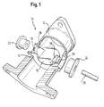
- Fig. 1 shows that in a perspective exploded view Exhaust gas recirculation valve 10 according to the invention, which in one Section 12 of an exhaust gas recirculation line is arranged, the to an intake pipe (not shown) of an engine leads.
- the valve seat 14 that defines the sealing line, formed by a paragraph.
- the valve element 16 (shown open in FIG. 1) lies in the closed state on the valve seat 14 such that the exhaust gas recirculation line is completely closed.
- the Valve element 16 comes out of the open state shown in the closed state as follows.
- Valve element extend at a point in the closed state of the valve element 16 in the shown Example is downstream (the flow of the exhaust gas can 1 from left to right done) on both sides bearing sections 18, 20 with cooperate respective bearing elements 22, 24.
- the Bearing elements 22, 24 are in suitable recesses in the Exhaust gas recirculation line used, and the bearing sections 18, 20 extend into the bearing elements 22, 24 such that the valve element 16 by a cross to the flow direction extending axis is foldable or rotatable.
- the actuation takes place in the case shown by a rotary shaft 26 which with an electrical (not shown) Actuator is connected.
- Valve element 16 which on its circumferential edge is running continuously, in the open state a little below its axis of rotation.
- This connection is at the embodiment shown by itself from that Valve element extending approaches 28 in which the Bearing sections 18, 20 are provided.
- This design essentially causes that by the inventive Exhaust gas recirculation valve the storage and the sealing effect of the Valve element 16 advantageously separated from each other can be. Because of the eccentric, so to speak Attachment of the valve element 16 with respect to its axis of rotation the valve element 16 in the example shown at Overall, closing a little against the direction of flow moves and thus comes fully to the plant Valve seat 14.
- valve element 16 is neither itself nor the valve seat 14 by the rotary bearing of the valve element 16 interrupted, leading to a high susceptibility to leakage would lead.
- the valve element alone is responsible 16 for sealing.
- the sealing line is before storage arranged so that no leakage problems at the storage may occur.
- the valve element 16, which in Fig. 1 can not be seen, with a certain thickness provided, and on its edge it (according to Fig. 1 from Viewer away) tapering, so converging beveled or designed with a spherical edge. As a result, it is reliably due to the comparatively sharp-edged valve seat 14 by an extremely simple machining can be trained.
- the storage of the Valve element 16 (seen in the closed state) not only in the direction of the flow direction of the exhaust gas eccentric, but also in a direction perpendicular to it.
- the storage is according to the illustrated embodiment (seen in the open state) with respect to the extension of the valve element 16 in Flow direction not in the middle, but in this case a little upstream, generally expressed in axial Direction of the exhaust gas recirculation line, offset.
- This is storage within the exhaust gas recirculation line offset above, so that the valve element 16 in open state in the lower area of the Exhaust gas recirculation line is located.
- the Relationships are just the other way round, and that Valve element in an upper area of the Exhaust gas recirculation line is located. This will make one possible little disturbance of the flow of the recirculated exhaust gas reached.
- FIG. 3 shows a preferred construction of the valve element 16 shown.
- This advantageously consists of one Base body 44 on which can also be seen in FIG. 1 Bearing sections 18, 20 are formed.
- On one side of the Base body 44 is used as a receptacle for the actual one Sealing ring 46, which in the closed state of the valve the valve seat 14 rests, essentially a protruding one Ring or a protruding disc 48 is provided.
- the ring or washer 48 a bit have a smaller diameter than the circular one Recess 50 in the sealing ring 46, so that the sealing ring 46 at least slightly in the lateral or radial direction is movable with respect to the base body 44.
- the sealing ring 46 as soon as it comes into contact with the Valve seat 14 comes, can align at least slightly, and possibly compensated for existing tolerances that the sealing ring 46 moves in such a way that he is at all points along its circumference reliably rests on the valve seat 14 and thus minimizes tolerance-related seat leakage.
Landscapes
- Engineering & Computer Science (AREA)
- General Engineering & Computer Science (AREA)
- Mechanical Engineering (AREA)
- Chemical & Material Sciences (AREA)
- Combustion & Propulsion (AREA)
- Exhaust-Gas Circulating Devices (AREA)
- Lift Valve (AREA)
Priority Applications (5)
| Application Number | Priority Date | Filing Date | Title |
|---|---|---|---|
| PT01107497T PT1245820E (pt) | 2001-03-29 | 2001-03-29 | Valvula de recirculacao de gases de escape |
| DE50108825T DE50108825D1 (de) | 2001-03-29 | 2001-03-29 | Abgasrückführventil |
| EP01107497A EP1245820B1 (fr) | 2001-03-29 | 2001-03-29 | Soupape de recirculation de gaz d'échappement |
| ES01107497T ES2260110T3 (es) | 2001-03-29 | 2001-03-29 | Valvula de recirculacion de gases de escape. |
| AT01107497T ATE317062T1 (de) | 2001-03-29 | 2001-03-29 | Abgasrückführventil |
Applications Claiming Priority (1)
| Application Number | Priority Date | Filing Date | Title |
|---|---|---|---|
| EP01107497A EP1245820B1 (fr) | 2001-03-29 | 2001-03-29 | Soupape de recirculation de gaz d'échappement |
Publications (2)
| Publication Number | Publication Date |
|---|---|
| EP1245820A1 true EP1245820A1 (fr) | 2002-10-02 |
| EP1245820B1 EP1245820B1 (fr) | 2006-02-01 |
Family
ID=8176939
Family Applications (1)
| Application Number | Title | Priority Date | Filing Date |
|---|---|---|---|
| EP01107497A Expired - Lifetime EP1245820B1 (fr) | 2001-03-29 | 2001-03-29 | Soupape de recirculation de gaz d'échappement |
Country Status (5)
| Country | Link |
|---|---|
| EP (1) | EP1245820B1 (fr) |
| AT (1) | ATE317062T1 (fr) |
| DE (1) | DE50108825D1 (fr) |
| ES (1) | ES2260110T3 (fr) |
| PT (1) | PT1245820E (fr) |
Cited By (9)
| Publication number | Priority date | Publication date | Assignee | Title |
|---|---|---|---|---|
| EP1544449A1 (fr) | 2003-12-19 | 2005-06-22 | Cooper-Standard Automotive (Deutschland) GmbH | Soupape de recirculation de gaz d'échappement |
| EP1657424A2 (fr) | 2004-11-10 | 2006-05-17 | Pierburg GmbH | Dispositif de recirculation de gaz d'échappement pour un moteur à combustion interne |
| DE102004040817B4 (de) * | 2004-08-24 | 2008-12-04 | Pierburg Gmbh | Abgasklappeneinrichtung |
| US7533659B2 (en) | 2006-07-06 | 2009-05-19 | Cooper-Standard Automotive (Deutchland) Gmbh | Exhaust-gas recirculation valve |
| EP2180167A1 (fr) | 2008-10-23 | 2010-04-28 | Küster Holding GmbH | Entraînement de clapet de gaz d'échappement pour véhicule automobile |
| US8353274B2 (en) | 2007-07-30 | 2013-01-15 | Cooper-Standard Automotive (Deutschland) Gmbh | Exhaust gas recirculation system |
| DE102018214069A1 (de) * | 2018-08-21 | 2020-02-27 | Continental Automotive Gmbh | Ventil zur Steuerung von Abgas oder Frischluft in einer Antriebseinheit eines Kraftfahrzeuges oder Generators |
| CN113494395A (zh) * | 2020-04-01 | 2021-10-12 | 尤姆弗泰克有限公司 | 用于有目的地进行废气再循环的控制翻盖及其制造方法 |
| DE102009016597C5 (de) | 2009-04-08 | 2023-03-23 | Küster Holding GmbH | Abgasklappenantrieb für ein Kraftfahrzeug |
Citations (9)
| Publication number | Priority date | Publication date | Assignee | Title |
|---|---|---|---|---|
| DE2241935A1 (de) | 1972-08-25 | 1974-03-07 | Bosch Gmbh Robert | Anlage zur abgasentgiftung |
| US4171689A (en) * | 1977-01-29 | 1979-10-23 | Robert Bosch Gmbh | Device for the control of gas admissions into the induction manifold of an internal combustion engine |
| US4222356A (en) | 1978-09-13 | 1980-09-16 | Toyota Jidosha Kogyo Kabushiki Kaisha | Exhaust gas recirculation for a diesel engine |
| DE2918348A1 (de) * | 1979-05-07 | 1980-11-20 | Adams Gmbh & Co Kg Armaturen & | Klappenventil mit doppelsitz |
| JPS5934471A (ja) | 1982-08-20 | 1984-02-24 | Yanmar Diesel Engine Co Ltd | 内燃機関の排気再循環装置 |
| US5148678A (en) * | 1989-12-26 | 1992-09-22 | Aisan Kogyo Kabushiki Kaisha | Exhaust gas flow control valve for internal combustion engine |
| US5531205A (en) * | 1995-03-31 | 1996-07-02 | Siemens Electric Limited | Rotary diesel electric EGR valve |
| EP0887541A2 (fr) * | 1997-06-25 | 1998-12-30 | Lucas Industries Public Limited Company | Soupape de recirculation de gaz d'échappement |
| EP1020633A1 (fr) * | 1998-07-07 | 2000-07-19 | Man Nutzfahrzeuge Ag | Vanne unidirectionnelle pour recirculation de gaz d' échappement |
-
2001
- 2001-03-29 PT PT01107497T patent/PT1245820E/pt unknown
- 2001-03-29 DE DE50108825T patent/DE50108825D1/de not_active Expired - Lifetime
- 2001-03-29 EP EP01107497A patent/EP1245820B1/fr not_active Expired - Lifetime
- 2001-03-29 ES ES01107497T patent/ES2260110T3/es not_active Expired - Lifetime
- 2001-03-29 AT AT01107497T patent/ATE317062T1/de active
Patent Citations (9)
| Publication number | Priority date | Publication date | Assignee | Title |
|---|---|---|---|---|
| DE2241935A1 (de) | 1972-08-25 | 1974-03-07 | Bosch Gmbh Robert | Anlage zur abgasentgiftung |
| US4171689A (en) * | 1977-01-29 | 1979-10-23 | Robert Bosch Gmbh | Device for the control of gas admissions into the induction manifold of an internal combustion engine |
| US4222356A (en) | 1978-09-13 | 1980-09-16 | Toyota Jidosha Kogyo Kabushiki Kaisha | Exhaust gas recirculation for a diesel engine |
| DE2918348A1 (de) * | 1979-05-07 | 1980-11-20 | Adams Gmbh & Co Kg Armaturen & | Klappenventil mit doppelsitz |
| JPS5934471A (ja) | 1982-08-20 | 1984-02-24 | Yanmar Diesel Engine Co Ltd | 内燃機関の排気再循環装置 |
| US5148678A (en) * | 1989-12-26 | 1992-09-22 | Aisan Kogyo Kabushiki Kaisha | Exhaust gas flow control valve for internal combustion engine |
| US5531205A (en) * | 1995-03-31 | 1996-07-02 | Siemens Electric Limited | Rotary diesel electric EGR valve |
| EP0887541A2 (fr) * | 1997-06-25 | 1998-12-30 | Lucas Industries Public Limited Company | Soupape de recirculation de gaz d'échappement |
| EP1020633A1 (fr) * | 1998-07-07 | 2000-07-19 | Man Nutzfahrzeuge Ag | Vanne unidirectionnelle pour recirculation de gaz d' échappement |
Cited By (13)
| Publication number | Priority date | Publication date | Assignee | Title |
|---|---|---|---|---|
| US7182315B2 (en) | 2003-12-19 | 2007-02-27 | Cooper-Standard Automotive (Deutschland) Gmbh | Exhaust-gas recirculation valve |
| CN100430593C (zh) * | 2003-12-19 | 2008-11-05 | 库帕-标准汽车(德国)有限责任公司 | 废气再循环阀 |
| EP1544449A1 (fr) | 2003-12-19 | 2005-06-22 | Cooper-Standard Automotive (Deutschland) GmbH | Soupape de recirculation de gaz d'échappement |
| DE102004040817B4 (de) * | 2004-08-24 | 2008-12-04 | Pierburg Gmbh | Abgasklappeneinrichtung |
| EP1657424A2 (fr) | 2004-11-10 | 2006-05-17 | Pierburg GmbH | Dispositif de recirculation de gaz d'échappement pour un moteur à combustion interne |
| EP1657424A3 (fr) * | 2004-11-10 | 2010-09-08 | Pierburg GmbH | Dispositif de recirculation de gaz d'échappement pour un moteur à combustion interne |
| US7533659B2 (en) | 2006-07-06 | 2009-05-19 | Cooper-Standard Automotive (Deutchland) Gmbh | Exhaust-gas recirculation valve |
| US8353274B2 (en) | 2007-07-30 | 2013-01-15 | Cooper-Standard Automotive (Deutschland) Gmbh | Exhaust gas recirculation system |
| EP2180167A1 (fr) | 2008-10-23 | 2010-04-28 | Küster Holding GmbH | Entraînement de clapet de gaz d'échappement pour véhicule automobile |
| DE102009016597C5 (de) | 2009-04-08 | 2023-03-23 | Küster Holding GmbH | Abgasklappenantrieb für ein Kraftfahrzeug |
| DE102018214069A1 (de) * | 2018-08-21 | 2020-02-27 | Continental Automotive Gmbh | Ventil zur Steuerung von Abgas oder Frischluft in einer Antriebseinheit eines Kraftfahrzeuges oder Generators |
| CN113494395A (zh) * | 2020-04-01 | 2021-10-12 | 尤姆弗泰克有限公司 | 用于有目的地进行废气再循环的控制翻盖及其制造方法 |
| CN113494395B (zh) * | 2020-04-01 | 2023-09-01 | 尤姆弗泰克有限公司 | 用于有目的地进行废气再循环的控制翻盖及其制造方法 |
Also Published As
| Publication number | Publication date |
|---|---|
| PT1245820E (pt) | 2006-06-30 |
| ATE317062T1 (de) | 2006-02-15 |
| DE50108825D1 (de) | 2006-04-13 |
| EP1245820B1 (fr) | 2006-02-01 |
| ES2260110T3 (es) | 2006-11-01 |
Similar Documents
| Publication | Publication Date | Title |
|---|---|---|
| DE60009590T2 (de) | Abgasrückführungssystem und Betätigungsvorrichtung dafür | |
| DE69810850T2 (de) | Abgasrückführungsventil | |
| EP2084439B1 (fr) | Tiroir rotatif, notamment pour un circuit de réfrigérant d'un moteur à combustion interne présentant plusieurs branches; sous-ensemble électromécanique | |
| EP0320490A2 (fr) | Obturateur | |
| DE102015200139B4 (de) | Nockenwellenverstelleranbindung an eine Doppelnockenwelle | |
| EP1347154B1 (fr) | Contrôleur de levée de soupapes d'un moteur à combustion interne | |
| WO2014033075A1 (fr) | Échangeur de chaleur des gaz d'échappement | |
| EP2089619A1 (fr) | Dispositif de régulation pour un moteur à combustion interne | |
| DE2938372A1 (de) | Brennkraftmaschine | |
| DE2924800C2 (de) | Drosselvorrichtung für eine zweiwellige Schneckenmaschine | |
| EP1245820B1 (fr) | Soupape de recirculation de gaz d'échappement | |
| EP0856657A2 (fr) | Soupape de recirculation de gaz d'échappement pour un moteur à combustion | |
| EP1332306B1 (fr) | Dispositif de reglage a rotation | |
| EP1526272B1 (fr) | Soupape de recirculation de gaz d'échappement | |
| EP3615787B1 (fr) | Vanne pour un moteur à combustion interne | |
| EP2172638B1 (fr) | Dispositif de ventilation pour la commande d'un flux de gaz d'échappement | |
| DE3842974A1 (de) | Membranvergaser mit stellungsabhaengig gekoppelter drosselklappe und chokeklappe | |
| EP2905435B1 (fr) | Moteur à combustion interne | |
| EP0348432B1 (fr) | Dispositif pour commander au moins une section d'etranglement sur au moins une ouverture de commande | |
| EP2478204B1 (fr) | Dispositif de réglage et dispositif d'accouplement | |
| DE3804333C2 (de) | Vorrichtung zur Veränderung des Steuerwinkels zwischen einem Maschinenteil und einer dieses betätigenden Antriebseinheit | |
| DE4242634A1 (en) | Combustion engine valve control mechanism - has gear and worm drive between engine crankshaft and cam shafts, gear drive having conical wheels and worm drive slidable along own axis | |
| DE69701985T2 (de) | Winkelverstellvorrichtung | |
| EP1340892A2 (fr) | Soupape pour ouverture et fermeture d'une conduite d'admission | |
| DE3504608A1 (de) | Absperrorgan fuer rohrleitungen |
Legal Events
| Date | Code | Title | Description |
|---|---|---|---|
| PUAI | Public reference made under article 153(3) epc to a published international application that has entered the european phase |
Free format text: ORIGINAL CODE: 0009012 |
|
| 17P | Request for examination filed |
Effective date: 20020215 |
|
| AK | Designated contracting states |
Kind code of ref document: A1 Designated state(s): AT BE CH CY DE DK ES FI FR GB GR IE IT LI LU MC NL PT SE TR |
|
| AX | Request for extension of the european patent |
Free format text: AL;LT;LV;MK;RO;SI |
|
| AKX | Designation fees paid |
Designated state(s): AT BE CH CY DE DK ES FI FR GB GR IE IT LI LU MC NL PT SE TR |
|
| 17Q | First examination report despatched |
Effective date: 20040811 |
|
| GRAP | Despatch of communication of intention to grant a patent |
Free format text: ORIGINAL CODE: EPIDOSNIGR1 |
|
| GRAS | Grant fee paid |
Free format text: ORIGINAL CODE: EPIDOSNIGR3 |
|
| GRAA | (expected) grant |
Free format text: ORIGINAL CODE: 0009210 |
|
| AK | Designated contracting states |
Kind code of ref document: B1 Designated state(s): AT BE CH CY DE DK ES FI FR GB GR IE IT LI LU MC NL PT SE TR |
|
| PG25 | Lapsed in a contracting state [announced via postgrant information from national office to epo] |
Ref country code: NL Free format text: LAPSE BECAUSE OF FAILURE TO SUBMIT A TRANSLATION OF THE DESCRIPTION OR TO PAY THE FEE WITHIN THE PRESCRIBED TIME-LIMIT Effective date: 20060201 Ref country code: FI Free format text: LAPSE BECAUSE OF FAILURE TO SUBMIT A TRANSLATION OF THE DESCRIPTION OR TO PAY THE FEE WITHIN THE PRESCRIBED TIME-LIMIT Effective date: 20060201 |
|
| REG | Reference to a national code |
Ref country code: GB Ref legal event code: FG4D Free format text: NOT ENGLISH |
|
| REG | Reference to a national code |
Ref country code: CH Ref legal event code: EP |
|
| REG | Reference to a national code |
Ref country code: IE Ref legal event code: FG4D Free format text: LANGUAGE OF EP DOCUMENT: GERMAN |
|
| PG25 | Lapsed in a contracting state [announced via postgrant information from national office to epo] |
Ref country code: MC Free format text: LAPSE BECAUSE OF NON-PAYMENT OF DUE FEES Effective date: 20060331 Ref country code: CH Free format text: LAPSE BECAUSE OF NON-PAYMENT OF DUE FEES Effective date: 20060331 Ref country code: LI Free format text: LAPSE BECAUSE OF NON-PAYMENT OF DUE FEES Effective date: 20060331 |
|
| REF | Corresponds to: |
Ref document number: 50108825 Country of ref document: DE Date of ref document: 20060413 Kind code of ref document: P |
|
| PG25 | Lapsed in a contracting state [announced via postgrant information from national office to epo] |
Ref country code: DK Free format text: LAPSE BECAUSE OF FAILURE TO SUBMIT A TRANSLATION OF THE DESCRIPTION OR TO PAY THE FEE WITHIN THE PRESCRIBED TIME-LIMIT Effective date: 20060501 |
|
| REG | Reference to a national code |
Ref country code: SE Ref legal event code: TRGR |
|
| GBT | Gb: translation of ep patent filed (gb section 77(6)(a)/1977) |
Effective date: 20060517 |
|
| REG | Reference to a national code |
Ref country code: PT Ref legal event code: SC4A Effective date: 20060428 |
|
| NLV1 | Nl: lapsed or annulled due to failure to fulfill the requirements of art. 29p and 29m of the patents act | ||
| ET | Fr: translation filed | ||
| REG | Reference to a national code |
Ref country code: ES Ref legal event code: FG2A Ref document number: 2260110 Country of ref document: ES Kind code of ref document: T3 |
|
| REG | Reference to a national code |
Ref country code: CH Ref legal event code: PL |
|
| PLBE | No opposition filed within time limit |
Free format text: ORIGINAL CODE: 0009261 |
|
| STAA | Information on the status of an ep patent application or granted ep patent |
Free format text: STATUS: NO OPPOSITION FILED WITHIN TIME LIMIT |
|
| 26N | No opposition filed |
Effective date: 20061103 |
|
| REG | Reference to a national code |
Ref country code: FR Ref legal event code: ST Effective date: 20070131 |
|
| REG | Reference to a national code |
Ref country code: FR Ref legal event code: RN |
|
| REG | Reference to a national code |
Ref country code: FR Ref legal event code: FC |
|
| PG25 | Lapsed in a contracting state [announced via postgrant information from national office to epo] |
Ref country code: GR Free format text: LAPSE BECAUSE OF FAILURE TO SUBMIT A TRANSLATION OF THE DESCRIPTION OR TO PAY THE FEE WITHIN THE PRESCRIBED TIME-LIMIT Effective date: 20060502 |
|
| PGRI | Patent reinstated in contracting state [announced from national office to epo] |
Ref country code: FR Effective date: 20070418 |
|
| PGRI | Patent reinstated in contracting state [announced from national office to epo] |
Ref country code: FR Effective date: 20070418 |
|
| PG25 | Lapsed in a contracting state [announced via postgrant information from national office to epo] |
Ref country code: LU Free format text: LAPSE BECAUSE OF NON-PAYMENT OF DUE FEES Effective date: 20060329 Ref country code: TR Free format text: LAPSE BECAUSE OF FAILURE TO SUBMIT A TRANSLATION OF THE DESCRIPTION OR TO PAY THE FEE WITHIN THE PRESCRIBED TIME-LIMIT Effective date: 20060201 |
|
| PG25 | Lapsed in a contracting state [announced via postgrant information from national office to epo] |
Ref country code: CY Free format text: LAPSE BECAUSE OF FAILURE TO SUBMIT A TRANSLATION OF THE DESCRIPTION OR TO PAY THE FEE WITHIN THE PRESCRIBED TIME-LIMIT Effective date: 20060201 |
|
| PG25 | Lapsed in a contracting state [announced via postgrant information from national office to epo] |
Ref country code: IT Free format text: LAPSE BECAUSE OF NON-PAYMENT OF DUE FEES Effective date: 20110329 |
|
| PGFP | Annual fee paid to national office [announced via postgrant information from national office to epo] |
Ref country code: IT Payment date: 20120320 Year of fee payment: 11 |
|
| PG25 | Lapsed in a contracting state [announced via postgrant information from national office to epo] |
Ref country code: IT Free format text: LAPSE BECAUSE OF NON-PAYMENT OF DUE FEES Effective date: 20120329 |
|
| REG | Reference to a national code |
Ref country code: FR Ref legal event code: PLFP Year of fee payment: 16 |
|
| REG | Reference to a national code |
Ref country code: PT Ref legal event code: PC4A Owner name: , KR Effective date: 20160603 |
|
| REG | Reference to a national code |
Ref country code: FR Ref legal event code: PLFP Year of fee payment: 17 |
|
| REG | Reference to a national code |
Ref country code: ES Ref legal event code: PC2A Owner name: HANON SYSTEMS Effective date: 20170310 |
|
| REG | Reference to a national code |
Ref country code: FR Ref legal event code: CA Effective date: 20170828 Ref country code: FR Ref legal event code: CD Owner name: HANON SYSTEMS, KR Effective date: 20170830 Ref country code: FR Ref legal event code: TP Owner name: HANON SYSTEMS, KR Effective date: 20170830 |
|
| REG | Reference to a national code |
Ref country code: FR Ref legal event code: PLFP Year of fee payment: 18 |
|
| PGFP | Annual fee paid to national office [announced via postgrant information from national office to epo] |
Ref country code: SE Payment date: 20200310 Year of fee payment: 20 Ref country code: DE Payment date: 20200317 Year of fee payment: 20 Ref country code: PT Payment date: 20200324 Year of fee payment: 20 Ref country code: IE Payment date: 20200309 Year of fee payment: 20 Ref country code: GB Payment date: 20200318 Year of fee payment: 20 Ref country code: AT Payment date: 20200225 Year of fee payment: 20 |
|
| PGFP | Annual fee paid to national office [announced via postgrant information from national office to epo] |
Ref country code: BE Payment date: 20200217 Year of fee payment: 20 |
|
| PGFP | Annual fee paid to national office [announced via postgrant information from national office to epo] |
Ref country code: FR Payment date: 20200227 Year of fee payment: 20 |
|
| PGFP | Annual fee paid to national office [announced via postgrant information from national office to epo] |
Ref country code: ES Payment date: 20200401 Year of fee payment: 20 |
|
| REG | Reference to a national code |
Ref country code: AT Ref legal event code: PC Ref document number: 317062 Country of ref document: AT Kind code of ref document: T Owner name: HANON SYSTEMS, KR Effective date: 20200629 |
|
| REG | Reference to a national code |
Ref country code: DE Ref legal event code: R071 Ref document number: 50108825 Country of ref document: DE |
|
| REG | Reference to a national code |
Ref country code: GB Ref legal event code: PE20 Expiry date: 20210328 |
|
| REG | Reference to a national code |
Ref country code: IE Ref legal event code: MK9A |
|
| PG25 | Lapsed in a contracting state [announced via postgrant information from national office to epo] |
Ref country code: GB Free format text: LAPSE BECAUSE OF EXPIRATION OF PROTECTION Effective date: 20210328 |
|
| REG | Reference to a national code |
Ref country code: BE Ref legal event code: MK Effective date: 20210329 |
|
| REG | Reference to a national code |
Ref country code: AT Ref legal event code: MK07 Ref document number: 317062 Country of ref document: AT Kind code of ref document: T Effective date: 20210329 |
|
| PG25 | Lapsed in a contracting state [announced via postgrant information from national office to epo] |
Ref country code: PT Free format text: LAPSE BECAUSE OF EXPIRATION OF PROTECTION Effective date: 20210408 |
|
| REG | Reference to a national code |
Ref country code: ES Ref legal event code: FD2A Effective date: 20210730 |
|
| PG25 | Lapsed in a contracting state [announced via postgrant information from national office to epo] |
Ref country code: IE Free format text: LAPSE BECAUSE OF EXPIRATION OF PROTECTION Effective date: 20210329 |
|
| REG | Reference to a national code |
Ref country code: SE Ref legal event code: EUG |
|
| PG25 | Lapsed in a contracting state [announced via postgrant information from national office to epo] |
Ref country code: ES Free format text: LAPSE BECAUSE OF EXPIRATION OF PROTECTION Effective date: 20210330 |