EP1245854A2 - Amortisseur bi-mode, controlé par un élément magnétostrictif, pour une suspension - Google Patents
Amortisseur bi-mode, controlé par un élément magnétostrictif, pour une suspension Download PDFInfo
- Publication number
- EP1245854A2 EP1245854A2 EP02075953A EP02075953A EP1245854A2 EP 1245854 A2 EP1245854 A2 EP 1245854A2 EP 02075953 A EP02075953 A EP 02075953A EP 02075953 A EP02075953 A EP 02075953A EP 1245854 A2 EP1245854 A2 EP 1245854A2
- Authority
- EP
- European Patent Office
- Prior art keywords
- suspension damper
- piston
- movable member
- magnetic field
- cavity
- Prior art date
- Legal status (The legal status is an assumption and is not a legal conclusion. Google has not performed a legal analysis and makes no representation as to the accuracy of the status listed.)
- Granted
Links
- 239000000725 suspension Substances 0.000 title claims abstract description 38
- 230000009977 dual effect Effects 0.000 title description 2
- 238000013016 damping Methods 0.000 claims abstract description 34
- 238000004891 communication Methods 0.000 claims abstract description 21
- 239000012530 fluid Substances 0.000 claims abstract description 20
- 239000000463 material Substances 0.000 claims description 22
- 239000008188 pellet Substances 0.000 claims description 22
- 230000006835 compression Effects 0.000 claims description 4
- 238000007906 compression Methods 0.000 claims description 4
- 238000004804 winding Methods 0.000 description 13
- 125000006850 spacer group Chemical group 0.000 description 4
- PXHVJJICTQNCMI-UHFFFAOYSA-N Nickel Chemical compound [Ni] PXHVJJICTQNCMI-UHFFFAOYSA-N 0.000 description 2
- 239000006096 absorbing agent Substances 0.000 description 2
- 230000004323 axial length Effects 0.000 description 2
- 230000000903 blocking effect Effects 0.000 description 2
- 230000000694 effects Effects 0.000 description 2
- 230000010355 oscillation Effects 0.000 description 2
- 230000035939 shock Effects 0.000 description 2
- 150000001875 compounds Chemical class 0.000 description 1
- 238000006073 displacement reaction Methods 0.000 description 1
- 229920001971 elastomer Polymers 0.000 description 1
- 239000000806 elastomer Substances 0.000 description 1
- 229910052759 nickel Inorganic materials 0.000 description 1
- 230000000717 retained effect Effects 0.000 description 1
- 238000007789 sealing Methods 0.000 description 1
- 229920002379 silicone rubber Polymers 0.000 description 1
- 239000004945 silicone rubber Substances 0.000 description 1
- 239000007779 soft material Substances 0.000 description 1
Images




Classifications
-
- F—MECHANICAL ENGINEERING; LIGHTING; HEATING; WEAPONS; BLASTING
- F16—ENGINEERING ELEMENTS AND UNITS; GENERAL MEASURES FOR PRODUCING AND MAINTAINING EFFECTIVE FUNCTIONING OF MACHINES OR INSTALLATIONS; THERMAL INSULATION IN GENERAL
- F16F—SPRINGS; SHOCK-ABSORBERS; MEANS FOR DAMPING VIBRATION
- F16F9/00—Springs, vibration-dampers, shock-absorbers, or similarly-constructed movement-dampers using a fluid or the equivalent as damping medium
- F16F9/32—Details
- F16F9/34—Special valve constructions; Shape or construction of throttling passages
- F16F9/348—Throttling passages in the form of annular discs or other plate-like elements which may or may not have a spring action, operating in opposite directions or singly, e.g. annular discs positioned on top of the valve or piston body
- F16F9/3482—Throttling passages in the form of annular discs or other plate-like elements which may or may not have a spring action, operating in opposite directions or singly, e.g. annular discs positioned on top of the valve or piston body the annular discs being incorporated within the valve or piston body
-
- F—MECHANICAL ENGINEERING; LIGHTING; HEATING; WEAPONS; BLASTING
- F16—ENGINEERING ELEMENTS AND UNITS; GENERAL MEASURES FOR PRODUCING AND MAINTAINING EFFECTIVE FUNCTIONING OF MACHINES OR INSTALLATIONS; THERMAL INSULATION IN GENERAL
- F16F—SPRINGS; SHOCK-ABSORBERS; MEANS FOR DAMPING VIBRATION
- F16F9/00—Springs, vibration-dampers, shock-absorbers, or similarly-constructed movement-dampers using a fluid or the equivalent as damping medium
- F16F9/32—Details
- F16F9/44—Means on or in the damper for manual or non-automatic adjustment; such means combined with temperature correction
- F16F9/46—Means on or in the damper for manual or non-automatic adjustment; such means combined with temperature correction allowing control from a distance, i.e. location of means for control input being remote from site of valves, e.g. on damper external wall
- F16F9/461—Means on or in the damper for manual or non-automatic adjustment; such means combined with temperature correction allowing control from a distance, i.e. location of means for control input being remote from site of valves, e.g. on damper external wall characterised by actuation means
-
- F—MECHANICAL ENGINEERING; LIGHTING; HEATING; WEAPONS; BLASTING
- F16—ENGINEERING ELEMENTS AND UNITS; GENERAL MEASURES FOR PRODUCING AND MAINTAINING EFFECTIVE FUNCTIONING OF MACHINES OR INSTALLATIONS; THERMAL INSULATION IN GENERAL
- F16F—SPRINGS; SHOCK-ABSORBERS; MEANS FOR DAMPING VIBRATION
- F16F9/00—Springs, vibration-dampers, shock-absorbers, or similarly-constructed movement-dampers using a fluid or the equivalent as damping medium
- F16F9/32—Details
- F16F9/44—Means on or in the damper for manual or non-automatic adjustment; such means combined with temperature correction
- F16F9/46—Means on or in the damper for manual or non-automatic adjustment; such means combined with temperature correction allowing control from a distance, i.e. location of means for control input being remote from site of valves, e.g. on damper external wall
- F16F9/466—Throttling control, i.e. regulation of flow passage geometry
-
- F—MECHANICAL ENGINEERING; LIGHTING; HEATING; WEAPONS; BLASTING
- F16—ENGINEERING ELEMENTS AND UNITS; GENERAL MEASURES FOR PRODUCING AND MAINTAINING EFFECTIVE FUNCTIONING OF MACHINES OR INSTALLATIONS; THERMAL INSULATION IN GENERAL
- F16F—SPRINGS; SHOCK-ABSORBERS; MEANS FOR DAMPING VIBRATION
- F16F2224/00—Materials; Material properties
- F16F2224/02—Materials; Material properties solids
- F16F2224/0283—Materials; Material properties solids piezoelectric; electro- or magnetostrictive
Definitions
- This invention relates to a dual mode suspension damper which is switched between different levels of damping by a magnetostrictive element controlled by a magnetic field.
- Vehicle suspension systems require suspension dampers (such as shock absorbers or struts) to control oscillations in the vehicle suspension system.
- Conventional dampers include a housing filled with damping fluid and a piston slidable in the housing.
- a piston rod extends from the housing and connects the piston to the sprung mass (body) of the vehicle, while the housing is attached to an unsprung mass of the vehicle.
- Appropriate valving within the piston controls communication of damping fluid across the piston, to thereby dampen the suspension oscillations. Since conventional dampers have only a single valve in the piston and therefore are able to damp only at a set damping force, such dampers involve compromises in vehicle suspension performance.
- variable suspension dampers in which the damping level can be varied between two separate levels in response to varying vehicle operating conditions as sensed by sensors on the vehicle.
- a damper is disclosed in U.S. Patent 5,690,195.
- two separate flow paths with separate valving are provided through the piston.
- a solenoid valve controls communication through one of the flow paths. Accordingly, damping can be adjusted or varied between two different levels, depending upon vehicle operating conditions.
- parallel paths are provided through the piston of a suspension damper, each of which are provided with separate damping valving. Communication through one of the paths is controlled by a movable valve element, which is controlled by a magnetostrictive element which deforms in response to application of a magnetic field.
- the movable valve element responds to changes in the magnetostrictive element as a result of application of a magnetic field to open or close the corresponding path.
- Magnetostrictive materials used to fabricate the magnetostrictive elements used in this invention include nickel and various other compounds available commercially.
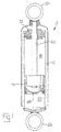
- a suspension damper such as a shock absorber, is generally indicated by the numeral 10 and includes a cylindrical housing 12 filled with damping fluid.
- a piston 14 is slidable within the housing 12 and divides the latter into a compression chamber 16 and a rebound chamber 18.
- a piston rod 20 extends from the piston 14 through the rebound chamber 18 and closure member 22.
- An attachment fitting 24 on piston rod 20 permits the piston rod 20 to be secured to the sprung mass of the vehicle (the vehicle body) and an attachment fitting 26 on housing 12 permits the housing 12 to be secured to an unsprung mass of the vehicle.
- a conventional gas cap 28 slides in the compression chamber 16 and separates the latter from gas chamber 30, which is charged with compressed gas in a conventional manner to permit the damper 10 to accommodate changes in volume of the rebound chamber 18 in response to changes in volume of the piston rod within rebound chamber 18 in response to movement of the piston 14. Gas cap 28 also reduces cavitation of the damping fluid, all in a manner well known to those skilled in the art.
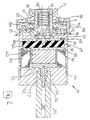
- the piston 14 includes an outer case 32 which defines a cavity therewithin.
- the outer case is stepped to define a larger diameter portion 34 and a smaller diameter portion 36 so that the cavity includes larger and smaller diameter portions 38,40 respectively.
- the larger portion 34 is closed by a cover 42 through a threaded connection generally indicated by the numeral 44.
- the portion of the outer case 32 engaged by the cover 42 terminates in multiple circumferentially spaced tabs 46, and the corresponding portion of the cover 42 is provided with circumferentially spaced recesses 48. Accordingly, the cover can be locked in place relative to the outer case 32 by deflecting one or move of the tabs 46 with a corresponding recess 48, as will hereinafter be explained.
- the piston rod 20 is secured to the cover 42 through a threaded connection 50.
- a bobbin 52 which carries coil windings 54.
- An electrical connector 56 extends from the bobbin 52 and into a bore 58 that extends through the piston rod 20. Electrical connector 56 is sealed to piston rod 20 by circumferentially extending seal 57.
- An electrical cable (not shown) extends through bore 58 to carry electrical power to the windings 54 through the electrical connector 56.
- the piston rod 20 provides an electrical ground to complete the power circuit to the windings 54 in a manner well known to those skilled in the art.
- the side of the bobbin 52 facing away from the cover is provided with a recess that extends into the portion of the bobbin 52 circumscribed by the windings 54.
- pellet 60 which receives a pellet 60 of magnetostrictive material. Accordingly, pellet 60 will be within the magnetic field generated by electrical power transmitted to the windings 54.
- the magetostrictive material has been described in more detail above, and has the property of constricting (shrinking) in the axial direction (that is, the direction extending along the axis of the coil) in response to an applied magnetic field.
- a disc-shaped transfer plate 62 extends across larger cavity portion 38 and is engaged by the pellet 60 and transfers the deformation of the pellet 60 as a result of the magnetic field applied thereto to a transfer medium 64.
- the transfer plate 62, outer case 32 and cover 42 define a magnetic circuit and are made of magnetically soft material.
- the transfer medium 64 is a disc of a shape compliant elastomer, such as silicone rubber that is contained between the transfer plate 62 and a pin guide 66.
- Pin guide 66 rests on shoulder 68 defined between larger and smaller portions of the outer case 32, and includes an aperture 68 along the axis thereof that slidably receives a pin 70 that projects from a movable valve spool member 72 that is slidable within smaller diameter cavity portion 40.
- the spool valve member 72 is urged toward the pin guide 66 by a spring 74, which is mounted in the cavity portion 40 and is held in place by a clip 76.
- the spring 74 bears against the end 78 of the spool valve member 72 opposite the end 80 from which the pin 70 extends.
- the end 80 includes slot 81 through which damping fluid communicates through the spool valve member 72.
- a first set of circumerentially extending valve elements 82 and a second set of circumerentially extending valve elements 84 are each supported on the outer circumferential surface of smaller portion 36 of case 32 and are separated by a circumferentially extending spacer 86.
- the valve sets 82 and 84 are described in detail in the above-mentioned U.S. Patent 5,690,195, and, since they form no part of the present invention, will not be described in detail herein.
- valve sets 82 and 84 regulate flow of damping fluid across the piston 14 and thus provide damping.
- the valve sets 82, 84 and spacer 86 are not shown in FIGURE 3.
- a piston cap 88 is mounted on smaller portion 36 and holds the valve sets 82, 84 and spacer 86 in position.
- the outer circumferential surface of piston cap 88 is provided with seals and sealing grooves 90, which sealingly engage the inner wall of housing 12.
- Circumferentially spaced apertures 92 are provided in the piston cap 88, and define a portion of a first fluid path indicated by the arrow A that is controlled by valve set 82.
- Circumferentially spaced apertures 94 are provided through the smaller portion 36 near the end thereof through which the pin 70 extends. The apertures 94 define a portion of a second fluid path indicated by arrow B, that is controlled by the valve set 84.
- Communication through the second fluid path is controlled by the movable spool valve 72, which in one position closes communication through the aoertyres 94 but is movable to a position which opens communication through the apertures 94.
- the movable spool valve 72 is calibrated when the piston 14 is assembled, by advancing the cover 42 on the case 32 until the valve spool 72 attains a predetermined position, at which one or move of the tabs 46 are deflected into a corresponding registering recess 48, to thereby lock the cover in position.
- the magnetostrictive pellet 60 shrinks or constricts. Accordingly the transfer plate 62 is permitted to move toward the cover 42, which in turn allows the spring 74 acting through valve spool member 72 to push the pin 70 into transfer medium 64, thereby moving the valve spool member into a position closing the apertures 94, thereby preventing communication of damping fluid through apertures 94. Accordingly, communication of damping fluid through flow path B is prevented, so all damping is provided through flow path A and the first set of valve elements 82.
- valve spool member 72 When the windings 54 are deactivated, the valve spool member 72 is pushed away from vavle guide 66, so that damping is provided through both fluid flow paths A and B and both sets of valve members 82 and 84.
- the spool valve element may be designed so that the normal position either blocks or opens the apertures 94, so that energization of the windings 54 either adds or removes the damping provided by the flow path B through second valve elements 84.
- the effect of the magnetostrictive pellet is enhanced by using a telescoping structure in which another magnetostrictive pellet 96 is nested within a cavity 98 formed in magnetostrictive pellet 100 and held in place by a support member 102, which is made of a non-magnetostrictive material.
- the displacement generated by the combined pellets 96 and 100 is the same as that of a single element with an axial length equal to the sum of the axial lengths of the two nested pellets, but the package size is smaller.
- FIGURES 2, 3, and 4 may also be used with a magnetosrrictive pellet that expands upon application of a magnetic field, in which case the effect of the magnetic field on the postion of the valving would be reversed; in other words,the position of the valve 72 attained with a strong magnetic field with a constricting pellet 72 will require a weak magnetic field with an expanding pellet.
- the valve 72 may be provided with slots on the circumferentially extending surface thereof instead of the slot on end 81 may be used so that the valve 72 will be moved into the position allowing communication through flow path B by applying a magnetic field thereto.
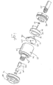
- the spool vlave member 72 is replaced by a rotary valve member 104, which is rotatable within the cavity smaller portion 40 and supported by a spacer/thrust bearing 105, which is retained by clip 106.
- the rotary valve member 104 is provided with multiple, circumferentially spaced, axially extending slots 108.
- the slots 108 are designed so that in a predetermined angular orientation of the rotary valve member 104 the slots 108 are aligned with the apertures 94, to thus permit communication of damping fluid through the second set of valve members 84 and flow bath B. However, upon rotation of the rotary valve member 104, communication through the apertures 94 and the valve set 84 is blocked, to thereby remove the damping provided by the valve set 84.
- the rotary valve member 104 is operated by a spiral wound bimetalic element generally indicated by the numeral 110.
- Spiral bimetallic element 110 is made by bonding a sheet of magnetostrictive material to a sheet of non-magnetostrictive material of similar thickness, cutting the material into strips of an appropriate length, and then winding the strips into the spiral 110.
- the outer end 112 is secured to a pin 114, which is rigidly secured to a support plate 116, which is held against rotation relative to case 32 by projection 118.
- Support plate 116 supports the spiral element 110 nested within coil windings 54.
- the inner end 120 of spiral bimetallic element 110 is rigidly secured to a drive pin 122 which extends through a central aperture in support plate 116 and is rotatable relative thereto.
- Flats 124 are provided on the end of drive pin 122 engage corresponding flats 125 on the rotary valve member 104, to permit spiral 110 to drive the rotary valve member 104.
- the spiral bimetallic element 110 reacts to a magnetic field generated by coil windings 54 to rotate the rotary valve member 104 between positions permitting and blocking communication through the second set of valve elements 82 in flow path B, thereby changing the damper 10 between the mode in which all damping is provided by valve set 82 and the mode in which damping is provided by both the valve set 82 and the valve set 84.
- a movable spool valve member 126 is provided with slot 128 that, depending upon the axial position of the spool valve member 126 within smaller cavity portion 40, either blocks communication through apertures 94 or permits communication through apertures 94.
- Spring 74 urges spool valve member 126 into enggagement with a bimetallic coil spring 128, so that the spool valve member 126 remains engaged with coil spring 128 as spring 128 expands and contracts.
- Spring 128 is within the magnetic field of coil windings 54 and is made of a magnetostrictive material 130 bonded to a non-magnetostrictive material 132.
- Spring 128 is made of two elongate strips, one of the strips being a magnetostrictive material and the other strip being a non-magnetostrictive material. The two strips are then bonded together to form a bimetallic wire having a circular cross-section. This wire is then twisted about its axis, to form a straight wire with the two materials spiraling about the wire. The wire is then coiled to form coil spring 128.
- the spring 128 expands and contracts in response to the magnetic field applied by coil windings 54, to thereby move the spool valve member 128 between the positions blocking or enabling communication through apertures 94.
- one end of spring 128 may be fixted to the piston and the other end secured to the spool valve member 128, thereby eliminating the spring 76.
Landscapes
- Engineering & Computer Science (AREA)
- General Engineering & Computer Science (AREA)
- Mechanical Engineering (AREA)
- Fluid-Damping Devices (AREA)
- Vehicle Body Suspensions (AREA)
Priority Applications (1)
| Application Number | Priority Date | Filing Date | Title |
|---|---|---|---|
| EP06001189A EP1647735B1 (fr) | 2001-03-28 | 2002-03-12 | Amortisseur bi-mode, contrôlé par un élément magnétostrictif pour une suspension |
Applications Claiming Priority (2)
| Application Number | Priority Date | Filing Date | Title |
|---|---|---|---|
| US820190 | 2001-03-28 | ||
| US09/820,190 US6422360B1 (en) | 2001-03-28 | 2001-03-28 | Dual mode suspension damper controlled by magnetostrictive element |
Related Child Applications (1)
| Application Number | Title | Priority Date | Filing Date |
|---|---|---|---|
| EP06001189A Division EP1647735B1 (fr) | 2001-03-28 | 2002-03-12 | Amortisseur bi-mode, contrôlé par un élément magnétostrictif pour une suspension |
Publications (3)
| Publication Number | Publication Date |
|---|---|
| EP1245854A2 true EP1245854A2 (fr) | 2002-10-02 |
| EP1245854A3 EP1245854A3 (fr) | 2004-01-02 |
| EP1245854B1 EP1245854B1 (fr) | 2006-06-28 |
Family
ID=25230129
Family Applications (2)
| Application Number | Title | Priority Date | Filing Date |
|---|---|---|---|
| EP06001189A Expired - Lifetime EP1647735B1 (fr) | 2001-03-28 | 2002-03-12 | Amortisseur bi-mode, contrôlé par un élément magnétostrictif pour une suspension |
| EP02075953A Expired - Lifetime EP1245854B1 (fr) | 2001-03-28 | 2002-03-12 | Amortisseur bi-mode, controlé par un élément magnétostrictif, pour une suspension |
Family Applications Before (1)
| Application Number | Title | Priority Date | Filing Date |
|---|---|---|---|
| EP06001189A Expired - Lifetime EP1647735B1 (fr) | 2001-03-28 | 2002-03-12 | Amortisseur bi-mode, contrôlé par un élément magnétostrictif pour une suspension |
Country Status (3)
| Country | Link |
|---|---|
| US (1) | US6422360B1 (fr) |
| EP (2) | EP1647735B1 (fr) |
| DE (2) | DE60229311D1 (fr) |
Cited By (16)
| Publication number | Priority date | Publication date | Assignee | Title |
|---|---|---|---|---|
| US6871553B2 (en) | 2003-03-28 | 2005-03-29 | Delphi Technologies, Inc. | Integrating fluxgate for magnetostrictive torque sensors |
| US6872427B2 (en) | 2003-02-07 | 2005-03-29 | Delphi Technologies, Inc. | Method for producing electrical contacts using selective melting and a low pressure kinetic spray process |
| US6896933B2 (en) | 2002-04-05 | 2005-05-24 | Delphi Technologies, Inc. | Method of maintaining a non-obstructed interior opening in kinetic spray nozzles |
| US6924249B2 (en) | 2002-10-02 | 2005-08-02 | Delphi Technologies, Inc. | Direct application of catalysts to substrates via a thermal spray process for treatment of the atmosphere |
| US6949300B2 (en) | 2001-08-15 | 2005-09-27 | Delphi Technologies, Inc. | Product and method of brazing using kinetic sprayed coatings |
| US7001671B2 (en) | 2001-10-09 | 2006-02-21 | Delphi Technologies, Inc. | Kinetic sprayed electrical contacts on conductive substrates |
| US7024946B2 (en) | 2004-01-23 | 2006-04-11 | Delphi Technologies, Inc. | Assembly for measuring movement of and a torque applied to a shaft |
| US7108893B2 (en) | 2002-09-23 | 2006-09-19 | Delphi Technologies, Inc. | Spray system with combined kinetic spray and thermal spray ability |
| US7335341B2 (en) | 2003-10-30 | 2008-02-26 | Delphi Technologies, Inc. | Method for securing ceramic structures and forming electrical connections on the same |
| US7351450B2 (en) | 2003-10-02 | 2008-04-01 | Delphi Technologies, Inc. | Correcting defective kinetically sprayed surfaces |
| US7476422B2 (en) | 2002-05-23 | 2009-01-13 | Delphi Technologies, Inc. | Copper circuit formed by kinetic spray |
| US7475831B2 (en) | 2004-01-23 | 2009-01-13 | Delphi Technologies, Inc. | Modified high efficiency kinetic spray nozzle |
| US7674076B2 (en) | 2006-07-14 | 2010-03-09 | F. W. Gartner Thermal Spraying, Ltd. | Feeder apparatus for controlled supply of feedstock |
| DE102010000547A1 (de) | 2010-02-25 | 2011-08-25 | hofer driveline GmbH, 65439 | Entkopplungselement und Schaltgetriebebetätigungseinrichtung mit einem solchen Entkopplungselement |
| US20140138197A1 (en) * | 2011-07-17 | 2014-05-22 | Honda Motor Co., Ltd. | Damper with variable damping force |
| KR20160080721A (ko) | 2014-12-30 | 2016-07-08 | 주식회사 만도 | 솔레노이드 밸브 어셈블리가 구비된 전자 제어 댐퍼의 횡압 저감 장치 |
Families Citing this family (22)
| Publication number | Priority date | Publication date | Assignee | Title |
|---|---|---|---|---|
| US6668986B2 (en) * | 2002-01-08 | 2003-12-30 | Delphi Technologies, Inc. | Active hydraulic fluid vehicular suspension damper |
| US20040101620A1 (en) * | 2002-11-22 | 2004-05-27 | Elmoursi Alaa A. | Method for aluminum metalization of ceramics for power electronics applications |
| US20040142198A1 (en) * | 2003-01-21 | 2004-07-22 | Thomas Hubert Van Steenkiste | Magnetostrictive/magnetic material for use in torque sensors |
| US6880483B2 (en) * | 2003-02-07 | 2005-04-19 | Delphi Technologies, Inc. | Active seat suspension for watercraft |
| US6883649B2 (en) | 2003-03-21 | 2005-04-26 | Delphi Technologies, Inc. | Closing system for a magneto-rheological damper |
| US7125586B2 (en) * | 2003-04-11 | 2006-10-24 | Delphi Technologies, Inc. | Kinetic spray application of coatings onto covered materials |
| US6941824B2 (en) * | 2003-04-25 | 2005-09-13 | Delphi Technologies, Inc. | Magnetic force sensor and control circuit for same |
| US6899313B2 (en) * | 2003-06-25 | 2005-05-31 | Delphi Technologies, Inc. | Magnetic actuator and method |
| US6877526B2 (en) * | 2003-07-02 | 2005-04-12 | Delphi Technologies, Inc. | Magnetic actuator and method |
| US20050040260A1 (en) * | 2003-08-21 | 2005-02-24 | Zhibo Zhao | Coaxial low pressure injection method and a gas collimator for a kinetic spray nozzle |
| US20050214474A1 (en) * | 2004-03-24 | 2005-09-29 | Taeyoung Han | Kinetic spray nozzle system design |
| US20060038044A1 (en) * | 2004-08-23 | 2006-02-23 | Van Steenkiste Thomas H | Replaceable throat insert for a kinetic spray nozzle |
| US20060040048A1 (en) * | 2004-08-23 | 2006-02-23 | Taeyoung Han | Continuous in-line manufacturing process for high speed coating deposition via a kinetic spray process |
| US20070074656A1 (en) * | 2005-10-04 | 2007-04-05 | Zhibo Zhao | Non-clogging powder injector for a kinetic spray nozzle system |
| US20090071776A1 (en) * | 2007-09-13 | 2009-03-19 | Stephen Carey Hagwood | Bi-state solenoid with integral rebound cut-off |
| US8678478B2 (en) * | 2008-12-15 | 2014-03-25 | Caterpillar Inc. | Machine configurations employing passive and controllable cab mounts |
| US20120211318A1 (en) * | 2011-02-17 | 2012-08-23 | GM Global Technology Operations LLC | Real-Time Variable Damping Module Using Magnetic Shape Memory Material |
| DE102015107248B4 (de) * | 2015-05-08 | 2018-10-18 | Thyssenkrupp Ag | Regelbarer Schwingungsdämpfer |
| CN108706049B (zh) * | 2018-05-25 | 2023-06-06 | 西南交通大学 | 一种动态特性可调的汽车副车架与车身连接装置 |
| US11211896B1 (en) | 2021-01-14 | 2021-12-28 | FTC Solar, Inc. | Systems for damping a solar photovoltaic array tracker |
| DE102021201889B3 (de) | 2021-03-01 | 2022-07-14 | Zf Friedrichshafen Ag | Spulenanordnung für ein verstellbares Dämpfventil |
| US11695370B2 (en) | 2021-07-27 | 2023-07-04 | FTC Solar, Inc. | Locking assembly for a solar photovoltaic array tracker |
Citations (1)
| Publication number | Priority date | Publication date | Assignee | Title |
|---|---|---|---|---|
| US5690195A (en) | 1996-07-29 | 1997-11-25 | General Motors Corporation | Alternating state pressure regulation valved damper |
Family Cites Families (7)
| Publication number | Priority date | Publication date | Assignee | Title |
|---|---|---|---|---|
| DE2931874C2 (de) * | 1979-08-06 | 1983-08-04 | Audi Nsu Auto Union Ag, 7107 Neckarsulm | Elektrisch betätigbares Ventil |
| US5454452A (en) * | 1988-02-22 | 1995-10-03 | Ohlins Racing Ab | Absorber arrangement |
| JPH03107634A (ja) * | 1989-09-20 | 1991-05-08 | Mazda Motor Corp | サスペンションダンパー装置 |
| GB2239506B (en) * | 1989-12-08 | 1993-08-25 | Toyota Motor Co Ltd | Suspension control system |
| JPH04102738A (ja) * | 1990-08-14 | 1992-04-03 | Kayaba Ind Co Ltd | 減衰力調整装置 |
| JPH04175533A (ja) * | 1990-11-05 | 1992-06-23 | Nissan Motor Co Ltd | 圧電アクチュエータの変位拡大機構 |
| US5163659A (en) * | 1990-12-11 | 1992-11-17 | Monroe Auto Equipment Company | Hydraulic actuator for leveling system |
-
2001
- 2001-03-28 US US09/820,190 patent/US6422360B1/en not_active Expired - Fee Related
-
2002
- 2002-03-12 EP EP06001189A patent/EP1647735B1/fr not_active Expired - Lifetime
- 2002-03-12 DE DE60229311T patent/DE60229311D1/de not_active Expired - Lifetime
- 2002-03-12 DE DE60212750T patent/DE60212750T2/de not_active Expired - Fee Related
- 2002-03-12 EP EP02075953A patent/EP1245854B1/fr not_active Expired - Lifetime
Patent Citations (1)
| Publication number | Priority date | Publication date | Assignee | Title |
|---|---|---|---|---|
| US5690195A (en) | 1996-07-29 | 1997-11-25 | General Motors Corporation | Alternating state pressure regulation valved damper |
Cited By (17)
| Publication number | Priority date | Publication date | Assignee | Title |
|---|---|---|---|---|
| US6949300B2 (en) | 2001-08-15 | 2005-09-27 | Delphi Technologies, Inc. | Product and method of brazing using kinetic sprayed coatings |
| US7001671B2 (en) | 2001-10-09 | 2006-02-21 | Delphi Technologies, Inc. | Kinetic sprayed electrical contacts on conductive substrates |
| US6896933B2 (en) | 2002-04-05 | 2005-05-24 | Delphi Technologies, Inc. | Method of maintaining a non-obstructed interior opening in kinetic spray nozzles |
| US7476422B2 (en) | 2002-05-23 | 2009-01-13 | Delphi Technologies, Inc. | Copper circuit formed by kinetic spray |
| US7108893B2 (en) | 2002-09-23 | 2006-09-19 | Delphi Technologies, Inc. | Spray system with combined kinetic spray and thermal spray ability |
| US6924249B2 (en) | 2002-10-02 | 2005-08-02 | Delphi Technologies, Inc. | Direct application of catalysts to substrates via a thermal spray process for treatment of the atmosphere |
| US6872427B2 (en) | 2003-02-07 | 2005-03-29 | Delphi Technologies, Inc. | Method for producing electrical contacts using selective melting and a low pressure kinetic spray process |
| US6871553B2 (en) | 2003-03-28 | 2005-03-29 | Delphi Technologies, Inc. | Integrating fluxgate for magnetostrictive torque sensors |
| US7351450B2 (en) | 2003-10-02 | 2008-04-01 | Delphi Technologies, Inc. | Correcting defective kinetically sprayed surfaces |
| US7335341B2 (en) | 2003-10-30 | 2008-02-26 | Delphi Technologies, Inc. | Method for securing ceramic structures and forming electrical connections on the same |
| US7024946B2 (en) | 2004-01-23 | 2006-04-11 | Delphi Technologies, Inc. | Assembly for measuring movement of and a torque applied to a shaft |
| US7475831B2 (en) | 2004-01-23 | 2009-01-13 | Delphi Technologies, Inc. | Modified high efficiency kinetic spray nozzle |
| US7674076B2 (en) | 2006-07-14 | 2010-03-09 | F. W. Gartner Thermal Spraying, Ltd. | Feeder apparatus for controlled supply of feedstock |
| DE102010000547A1 (de) | 2010-02-25 | 2011-08-25 | hofer driveline GmbH, 65439 | Entkopplungselement und Schaltgetriebebetätigungseinrichtung mit einem solchen Entkopplungselement |
| US20140138197A1 (en) * | 2011-07-17 | 2014-05-22 | Honda Motor Co., Ltd. | Damper with variable damping force |
| US9126467B2 (en) * | 2011-07-17 | 2015-09-08 | Honda Motor Co., Ltd. | Damper with variable damping force |
| KR20160080721A (ko) | 2014-12-30 | 2016-07-08 | 주식회사 만도 | 솔레노이드 밸브 어셈블리가 구비된 전자 제어 댐퍼의 횡압 저감 장치 |
Also Published As
| Publication number | Publication date |
|---|---|
| US6422360B1 (en) | 2002-07-23 |
| EP1245854B1 (fr) | 2006-06-28 |
| EP1647735A1 (fr) | 2006-04-19 |
| DE60212750T2 (de) | 2007-06-28 |
| EP1647735B1 (fr) | 2008-10-08 |
| DE60229311D1 (de) | 2008-11-20 |
| DE60212750D1 (de) | 2006-08-10 |
| EP1245854A3 (fr) | 2004-01-02 |
Similar Documents
| Publication | Publication Date | Title |
|---|---|---|
| US6422360B1 (en) | Dual mode suspension damper controlled by magnetostrictive element | |
| CN104204602B (zh) | 振幅敏感的液压阻尼器 | |
| EP1442227B1 (fr) | Amortisseur de chocs avec amortissement en fonction de frequence | |
| JP2947874B2 (ja) | ダンパ | |
| US5180039A (en) | Fluid passage unit | |
| US5690195A (en) | Alternating state pressure regulation valved damper | |
| US4589528A (en) | Double-tube vibration damper | |
| EP3241966B1 (fr) | Commande de débit d'actionneur ayant système de décharge de pression d'absorption d'énergie | |
| US4907680A (en) | Semi-active damper piston valve assembly | |
| ES2747632T3 (es) | Válvula de amortiguación | |
| RU2567685C2 (ru) | Золотниковый клапан для гидравлического демпфера | |
| CN104471274B (zh) | 阀以及缓冲器 | |
| US20160097406A1 (en) | Hydraulic damper, hydraulic bump-stop and diverter valve | |
| EP0662570A1 (fr) | Dispositif de réglage de la force d'amortissement des amortisseurs | |
| KR102804966B1 (ko) | 개선된 유압 댐퍼 스풀 밸브 | |
| US6536565B2 (en) | Rotary damper | |
| CN115605690A (zh) | 阻尼力产生机构和压力减震器 | |
| US20120211318A1 (en) | Real-Time Variable Damping Module Using Magnetic Shape Memory Material | |
| US5878850A (en) | Bi-directional pressure control valved damper | |
| US10480552B2 (en) | Accumulator with secondary gas chamber | |
| JP3360156B2 (ja) | 減衰力調整式油圧緩衝器 | |
| JPH11315875A (ja) | 温度補償されたガス充填物を備える容器 | |
| JPH08277875A (ja) | 減衰力調整式油圧緩衝器 | |
| JPH11283828A (ja) | 比例ソレノイド型アクチュエータ | |
| JPH11173366A (ja) | ショックアブソーバ |
Legal Events
| Date | Code | Title | Description |
|---|---|---|---|
| PUAI | Public reference made under article 153(3) epc to a published international application that has entered the european phase |
Free format text: ORIGINAL CODE: 0009012 |
|
| AK | Designated contracting states |
Kind code of ref document: A2 Designated state(s): AT BE CH CY DE DK ES FI FR GB GR IE IT LI LU MC NL PT SE TR |
|
| AX | Request for extension of the european patent |
Free format text: AL;LT;LV;MK;RO;SI |
|
| PUAL | Search report despatched |
Free format text: ORIGINAL CODE: 0009013 |
|
| AK | Designated contracting states |
Kind code of ref document: A3 Designated state(s): AT BE CH CY DE DK ES FI FR GB GR IE IT LI LU MC NL PT SE TR |
|
| AX | Request for extension of the european patent |
Extension state: AL LT LV MK RO SI |
|
| 17P | Request for examination filed |
Effective date: 20040702 |
|
| AKX | Designation fees paid |
Designated state(s): DE FR GB IT |
|
| 17Q | First examination report despatched |
Effective date: 20050113 |
|
| GRAP | Despatch of communication of intention to grant a patent |
Free format text: ORIGINAL CODE: EPIDOSNIGR1 |
|
| GRAS | Grant fee paid |
Free format text: ORIGINAL CODE: EPIDOSNIGR3 |
|
| GRAA | (expected) grant |
Free format text: ORIGINAL CODE: 0009210 |
|
| AK | Designated contracting states |
Kind code of ref document: B1 Designated state(s): DE FR GB IT |
|
| PG25 | Lapsed in a contracting state [announced via postgrant information from national office to epo] |
Ref country code: IT Free format text: LAPSE BECAUSE OF FAILURE TO SUBMIT A TRANSLATION OF THE DESCRIPTION OR TO PAY THE FEE WITHIN THE PRESCRIBED TIME-LIMIT;WARNING: LAPSES OF ITALIAN PATENTS WITH EFFECTIVE DATE BEFORE 2007 MAY HAVE OCCURRED AT ANY TIME BEFORE 2007. THE CORRECT EFFECTIVE DATE MAY BE DIFFERENT FROM THE ONE RECORDED. Effective date: 20060628 |
|
| REG | Reference to a national code |
Ref country code: GB Ref legal event code: FG4D |
|
| REF | Corresponds to: |
Ref document number: 60212750 Country of ref document: DE Date of ref document: 20060810 Kind code of ref document: P |
|
| ET | Fr: translation filed | ||
| PLBE | No opposition filed within time limit |
Free format text: ORIGINAL CODE: 0009261 |
|
| STAA | Information on the status of an ep patent application or granted ep patent |
Free format text: STATUS: NO OPPOSITION FILED WITHIN TIME LIMIT |
|
| 26N | No opposition filed |
Effective date: 20070329 |
|
| PGFP | Annual fee paid to national office [announced via postgrant information from national office to epo] |
Ref country code: GB Payment date: 20090311 Year of fee payment: 8 |
|
| PGFP | Annual fee paid to national office [announced via postgrant information from national office to epo] |
Ref country code: DE Payment date: 20090306 Year of fee payment: 8 Ref country code: IT Payment date: 20090317 Year of fee payment: 8 |
|
| PGFP | Annual fee paid to national office [announced via postgrant information from national office to epo] |
Ref country code: FR Payment date: 20090316 Year of fee payment: 8 |
|
| GBPC | Gb: european patent ceased through non-payment of renewal fee |
Effective date: 20100312 |
|
| REG | Reference to a national code |
Ref country code: FR Ref legal event code: ST Effective date: 20101130 |
|
| PG25 | Lapsed in a contracting state [announced via postgrant information from national office to epo] |
Ref country code: FR Free format text: LAPSE BECAUSE OF NON-PAYMENT OF DUE FEES Effective date: 20100331 |
|
| PG25 | Lapsed in a contracting state [announced via postgrant information from national office to epo] |
Ref country code: DE Free format text: LAPSE BECAUSE OF NON-PAYMENT OF DUE FEES Effective date: 20101001 |
|
| PG25 | Lapsed in a contracting state [announced via postgrant information from national office to epo] |
Ref country code: GB Free format text: LAPSE BECAUSE OF NON-PAYMENT OF DUE FEES Effective date: 20100312 Ref country code: IT Free format text: LAPSE BECAUSE OF NON-PAYMENT OF DUE FEES Effective date: 20100312 |